We finally started to look into the ground situation around the IO. Kokeyama-san will report about the IMC-REFL area. This is the report about the PSL. The detail is as follows.
1. Spectra measurements
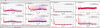
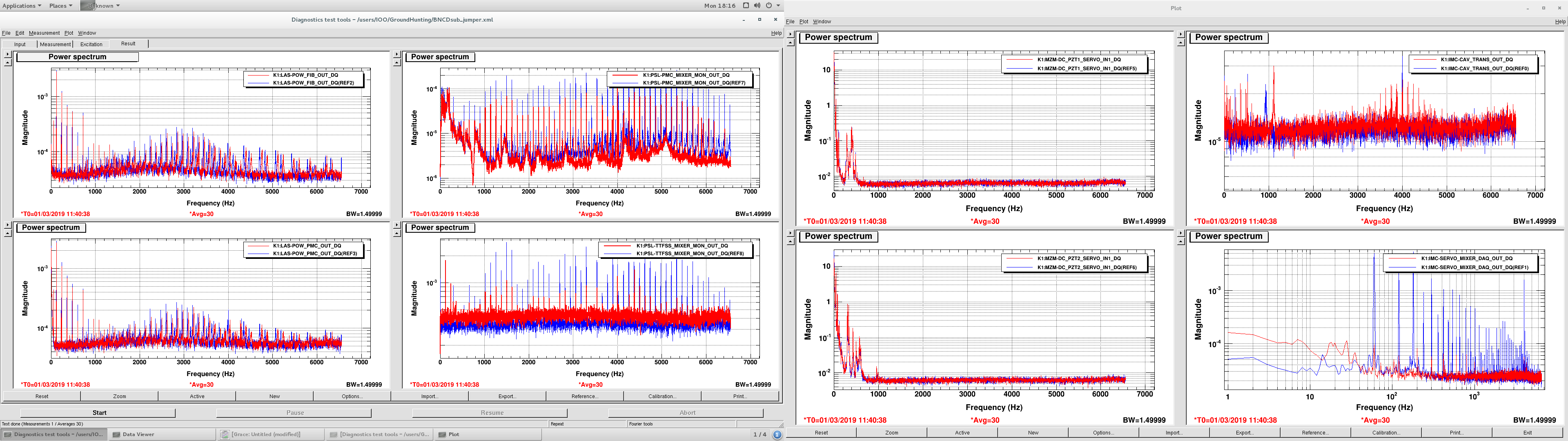
For the first step, I measured the spectra for (1) the laser power just after the fiber output, (2) the laser power after the PMC, (3) the error signal of the PMC loop, (4) the error signal for the RefCav loop, (5) the error signal for the 1st MZI PD1, (6) the error signal for the 1st MZI PD2, (7) the MCE TRANS PD signal (without the light), and (8) the error signal for the IMC loop. Figure 1 shows the spectra. The top left is (1), the bottom left is (2), the top mid-left is (3), the bottom mid-left is (4), the top mid-right is (5), the bottom mid-right is (6), the top right is (7), and the bottom right is (8).
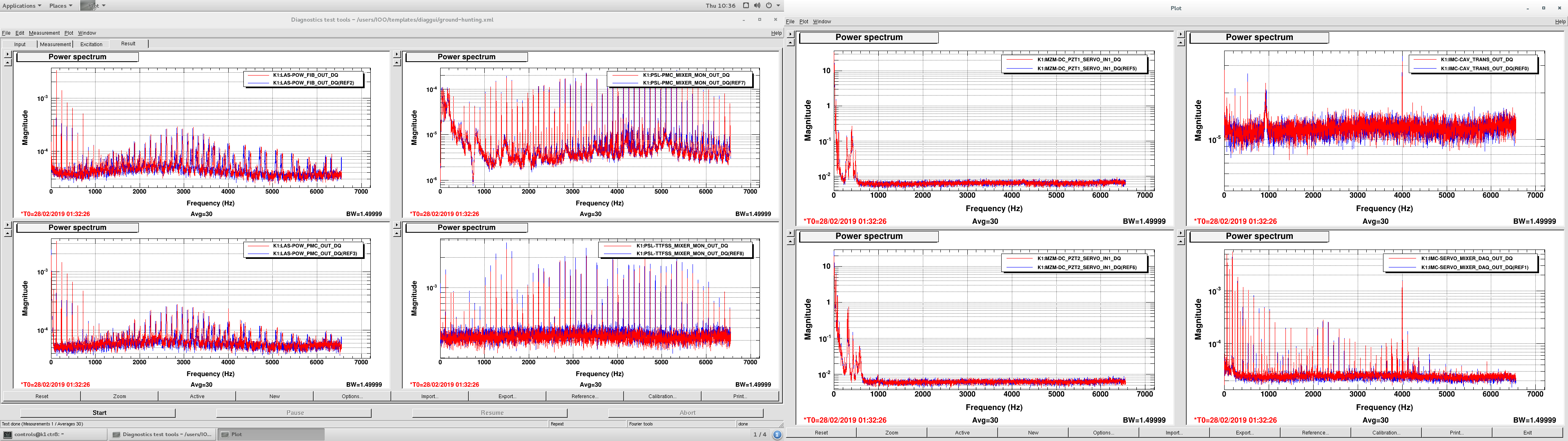
Fig.1 The spectra for the situation before we start the ground loop hunting. Blue and red shows same kind of the spectra.
2. Laser power inspection
As shown in (1), the laser light has huge 60-Hz harmonic peaks introduced in the fiber amp. Although I opened all of the loops in the PSL, still there was those. I also checked that it is not the noise introduced on the PD signal. If we turned the laser off, the PD signal has not harmonic peak, so we concluded that these peaks are included in the actual laser power.
3. Servo noise of the IMC
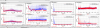
As shown in (8), the IMC servo has huge noise, even we have no signal on the PD. Here, the beam shutter in the PSL was closed and no light was on the PD. Then I found that the SERVO-IN2 port was connected to a one-side-disconnected cable. After I turned the IN2SW off, this peaks disappeared as shown in Fig.2.
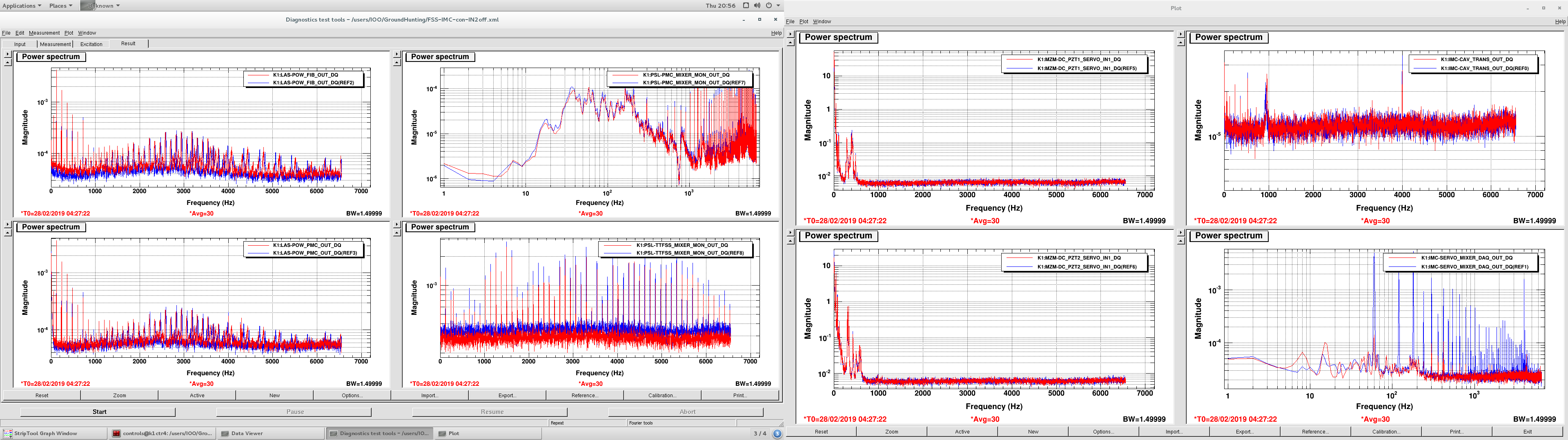
Fig2. Right bottom spectrum shows the peaks disappeared when IN2 was turned off (red) than it was turned on (blue).
4. Servo noise of the RefCav loop.
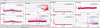
As shown in (4), the error signal of the RefCav loop has 60-Hz harmonic peaks up to more than 100th!! I expected that this comes from the IN2 input of the IMC servo, but the error signal of the RefCav loop still has the peaks after turning the IN2SW off as shown in the Fig.2. So, the reason for this noise is not such an annoying cable.
Then, I found that this noise disappeared if we disconnected the AOM and the IMC servo, as shown in the Fig.3. So I expected that we have the loop between the k1ioo rack. So I decided to have a careful look into the ground of each loop.
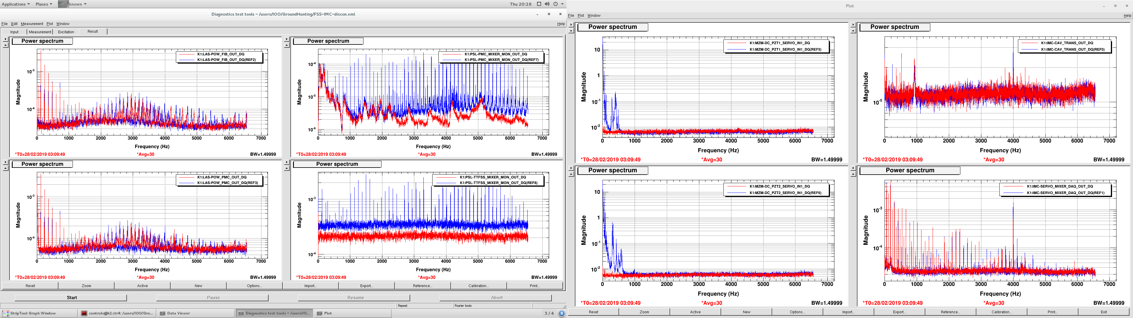
Fig.3. When we disconnected the AOM and the IMC servo, the bottom mid-right spectrum got quiet (red).
5. The ground check of the PMC loop and the FSS loop.
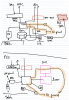
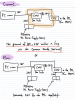
The ground was summarized in the Fig.4. I found two loops in total. One is the AC-ground -> the PZT driver for the PMC -> the PMC servo -> the function generator -> the AC ground, and the other is the AC-ground -> the laser controller -> the TTFSS servo -> the function generator -> the AC ground, We might change the plug of the oscillator from the 3-pin one to the 2-pin one, and see it helps.
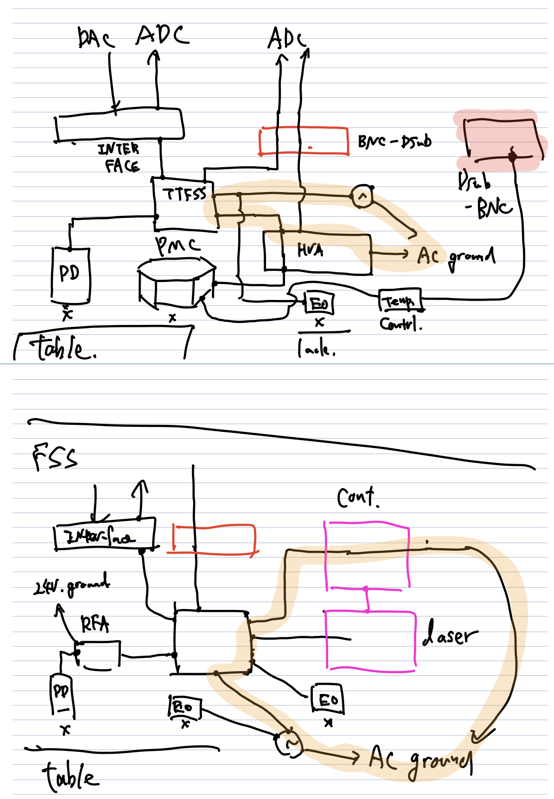
Fortunately, all of the optics such as the EOMs, the PDs, and the PZTs are not connected onto the PSL table, although the ground of the circuit is connected to the laser table. I suspect that the PZTsat the output of the PSL connect to the table, so I will see it tomorrow.
