Aso, Ohishi, Furuhata, Takahashi
(This is a report for the work done on 2016/2/24)
Summary
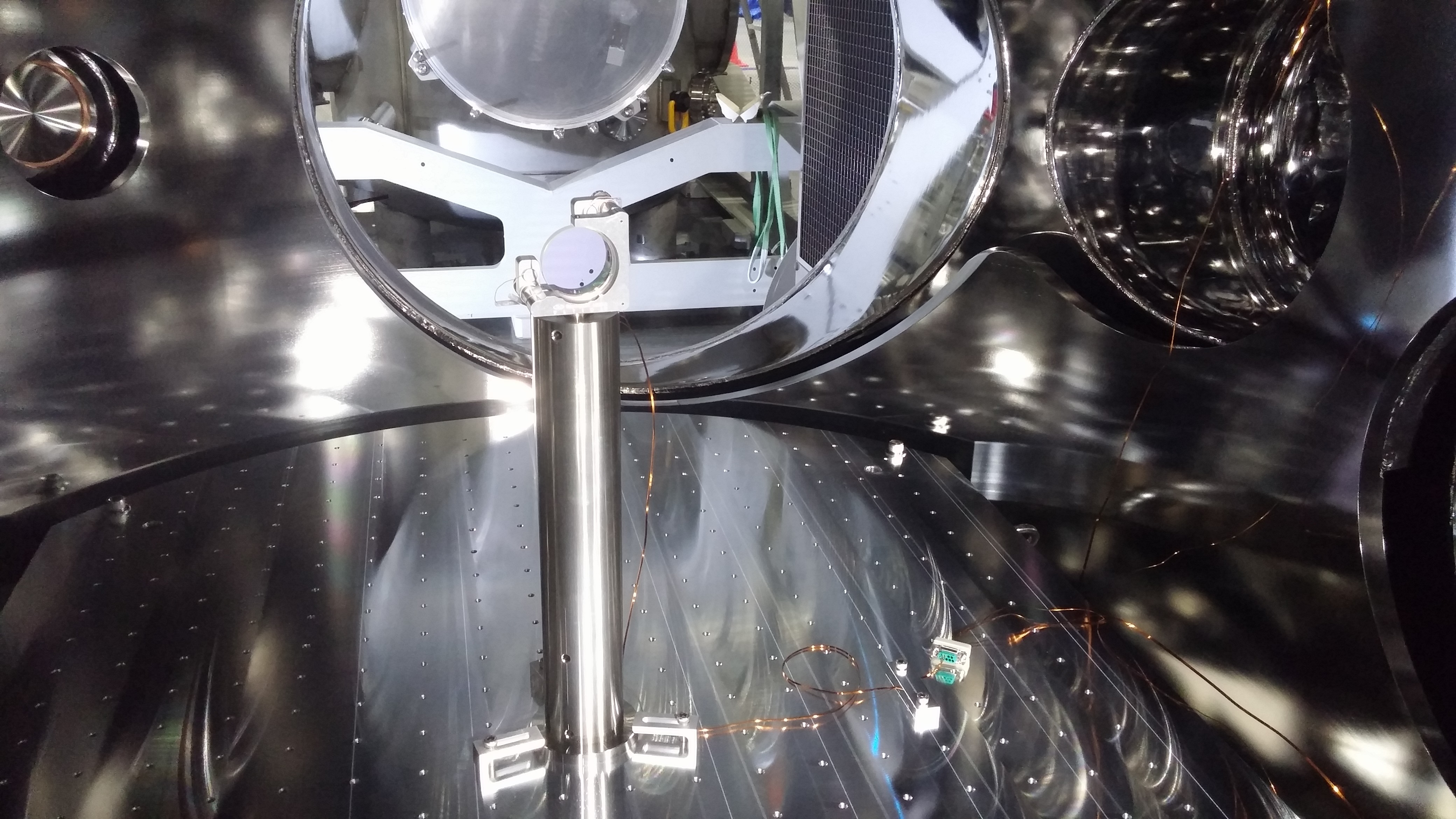
We have put the fixed PR2 mirror into the chamber. The mirror is sitting on the pillar roughly at the desired location (but not so precisely). The picomotor cabling is done. We did not perform the precise measurement of the bread board location with respect to the reference points on the floor.
Details
Bread board measurement
We intended to measure the position of the bread board with respect to the reference points on the floor first. However, the vacuum duct installed between the PR3 and PR2 now blocks us from accessing one of the reference points. Therefore we could not perform the measurement with the scheme we prepared. It will take time to develop and prepare aother measurement scheme. So we decided to skip the measurement assuming that the bread board is roughly centered in the chamber. The bread board should be centered with less than 1cm precision. Since the position of the PR2 needs to be adjusted to compensate for the error in ROC, which can be as much as 20cm, the position error of the bread board is not so relevant.
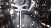
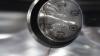
Assembly of PR2
PR2 mirror is 2inch diameter one made by SIGMA Koki. The ROC = 3000mm +/-200mm convex.
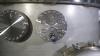
The mirror is mounted on a vacuum compatible version of Neport U200-A mirror mount with Picomotor actuators.
The cabling is done in the following way:
[Picomotor driver] -(RJ-22)--[conversion cable to D-SUB9]--[Flipper cable]--[Vacuum feed through flange]--(vacuum compatible D-SUB9)--[D-SUB9 to Burndy pin]--[Picomotor]
The flipper cable is used to cancel the pinout flip caused by the feed through flange.
The pinout is the following:
[Picomotor driver Ch1 (RJ22)] - [D-SUB9] - [Picomotor for Pitch]
3 (green) - 1 - Red
4 (Yellow) - 6 - White
[Picomotor driver Ch2 (RJ22)] - [D-SUB9] - [Picomotor for Yaw]
3 (green) - 2 - Red
4 (Yellow) - 7 - White
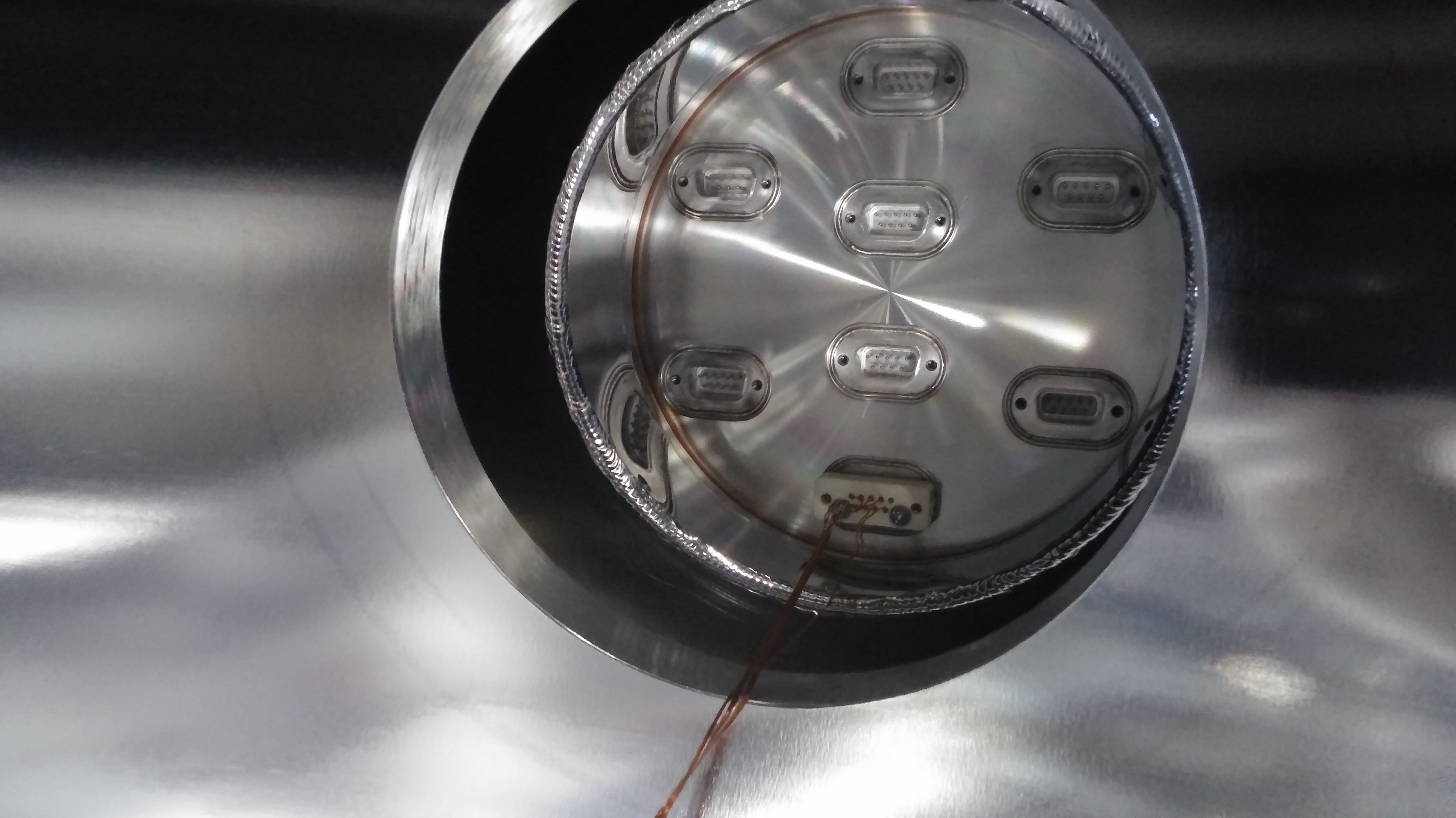
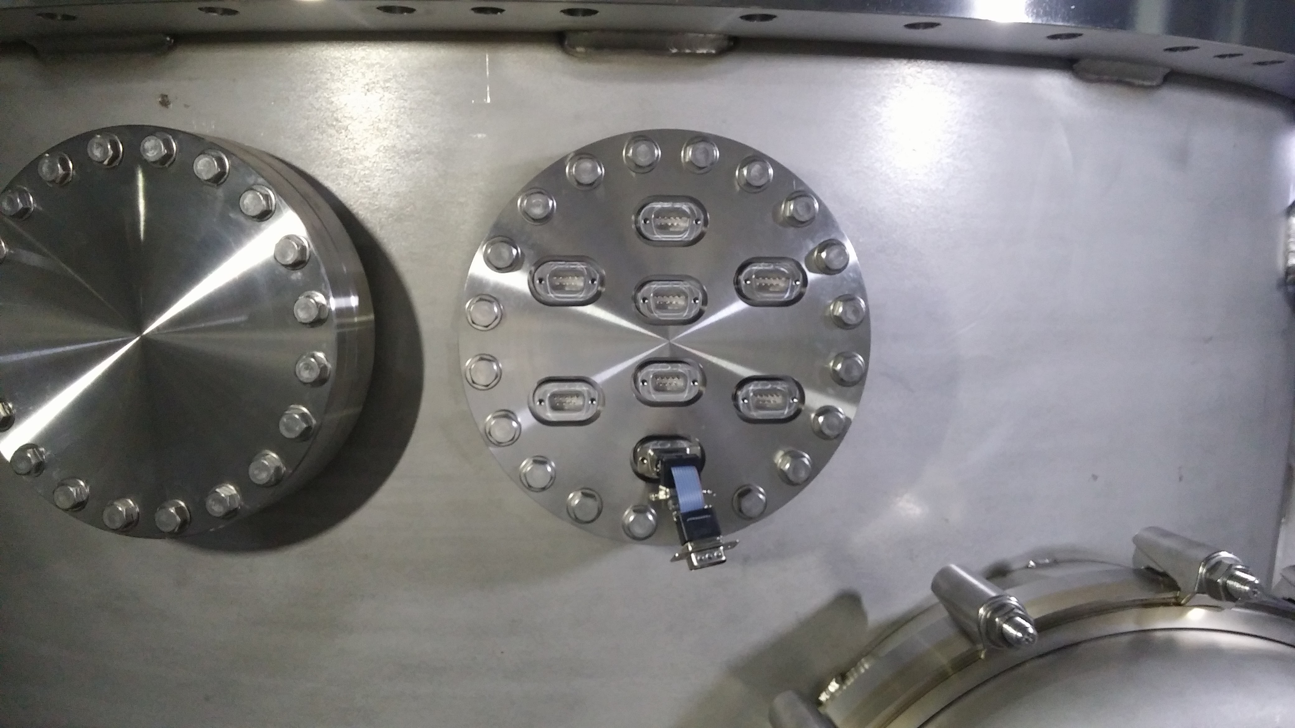
The feed through flange was attached to the F5 flange.
(See http://gwdoc.icrr.u-tokyo.ac.jp/cgi-bin/private/DocDB/ShowDocument?docid=4283 for naming convention)
We used the lower most D-SUB connector for the connection to the Picomotors.
The actuation check went well.
Current status
The vacuum chamber is closed. The feed through flange is tightened with 15N*m.
We wiped inside the chamber after the work, but more thorough wiping will be necessary after the position adjustment of PR2 is done.
Remaining tasks
We need to bring the TCP/IP network to the picomotor driver so that we can control it remotely. We are planning to do it on 2/25.