Reports 1-1 of 1 Clear search Modify search
MIF (General)
masayuki.nakano - 13:34 Sunday 03 February 2019 (7943) Print this report
SR2 alignment for the SRM

[Yokozawa, Wang, Nakano]

Today, we aligned the SR2 to bring the beam to the center of the SRM again, because the SR3 alignment was changed to bring the GR to the Yend. We moved the SR2 by +2.5 mrad in pitch and ~+0.5 mrad in yaw by the pico-motor.

The SR2 was aligned well and the oplev was centered. One concern up to here is the beam position on the SR2. The SR3 angle was fixed by the GR and if the GR hit the center of the SR2, IR should also hit the center of the SR2. However, the IR beam hits the position of 1cm in +X direction. At some point, we need to check the IR and the GR is overlapped.

And another problem is the beam position on the VP of the GV between the SRM and the OMM chamber. The beam is clipped on the VP, that means the beam is off-centered by ~4 cm in -X direction. We discuss and concluded the wedge direction is opposite. The detail is as follows:

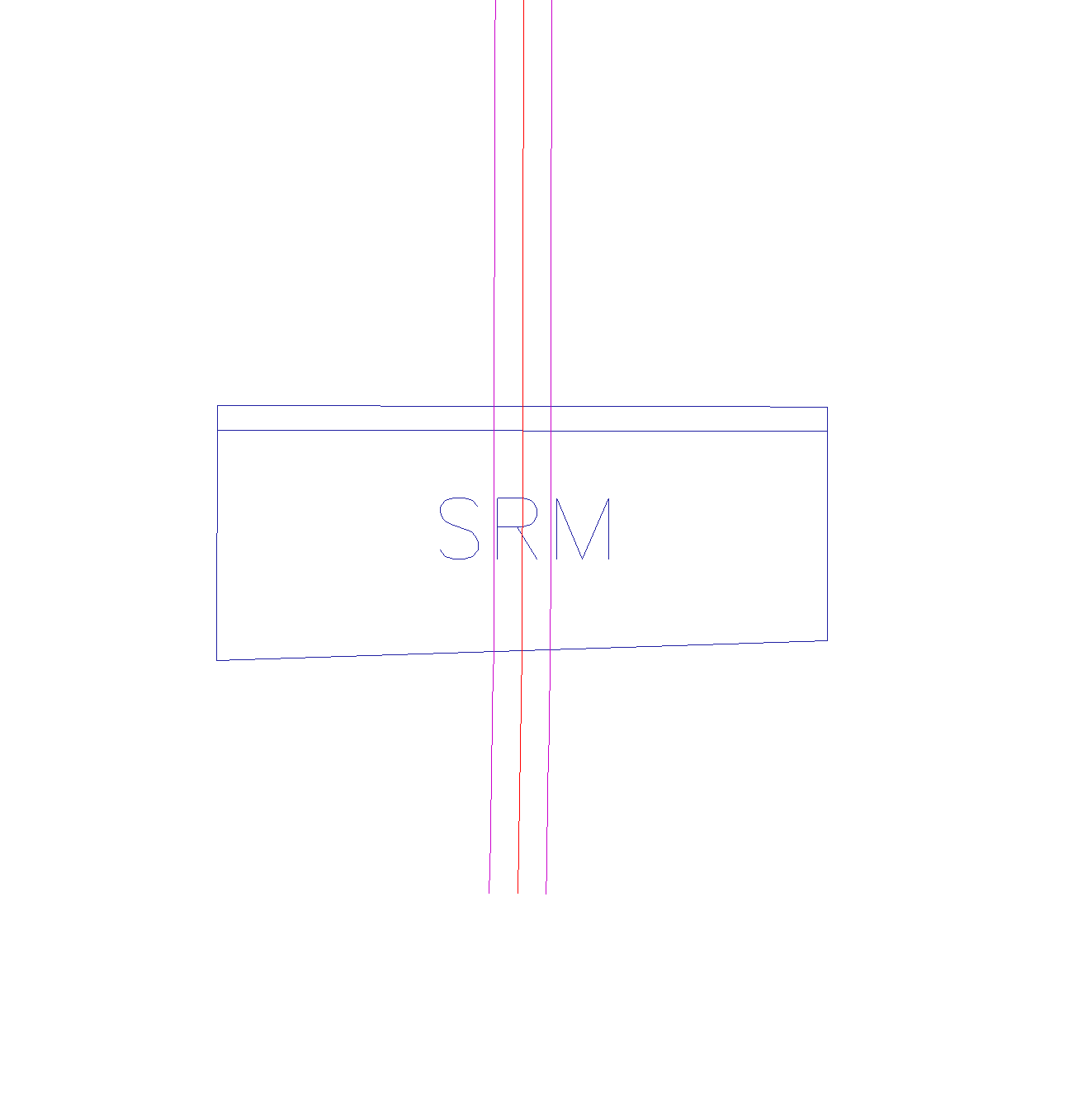
* The current situation seems consistent with the chamber CAD drawing JGW-D1707268. The attached sketch shows the current predicted status of the SRM.
* However this is inconsistent with the PRM asymmetric direction.
* Also, the optical design (shown on the first page in JGW-G1809367 for example) shows the beam to the OMMT1 goes from -X to +X direction, and it is inconsistent with the current situation.
* So we concluded that the SRM was installed in the opposite way, and this fault did not happen in the installation but in the design.

Fortunately, the current SRM is 2inch one and easy to rotate by 180 degrees. So we are going to flip it early in the next week.

Non-image files attached to this report
Comments to this report:
yoichi.aso - 16:01 Sunday 03 February 2019 (7945) Print this report

Actually, the current wedge direction of SRM is correct with respect to the original design of the main interferometer optical layout.

The master layout of the main interferometer is defined in this document:

https://gwdoc.icrr.u-tokyo.ac.jp/cgi-bin/private/DocDB/ShowDocument?docid=2379

You can open bKAGRA.dxf to see it. For your convenience, I attached a zoomed rendering of the DXF file around SRM.

Since all the KAGRA optical layout is based on this JGWDoc, if the OMC design assumes the opposite wedge direction, it is a mistake in that design, not in the SRM wedge direction.

Anyway, how to handle this problem should be discussed carefully with people from Type-B, OMC, MIF and VAC.

Especially, I'm curious how the position of the GV window between the SRM and OMMT was decided.

Images attached to this comment
eiichi.hirose - 18:47 Sunday 03 February 2019 (7946) Print this report
If the issue is fixed by 180 degree rotation of the mirror, the original one-piece SRM (250mm-diameter) will be fine as well. If my memory is correct, VIS team has not yet glued wire breakers etc into the optic with EP-30. Even if they did it already, we should be able to remove them without damaging the mirror and glue them again.
mark.barton - 8:12 Monday 04 February 2019 (7948) Print this report

Type B worked from a sketch by Aso-san which conforms to JGW-D1402379 and has the thick part of the wedge on the left as viewed from the back, which agrees with what Yokozawa-san-tachi found.

Hirata-san says it's about an hour's work to change it by 180° if that's what people want to do. We would lock the IP, immobilize the metal optic, flip the glass optic assembly and then release everything.

We have not put prisms on the large glass SRM but it wouldn't have mattered because we put them exactly on the vertical centerline, so it's naturally reversible.

Search Help
×

Warning

×