Simon, Yano, Akutsu on 16 Jan 2019
Brought the 4th WAB into the EXC chamber, and checked the alignment of the suspended WAB in the suspension.
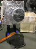
Unpacking the WAB
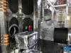
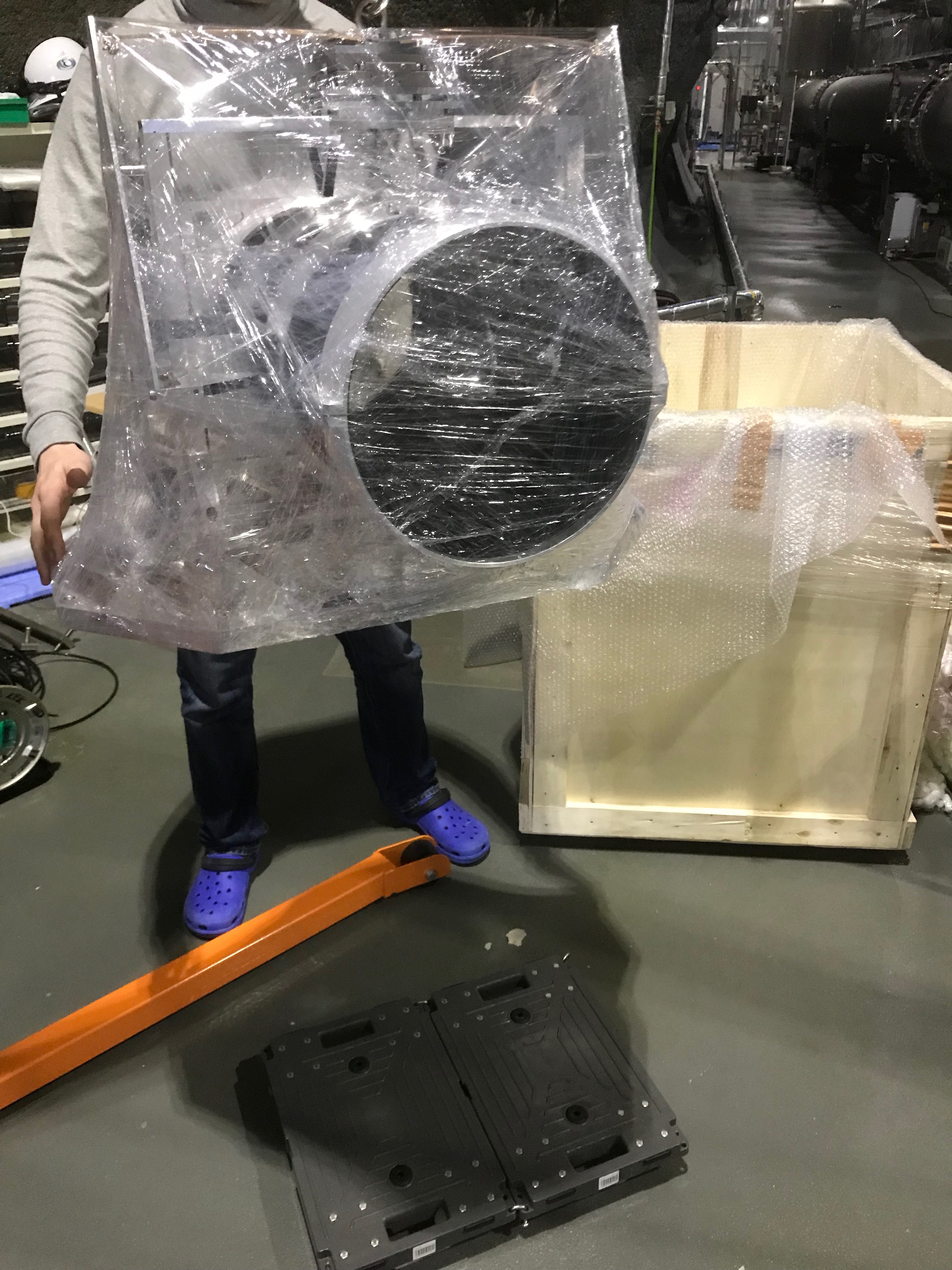
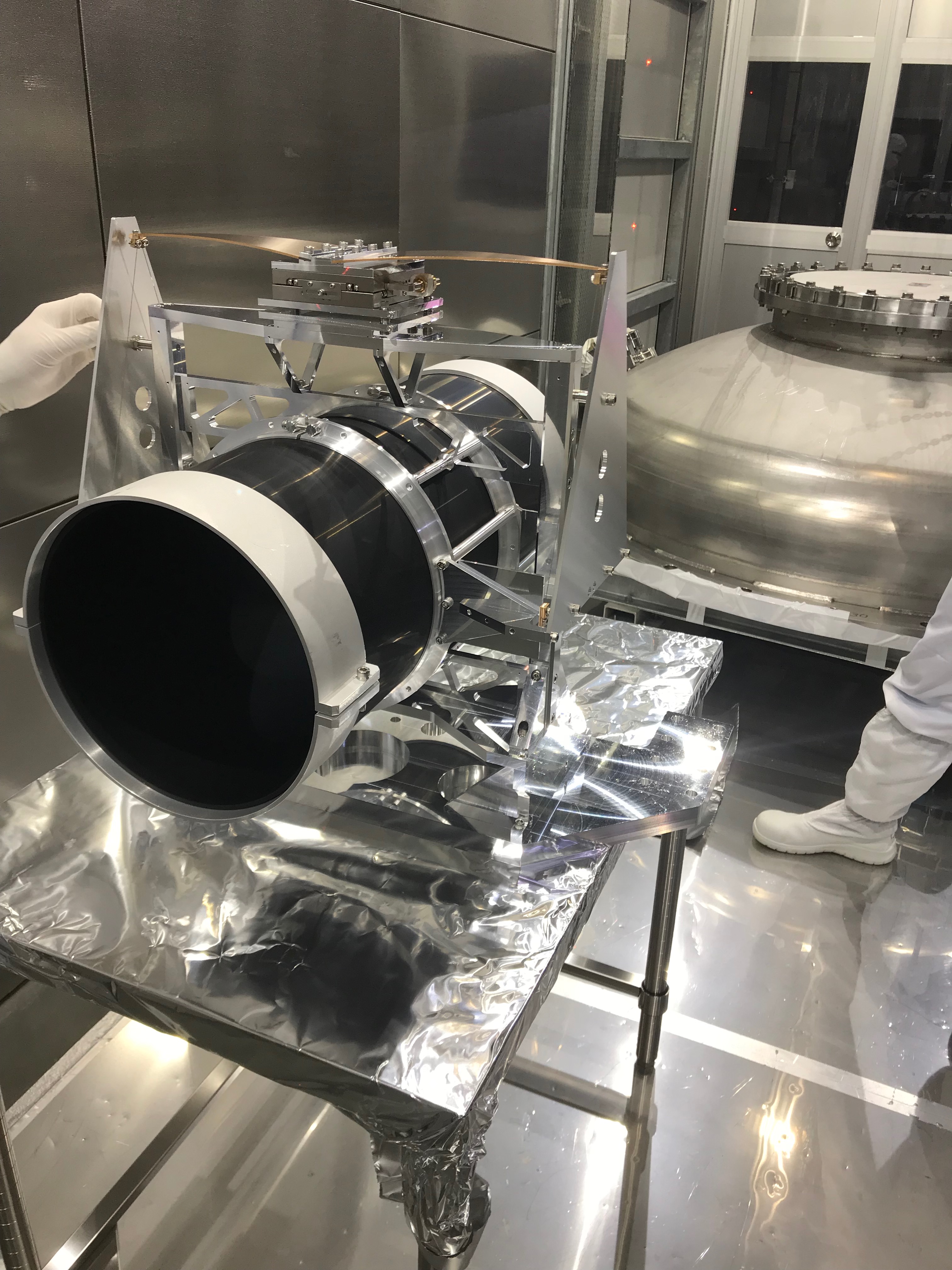
Firstly we took out the WAB from the wooden box with an engine crane brought from NAOJ (Fig 1). Using low-floor carry carts, putting the WAB on it, we succeeded to make it pass under the arm duct in the X room to reach the "opposite" side of the cryostat against the cryopayload shop. After bringing the WAB into the clean booth (Fig 2), we checked around it and found nothing bad.
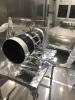
Removing an extended cooling bar
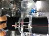
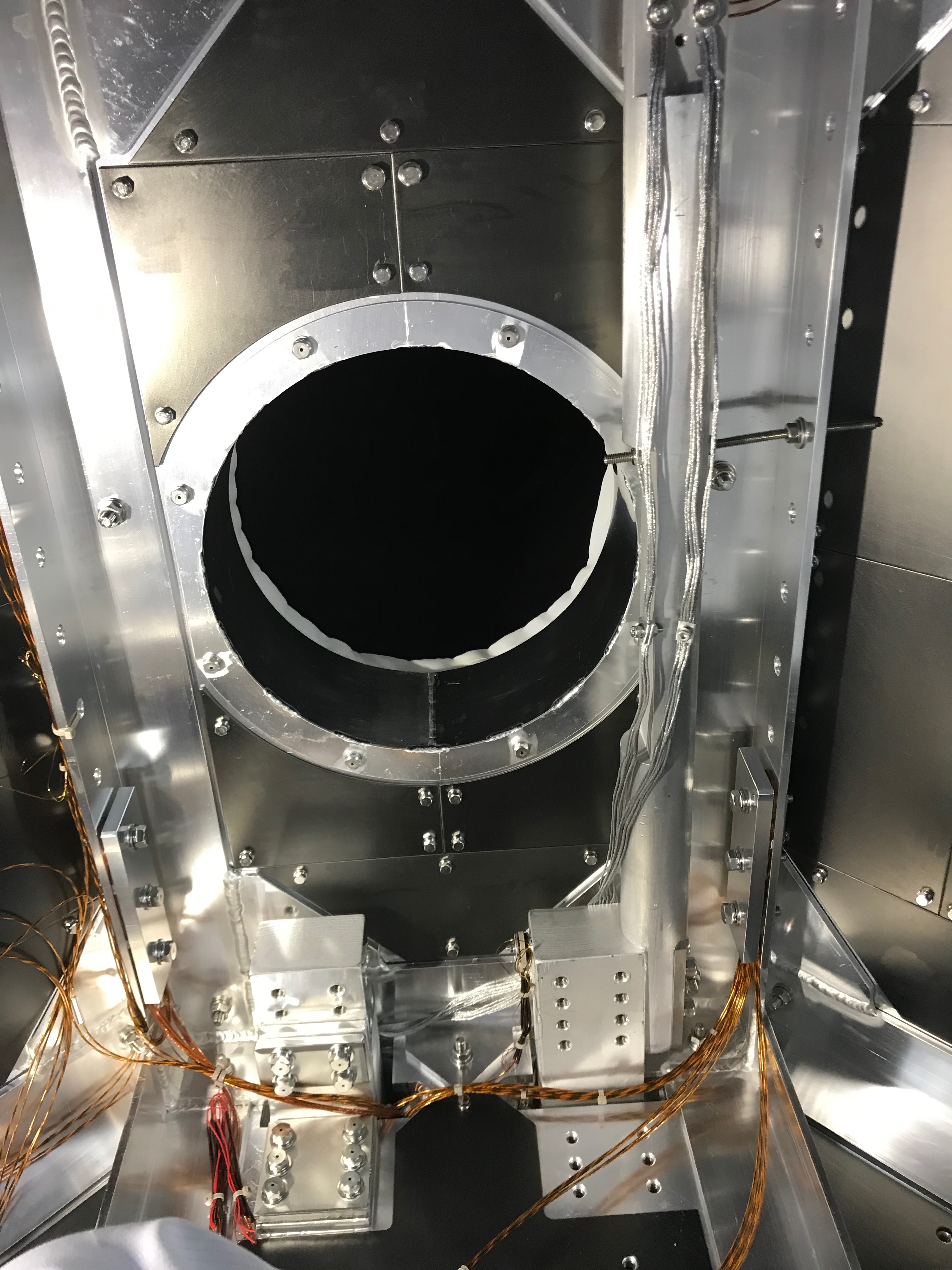
We found that an extended cooling bar attached onto the cooler head has something sticking out or bending into the line of the duct to the level that the WAB would be mechanically interefere against it when the WAB will be in the saving mode (Fig 3). So we discussed with Tomaru-san there and detached the extended cooling bar.
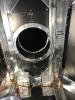
Installing the WAB
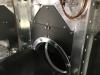
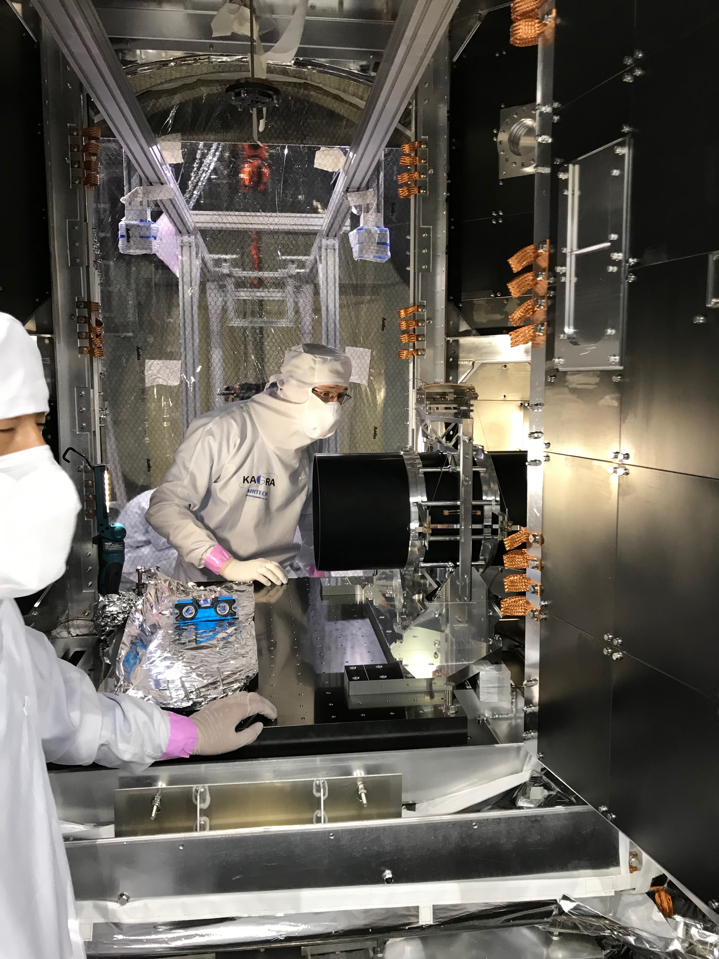
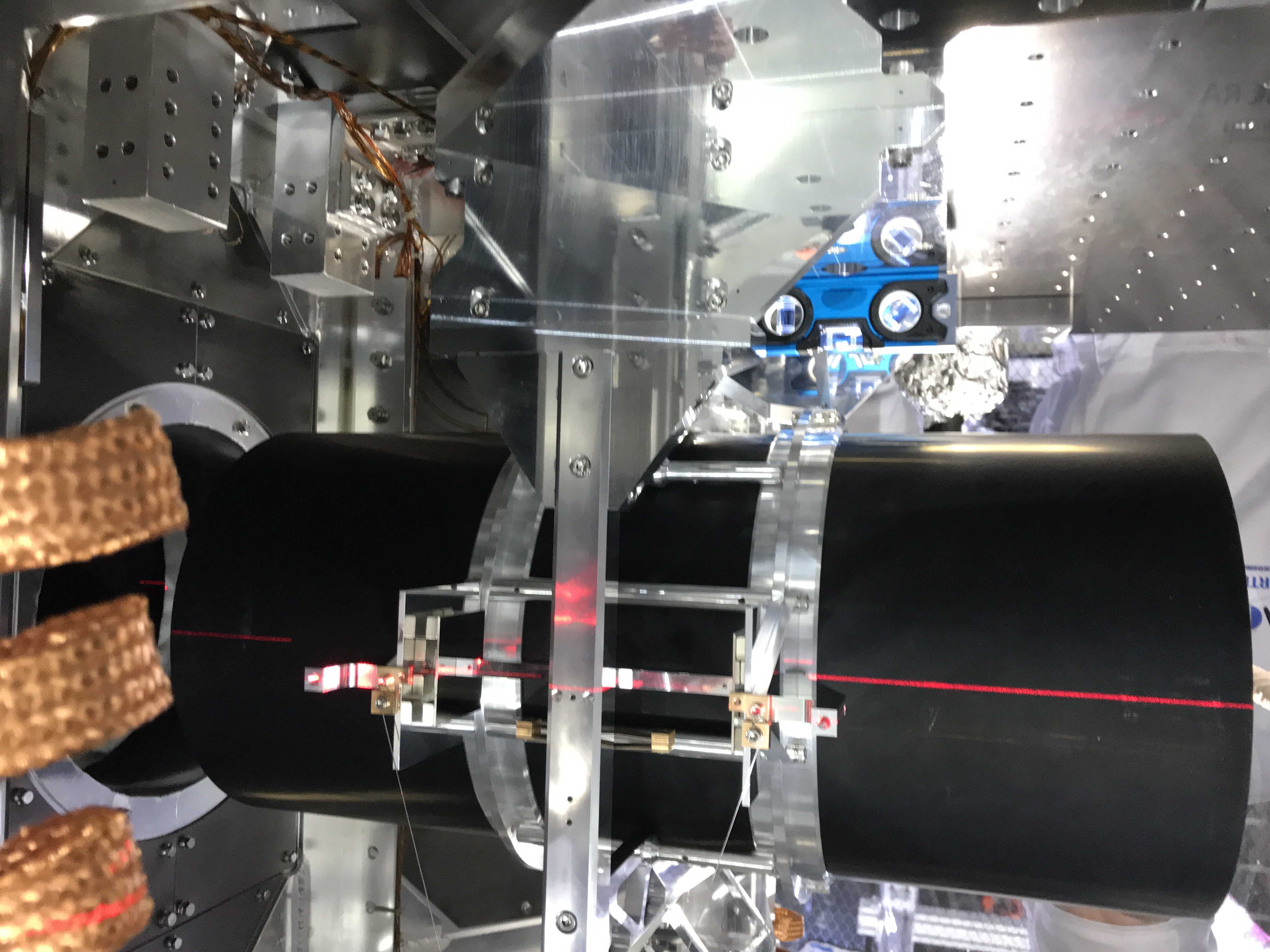
We ummerged the upper part of the WAB suspension and the lower part, and firstly brought the lower part into the cryostat and put it on the breadboard there (Fig 5). After fixing it with slim cap M6 screws, we brought the upper part on it and also fixed. Then detached the protectors for the both edges, and then detached the suspension protectors to do sanity check. In addtion, we attached the magnet dampers to the WAB suspension (Fig 4).
Sanity check
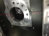
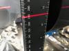
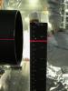
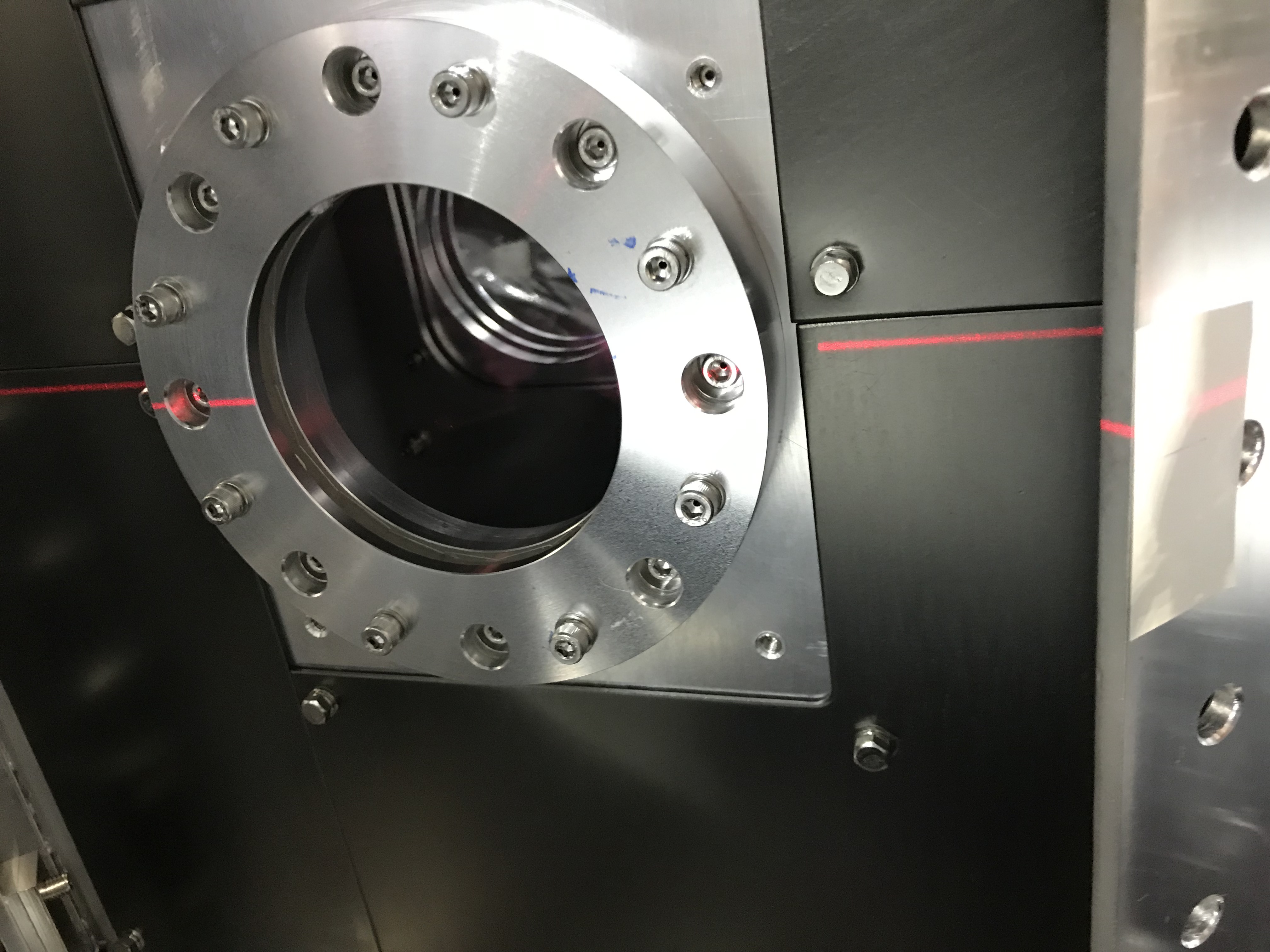
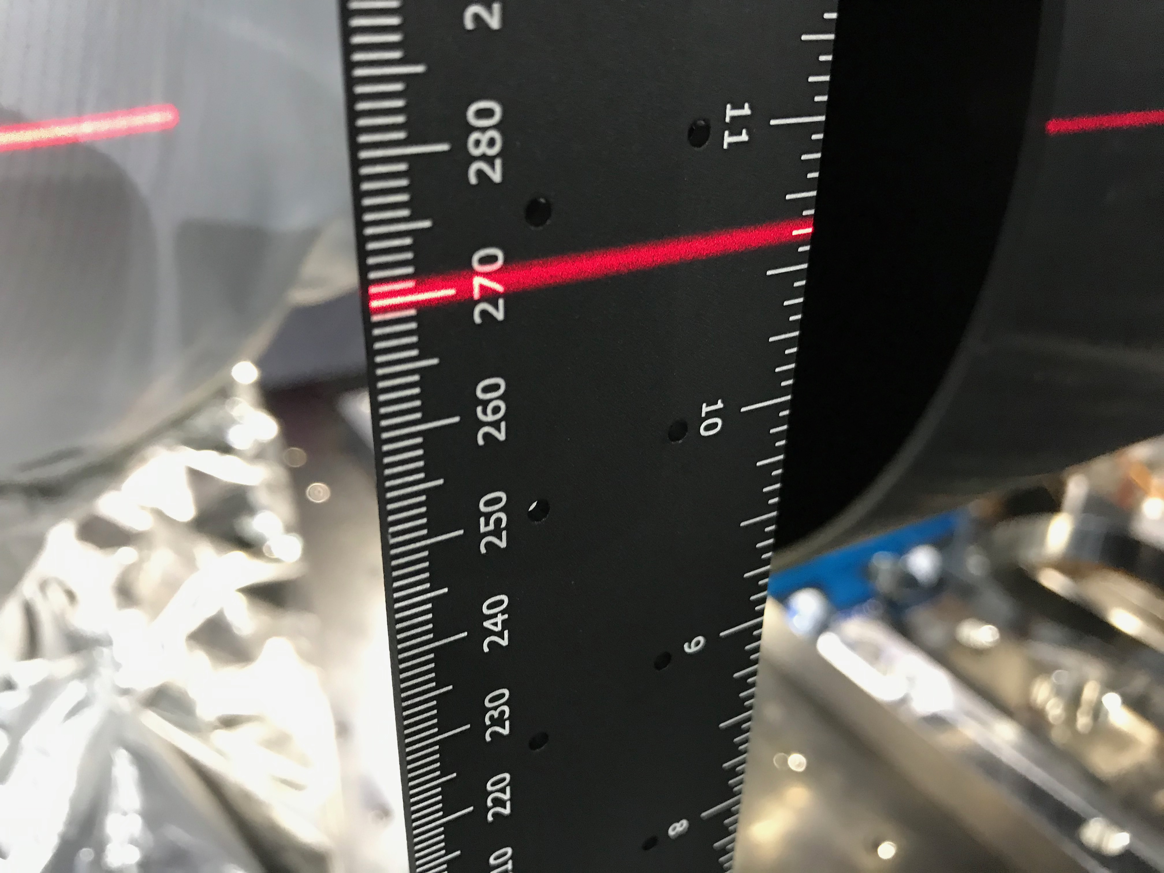
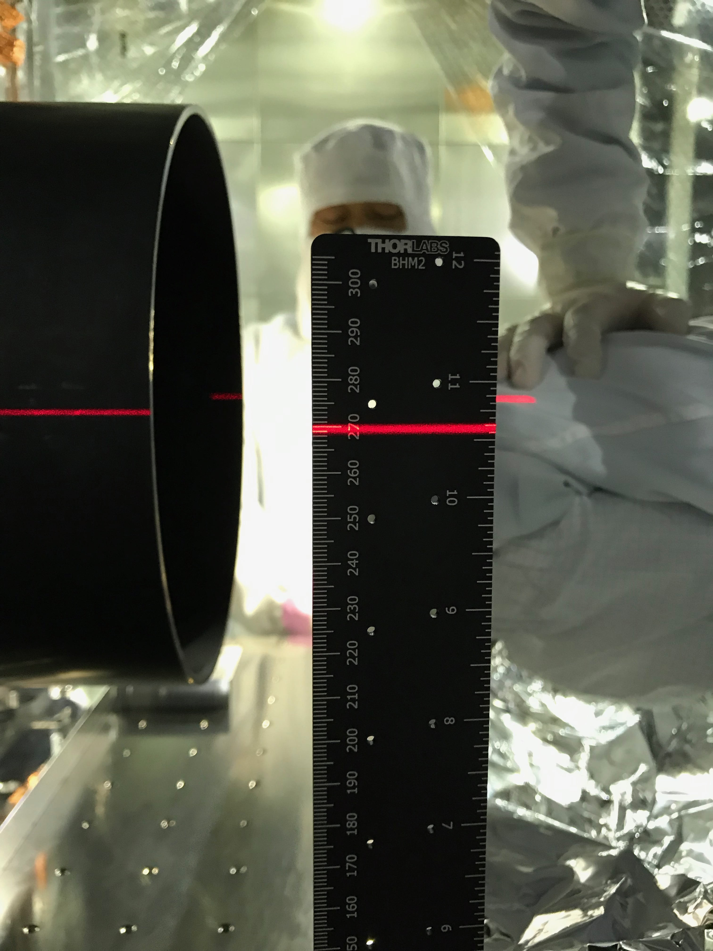
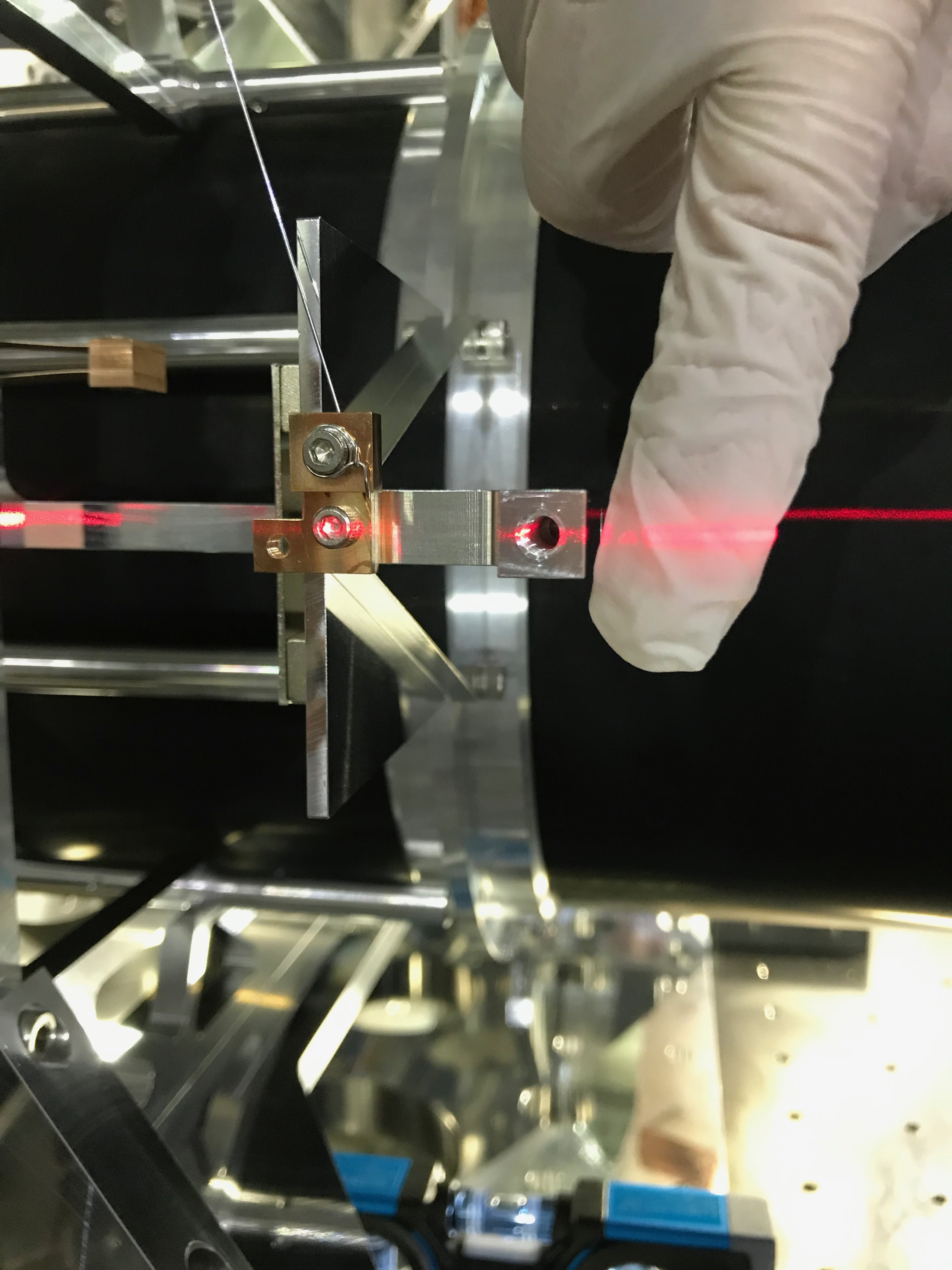
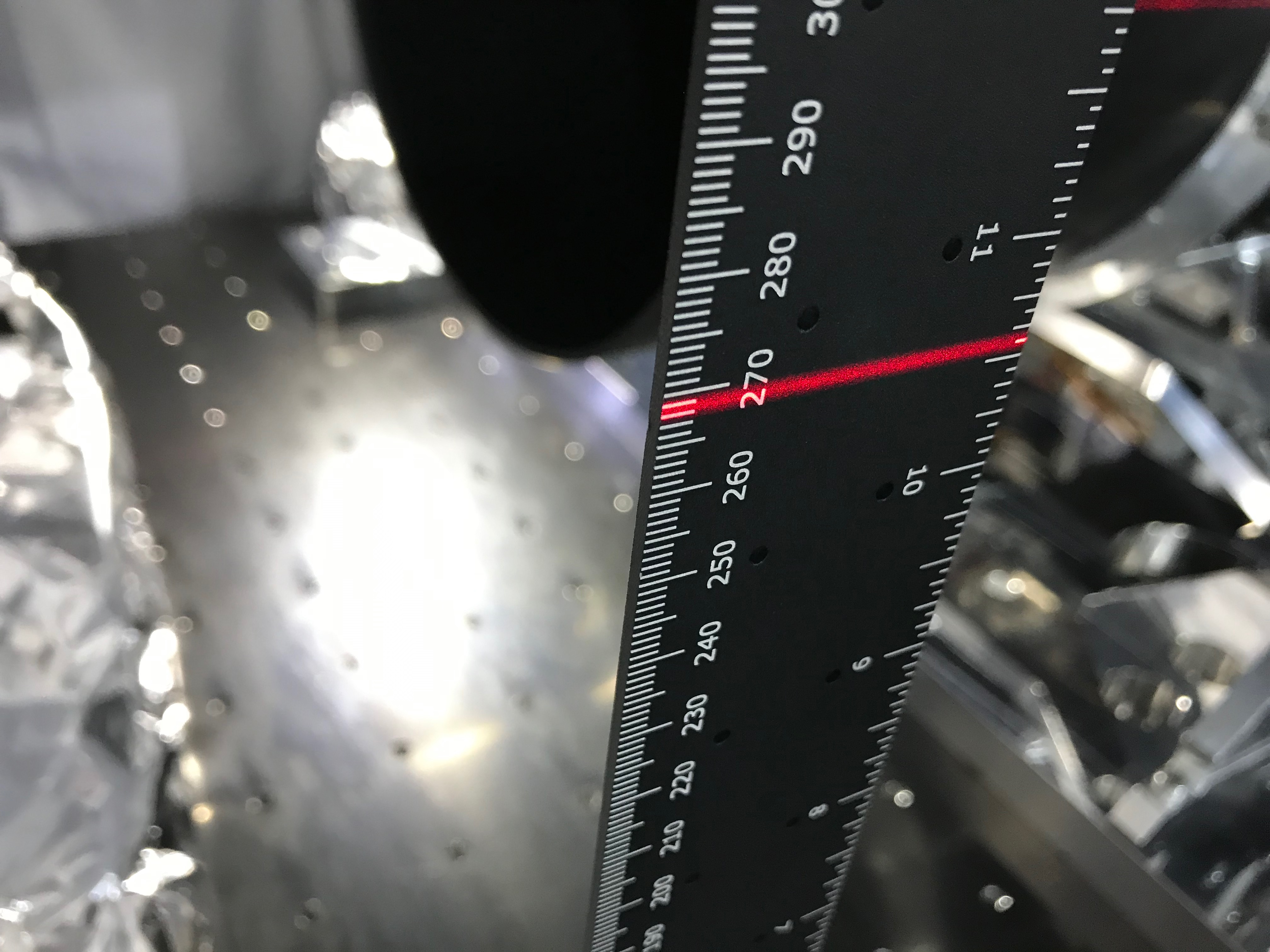
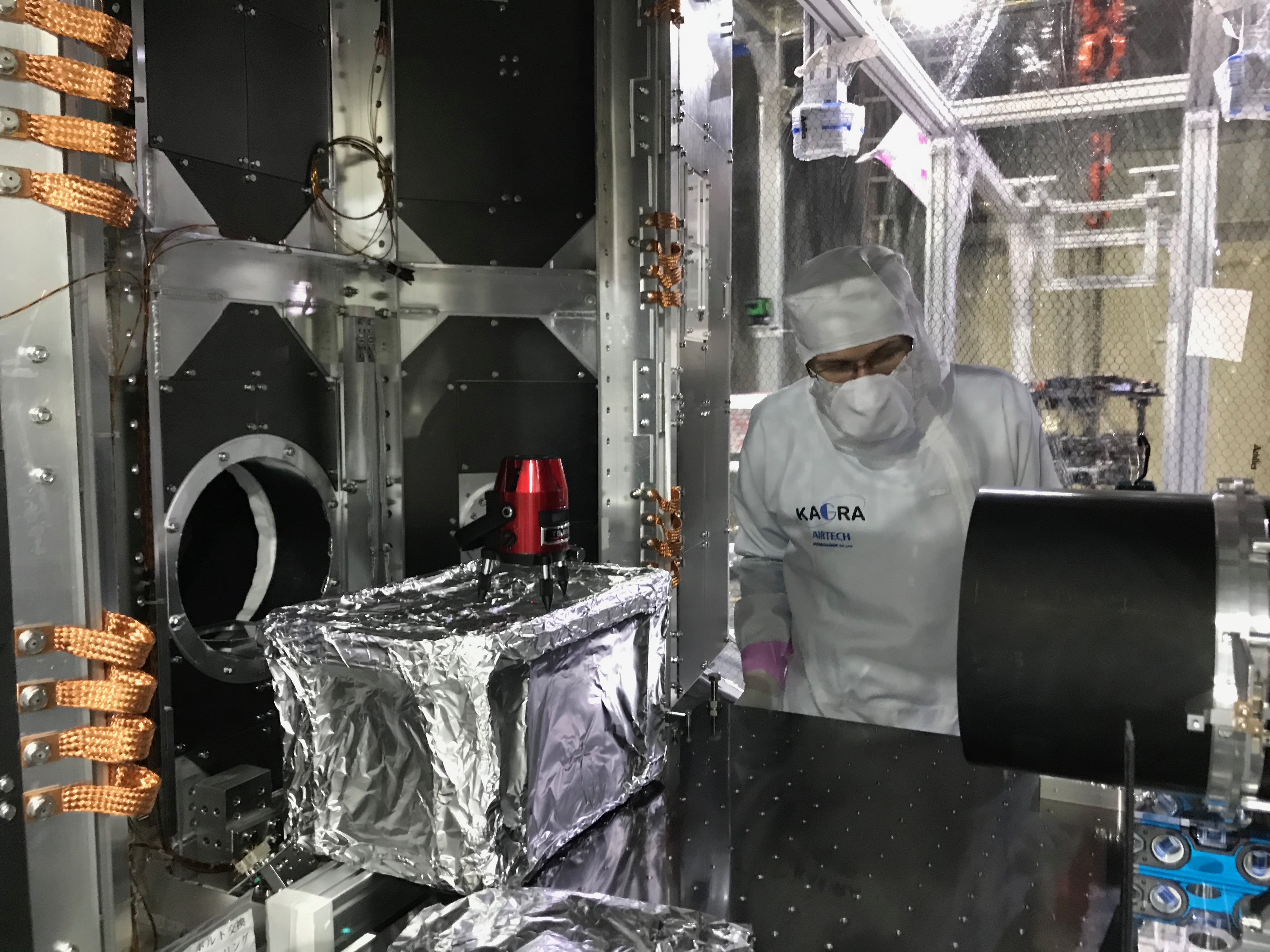
With a laser level, we illuminated the virtual line of height of the center of the ducts attached to the inner sheild (Fig 6); actually there were no such indications attached in the inner shield, so we shot the center of the screw heads for the viewports at the center line (probably... the error would be +/- 1mm). The height was about 270.5mm (Fig 7). Then we illuminated the center of the freely suspended WAB from each of the both sides, and comfirmed they are around 269.5-268.5 mm both (Fig 8, 9 from -Y side, Fig 10, 11 from +Y side). So we comfirmed that the vertical postion in room temperature, the roll, and the pitch.
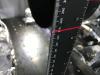
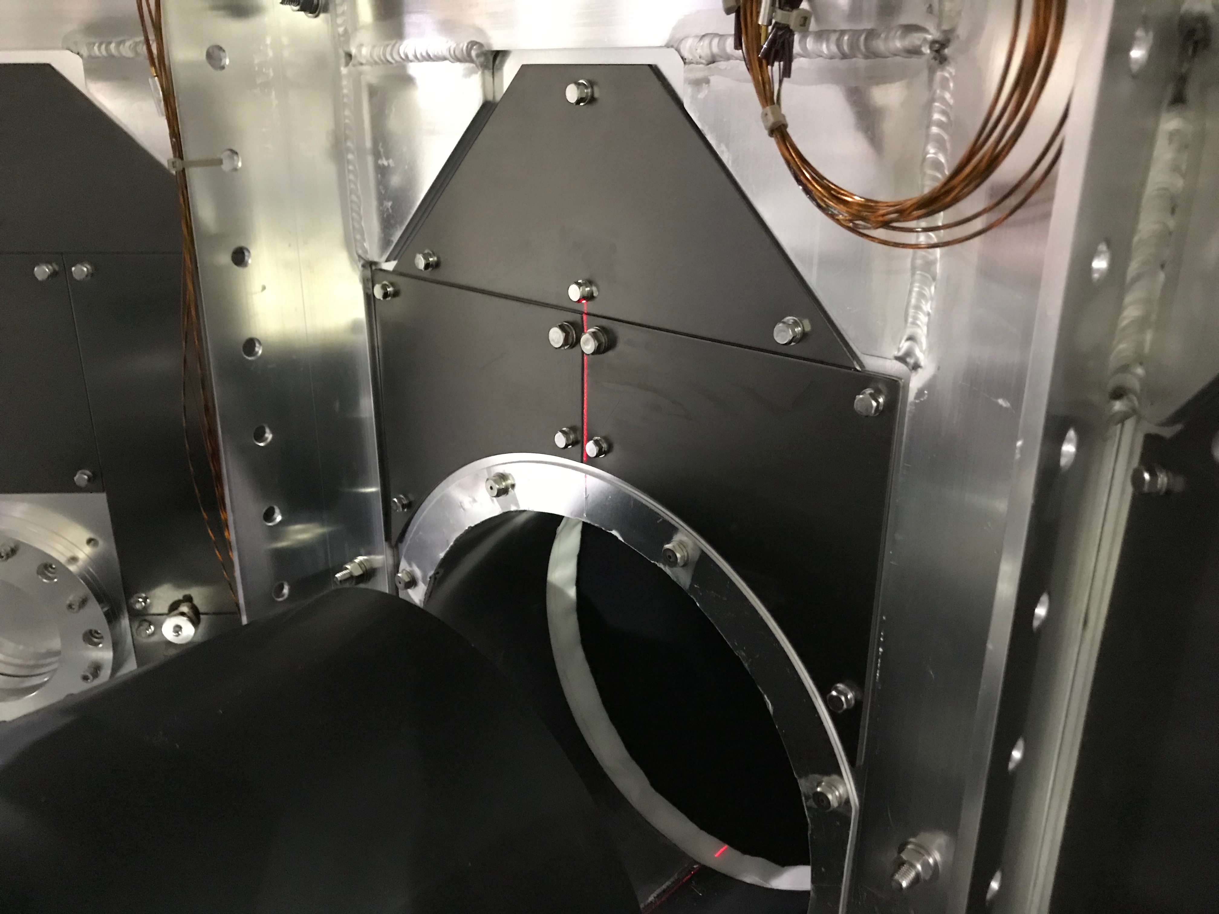
Then we put the laser level on a box to illuminate the WAB from its front to check the horizontal position and the yaw. Again it was hard to align the beam along the scratch line on the breadboard (Fig 12, 13), we somehow do it, and comfirmed those DoFs were ok.

