With Enzo and Hirata-san.
Today:
-
We debugged the F0 FR stepper issue:
- We checked the stepper coil resistances just before the driver, and they were both 6.4 Ω, which is about right, so there were no cables broken.
- The cable length external to the tank was 5 m, the same as for several working steppers.
- The driver was S1706032 for GAS (including F0) and S1706044 for IP, both built by AEL (not Tanaka-san of NAOJ).
- After some swaps, we discovered that we had a single half-dead output, #2, on the BS_GAS driver, and all other channels on both drivers worked. Therefore we moved the F0 FR cable to output #3.
- We revisited the vertical centering of the FR. With the carriage upside down from originally, the new usable range is 45 mm (bottom) to 100 mm top, with a mid-range of 78 mm. We set the stepper driver to 0 counts and then manually adjusted the FR to mid-range.
- We explored the usable range with the stepper. The total range is about ±1,500,000 counts, but we recommend limiting it to ±1,400,000 counts, which gives a margin of about 2 mm at each end.
-
We tried zeroing the BF and SF with the respective FRs.
- The BF started at 770 µm (with no LVDT offset and 0 counts on the stepper driver) and could be easily zeroed against the LVDT with 300,000 cts of FR. (Note positive FR counts move the keystone down.)
- The SF started at 571 µm with 450,000 counts on the stepper, and stopped at 495 µm somewhere just before 650,000 counts. We tried 850,000 counts and there ws no more movement. We returned to 450,000 counts and the SF went to 722 µm. So we must have run into the lower stop and missed a few counts, but there was no jamming, and the carriage reversed easily.
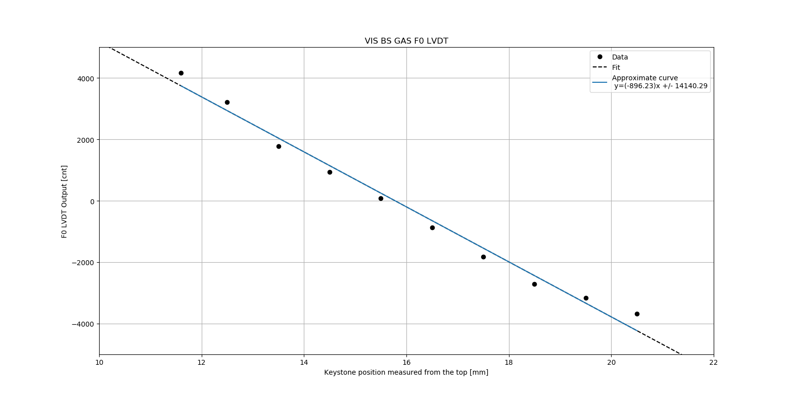
- We took data for recalibrating the F0 LVDT, for values of height from 11.6 mm to 20.5 mm, measured down. (These limits were chosen as the point where some additional resistance was felt.) See forthcoming klong by Enzo.
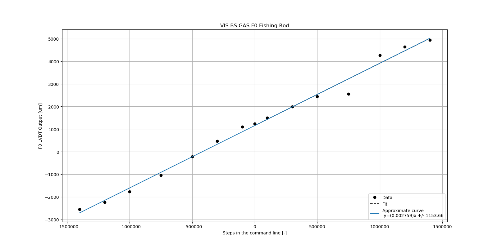
- We also took data for the response of the keystone to different heights of the FR. See forthcoming klog by Enzo.
- We tried unlocking the IP but it had a fair bit of yaw which we had no time to fix, so we left it locked and replaced the tank lid.