Simon, Yano, Akutsu on 8th Jan 2019
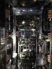
Began the finalization of the WAB in the IYC chamber.
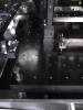
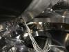
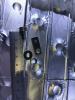
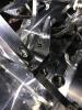
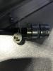
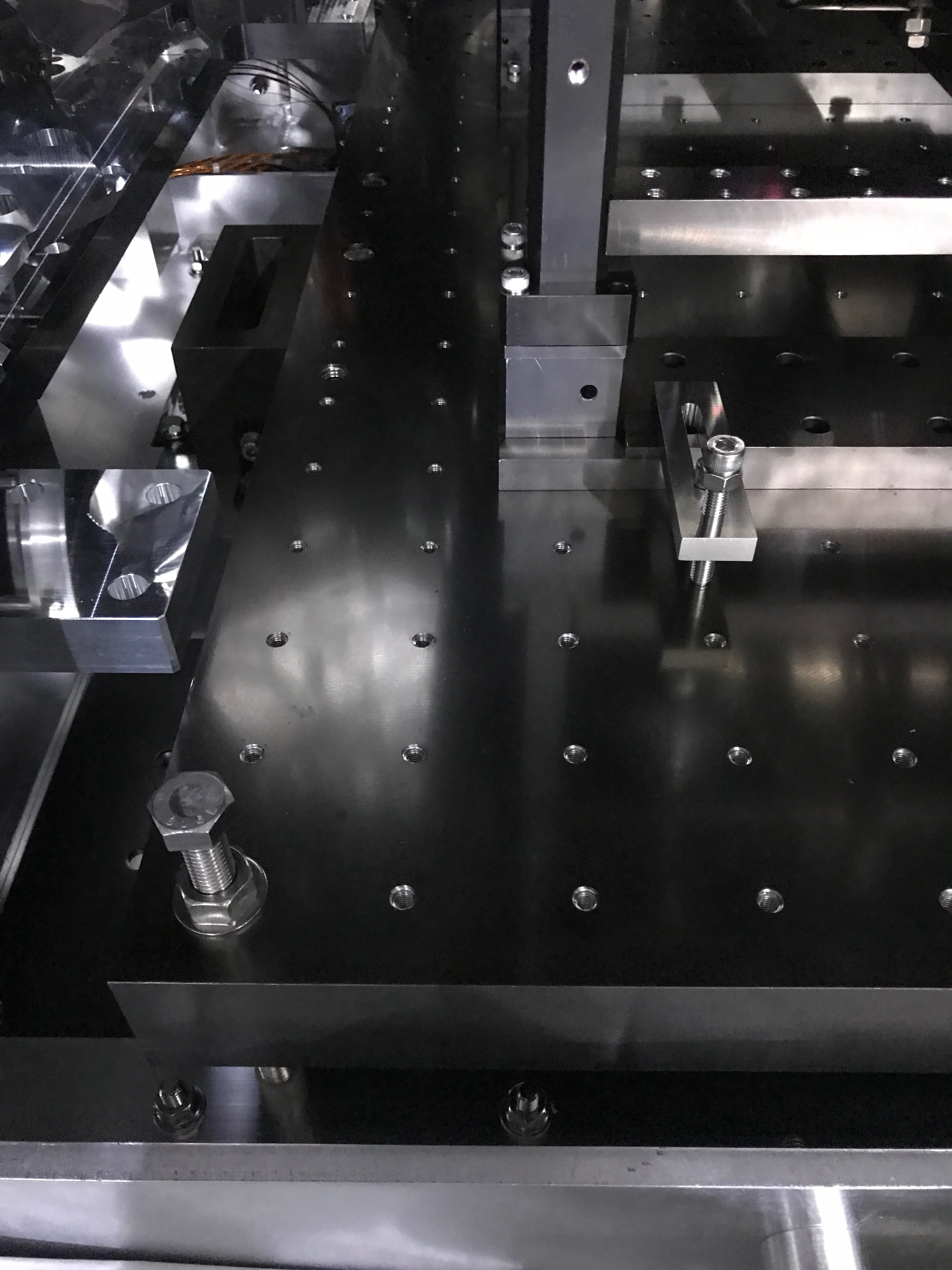
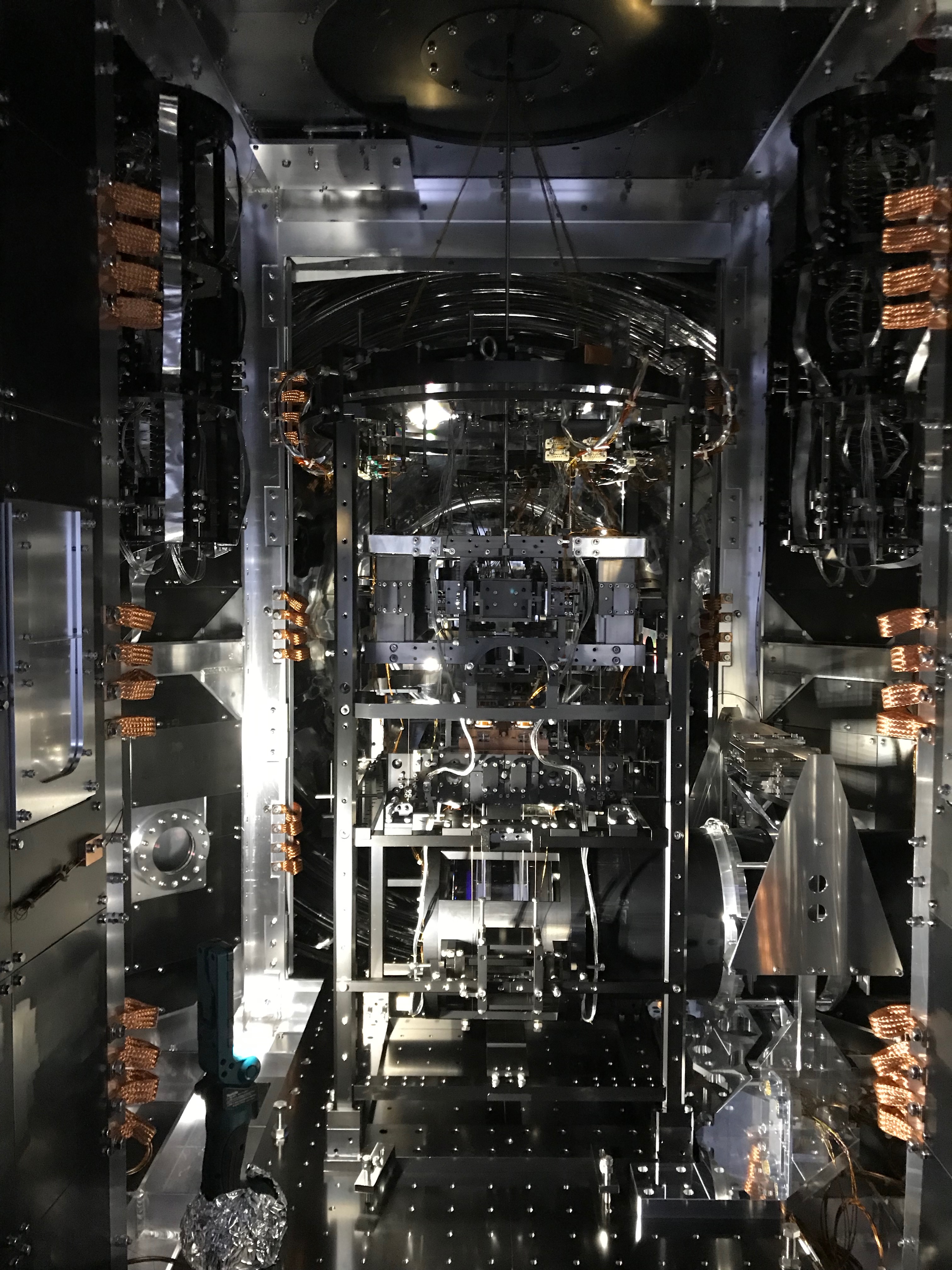
- First of all, we found two of the clamps fixing the security frame for the cryopayload would be going to mechanically interfere against the base plate of the WAB suspension when it would come back to the nominal position (Fig 1). After informing that to cryo, we shifted each of the two by one line of screw holes on the breadboard to widen the space.
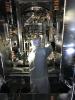
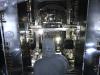
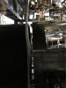
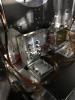
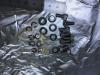
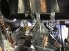
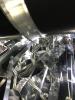
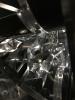
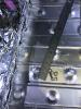
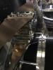
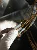
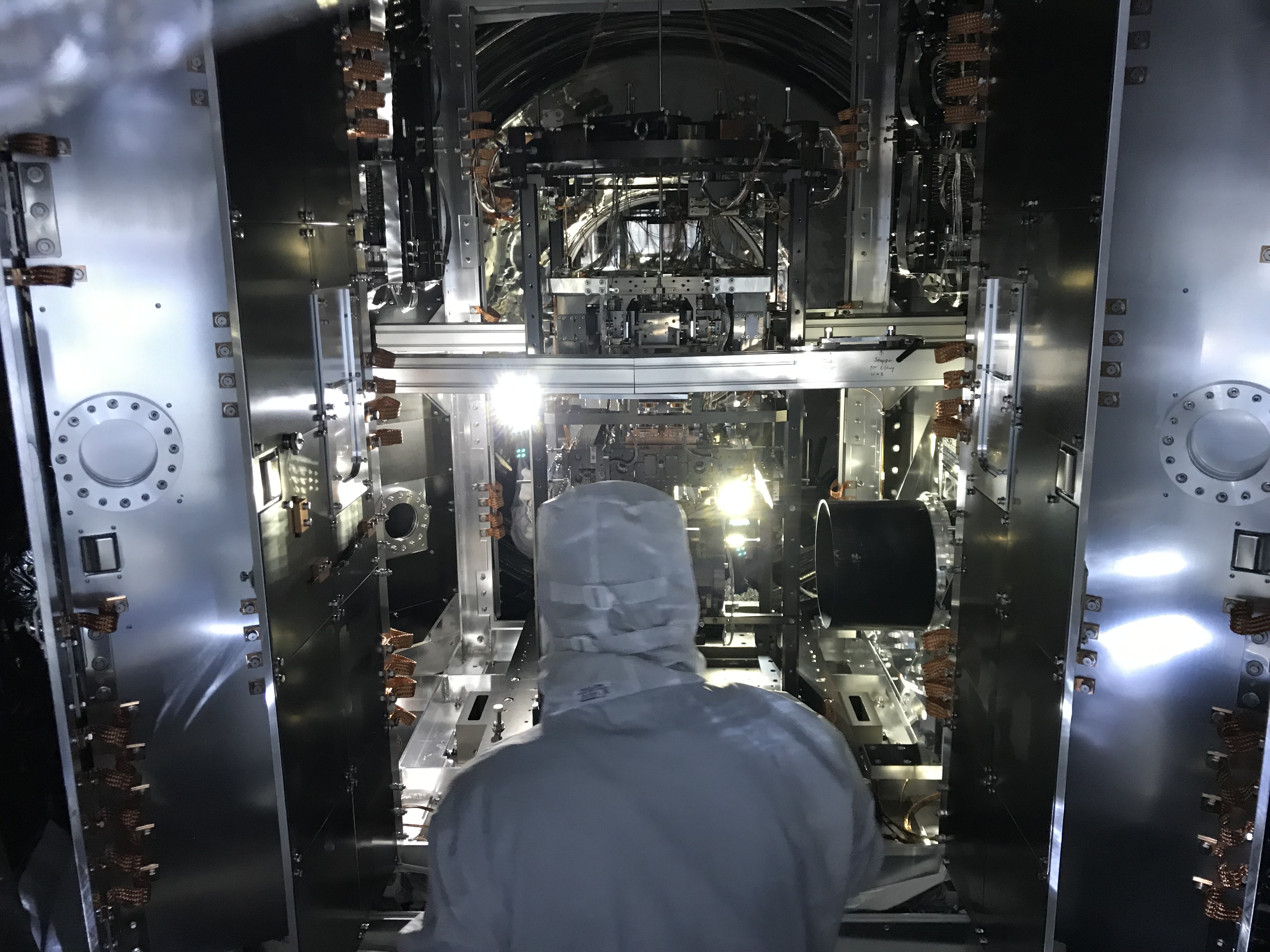
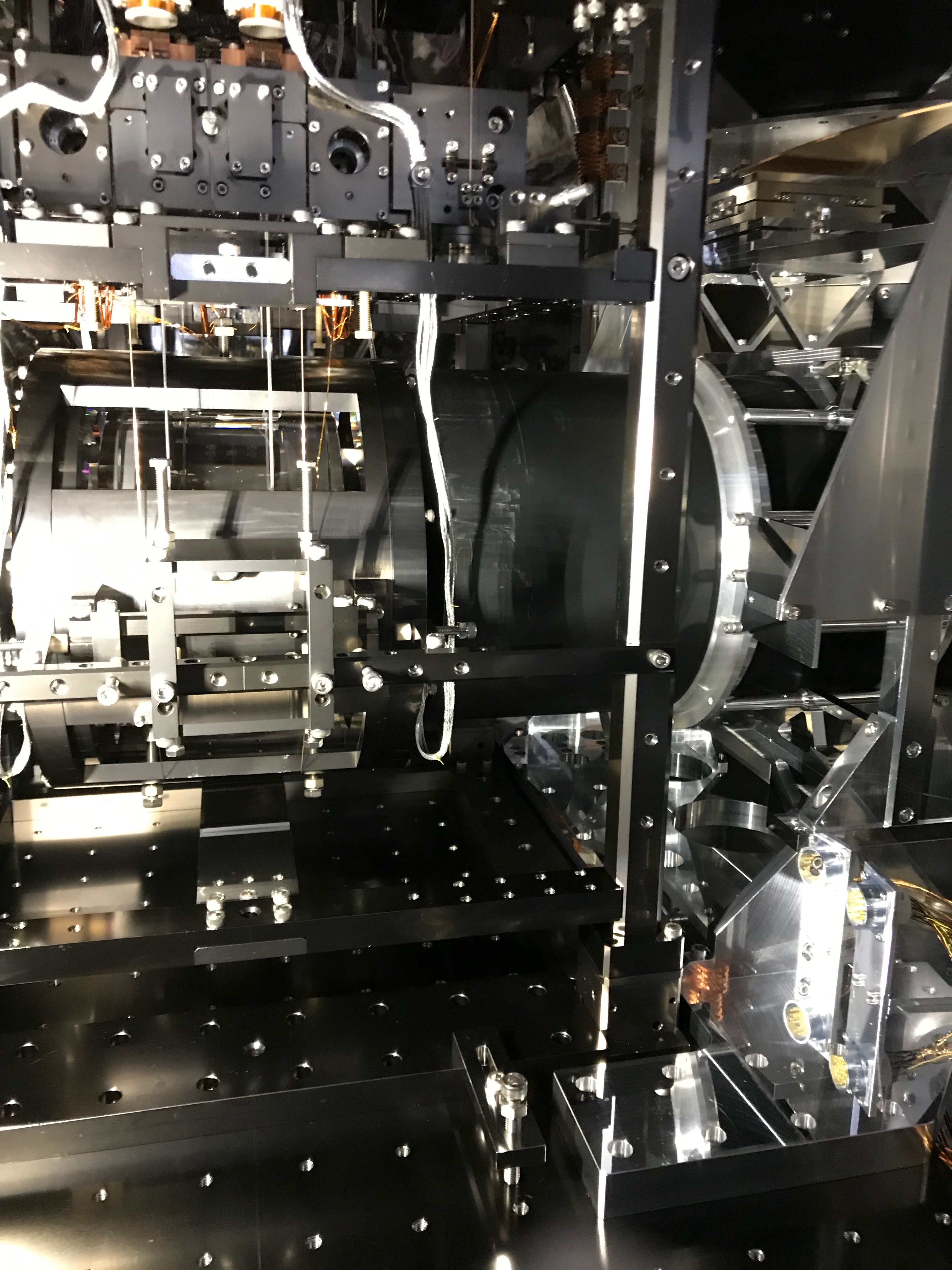
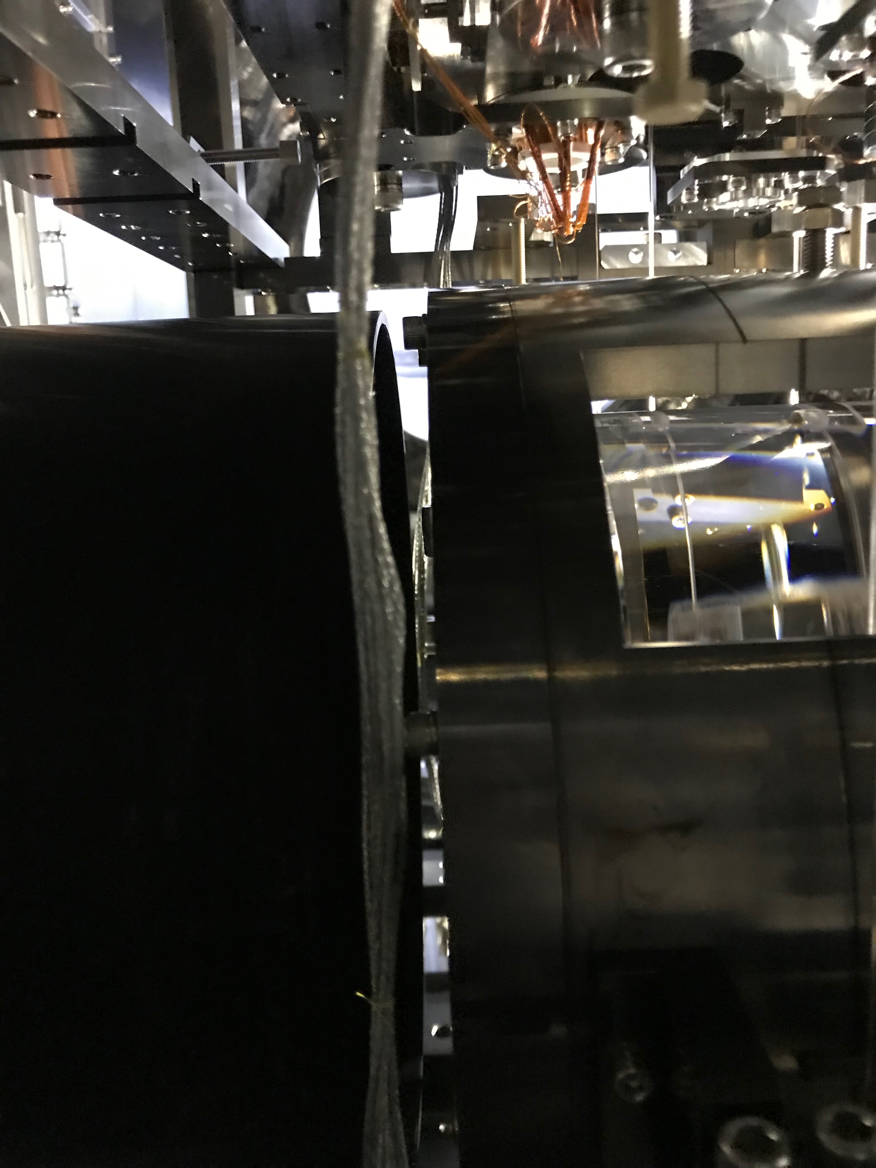
- Then detached the flange protectors that were attached at the front edge of the WAB (Fig 2 and 3).
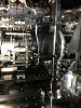
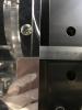
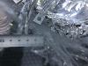
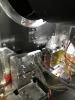
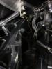
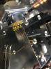
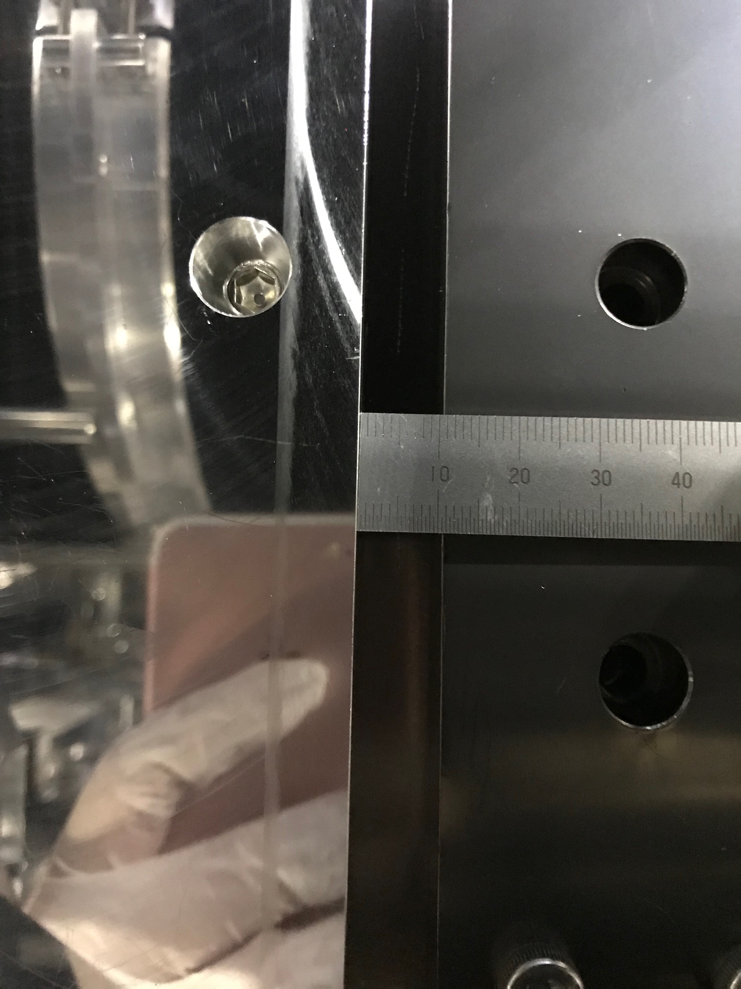
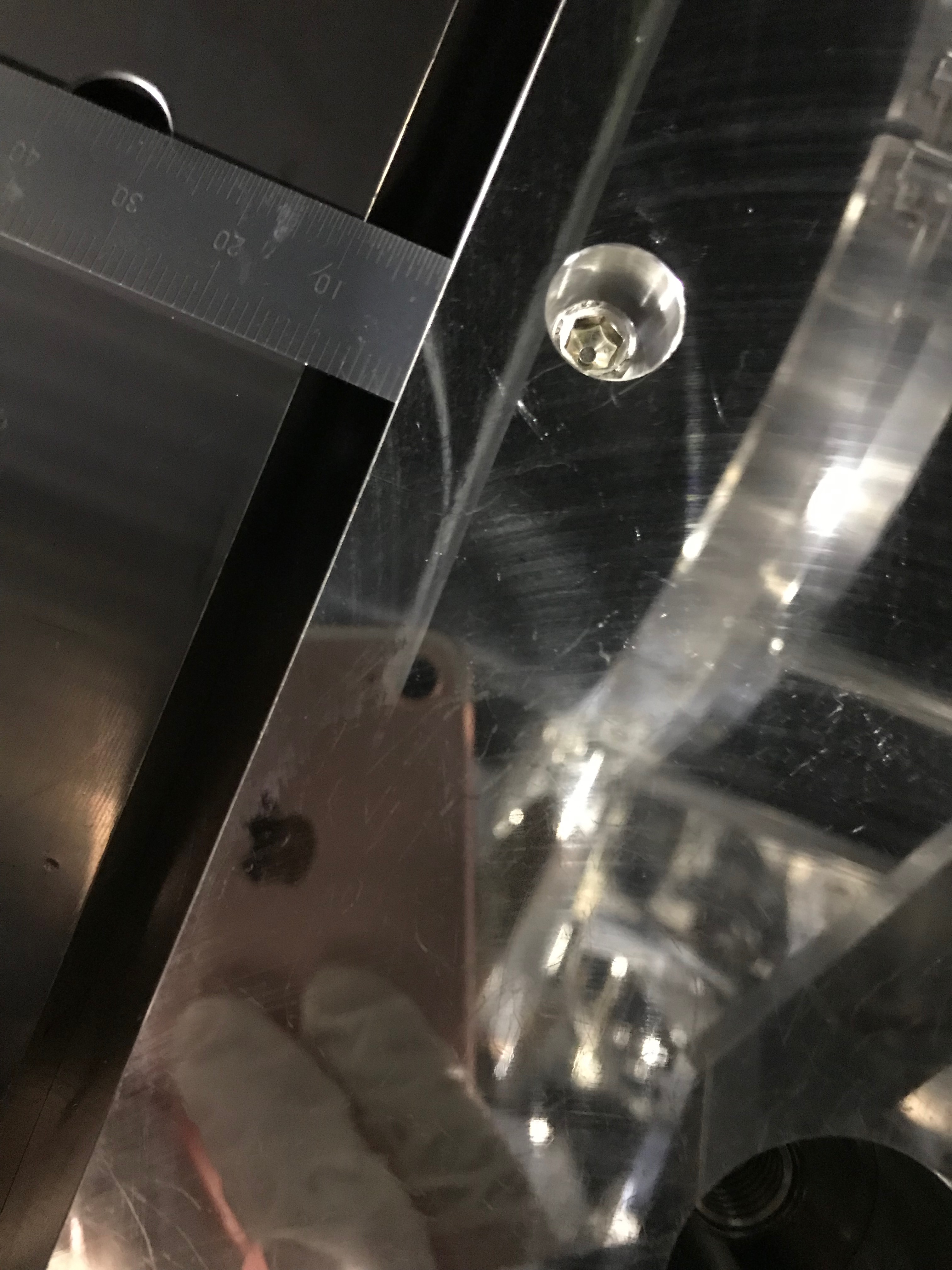
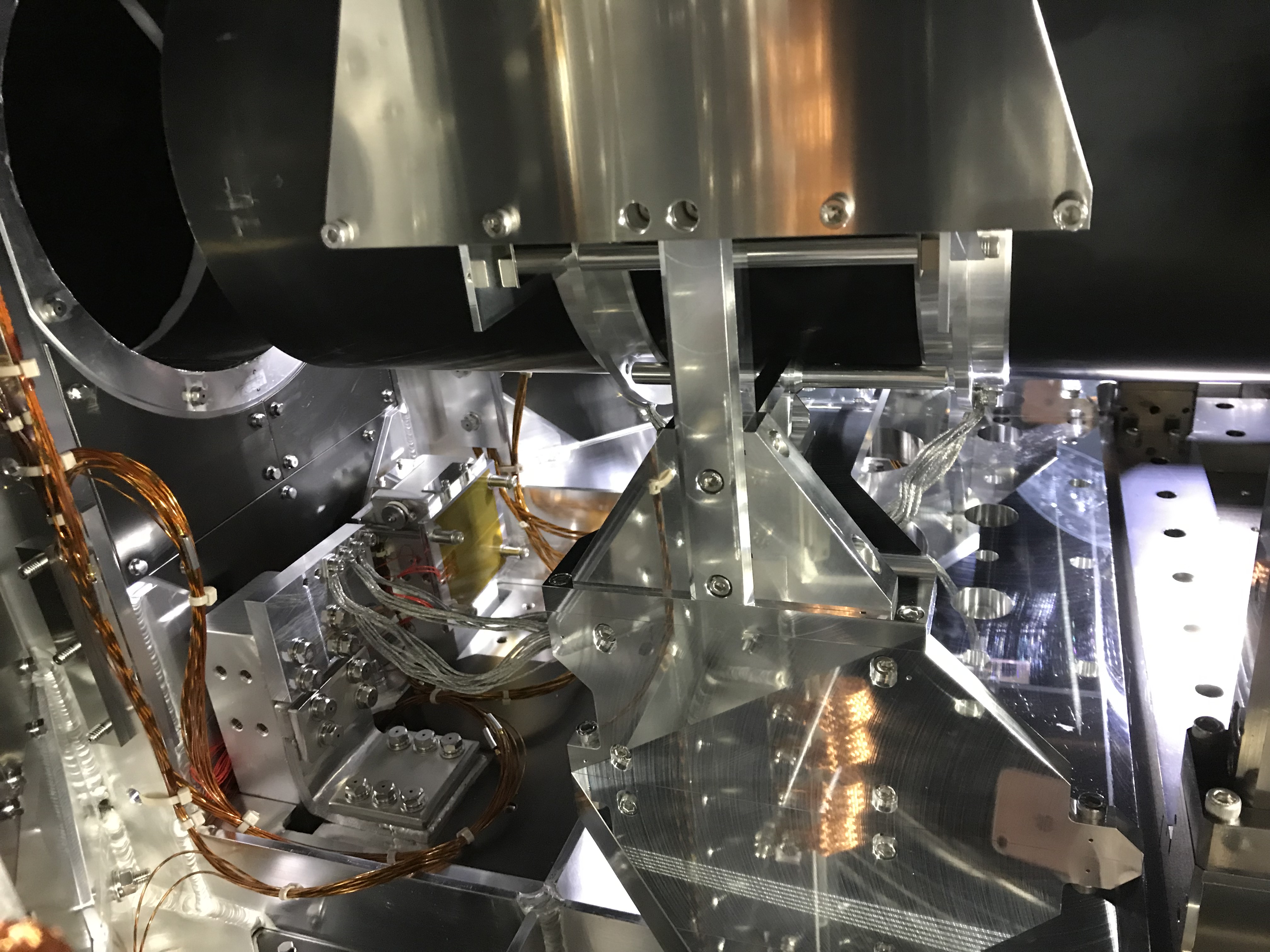
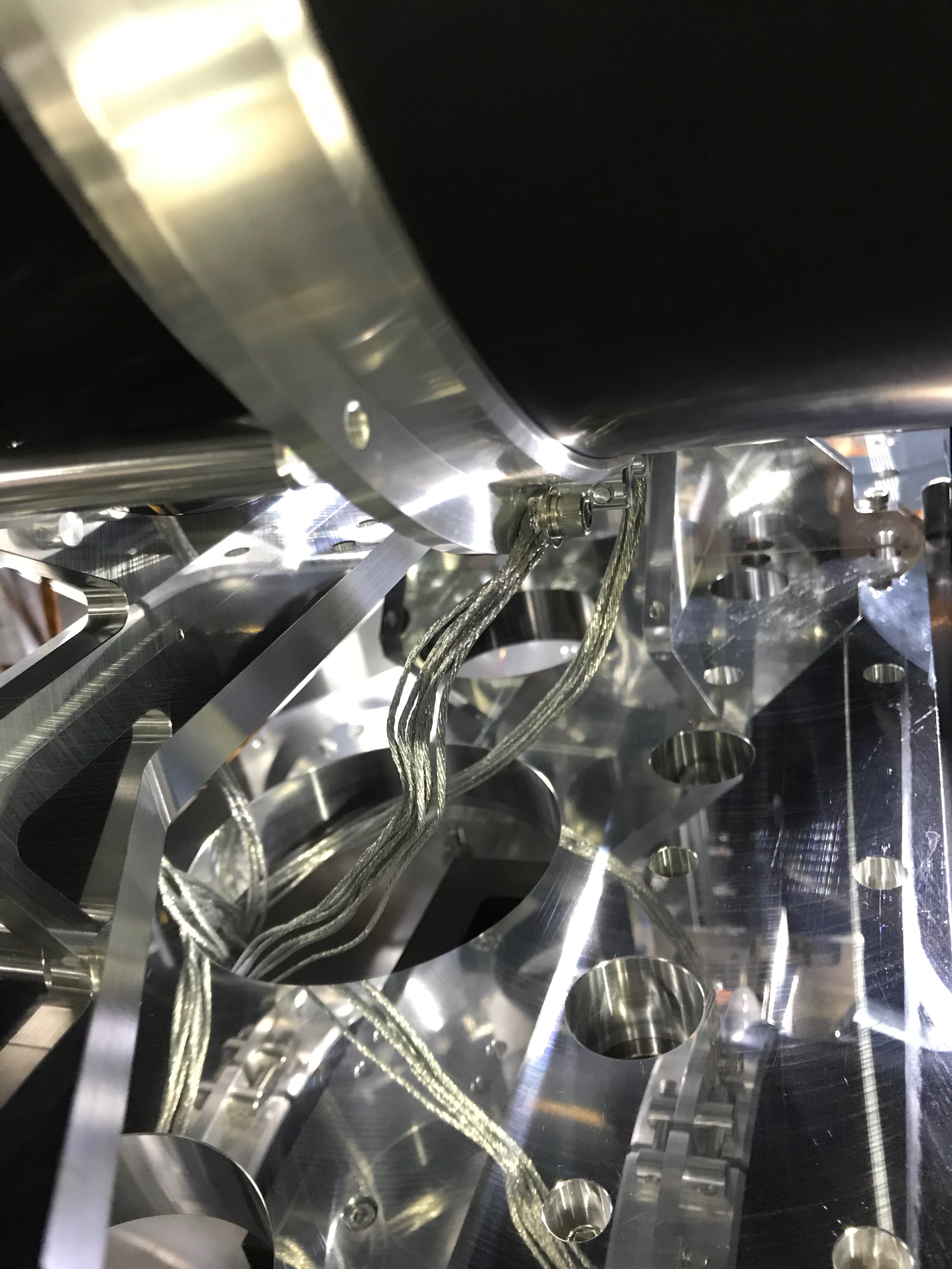
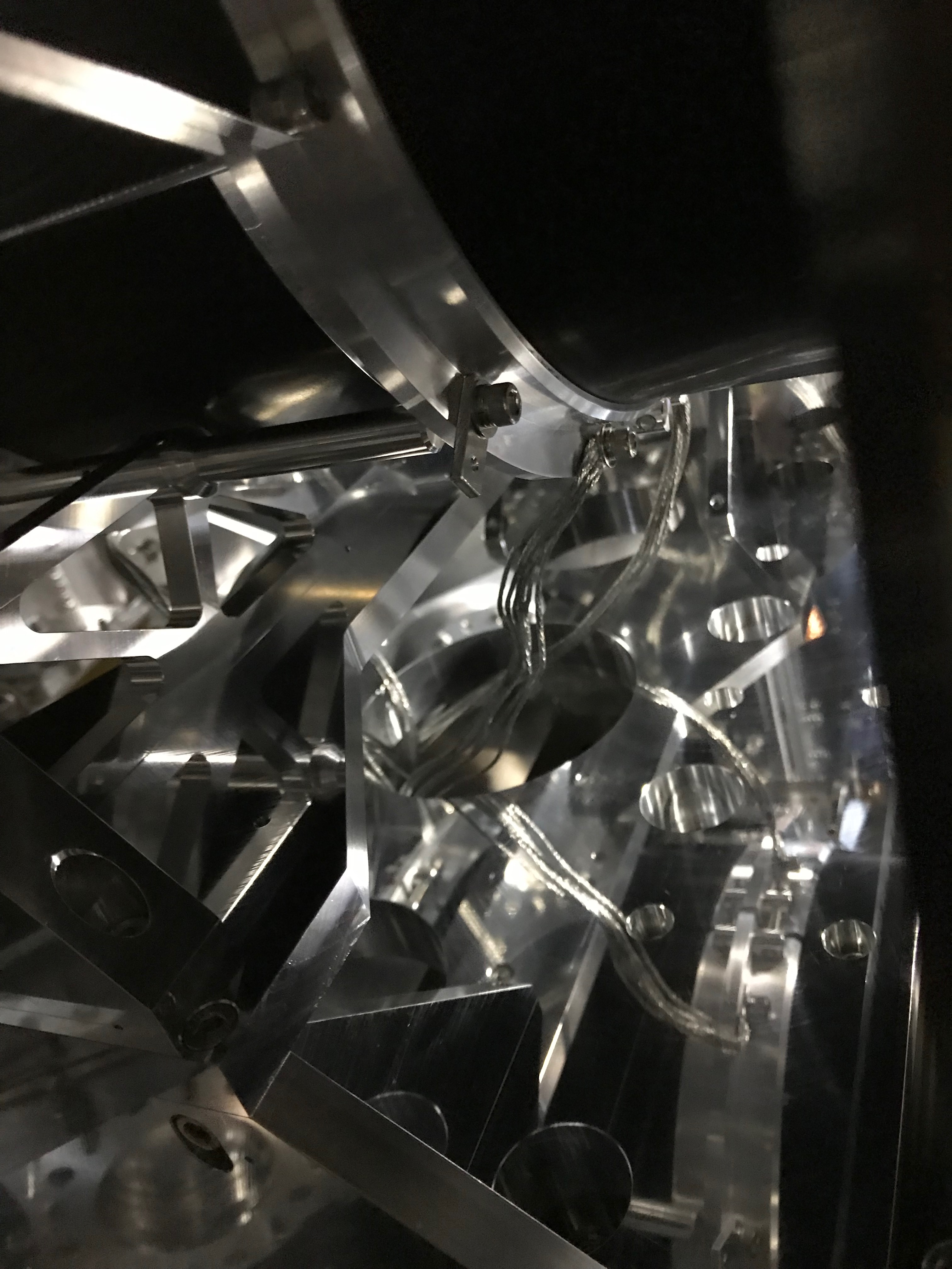
- Set up the WAB traverser, and lifted up the WAB suspension, and transported it to the nominal position (Fig 4 and 5). This time we could use the originally planned M6 narrow-cap screws to fix the base plate to the breadboard with a sufficient gap of about 10mm from the cryopayload (Fig 6); the gap could be estimated from the gap between the WAB base plate and the cryopayload's security frame (Fig 7 and 8).
- After dismantling the traverser setup from the cryostat, we attached several parts to the WAB and the suspension and so on as follows.
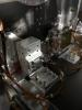
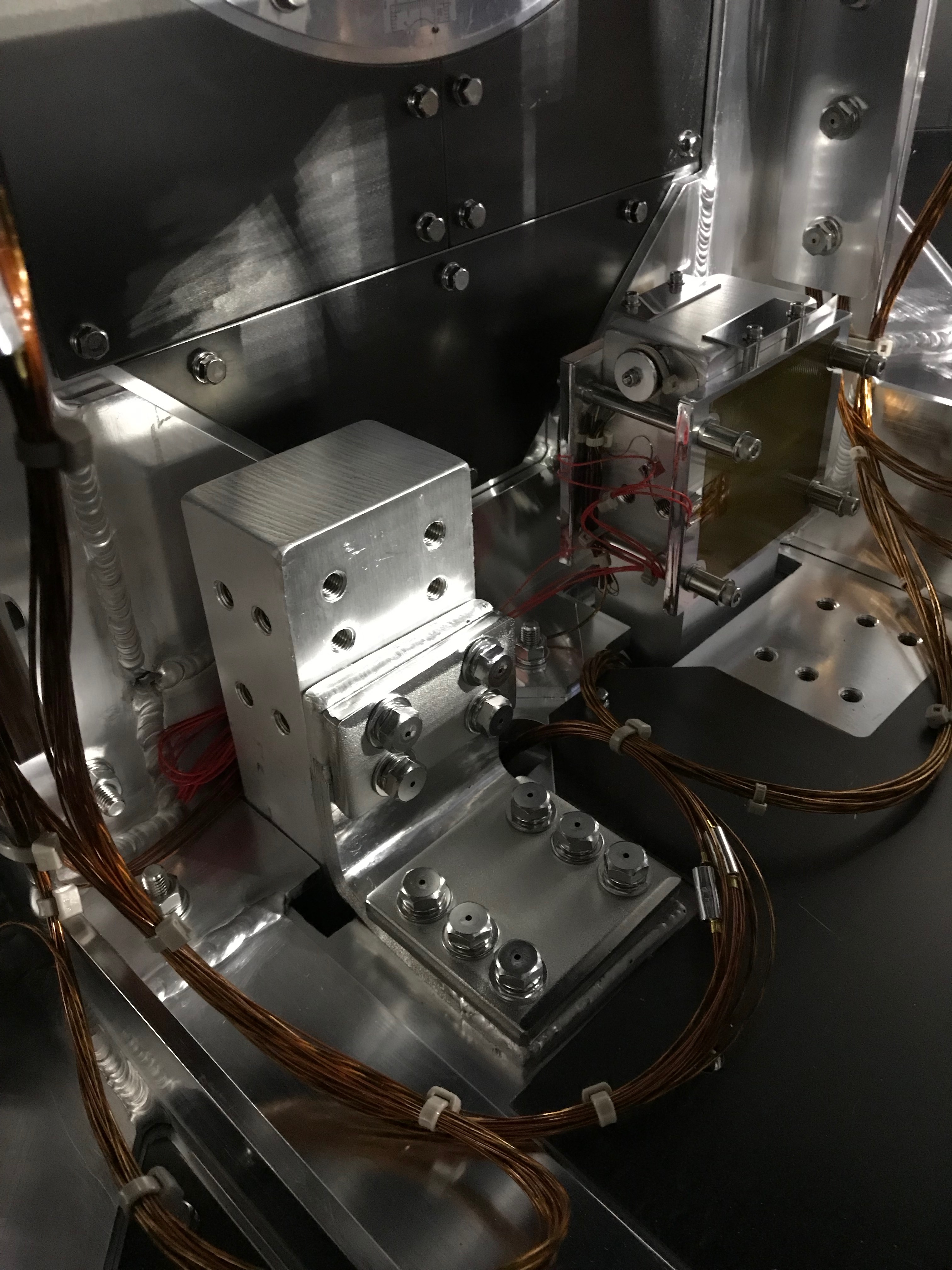
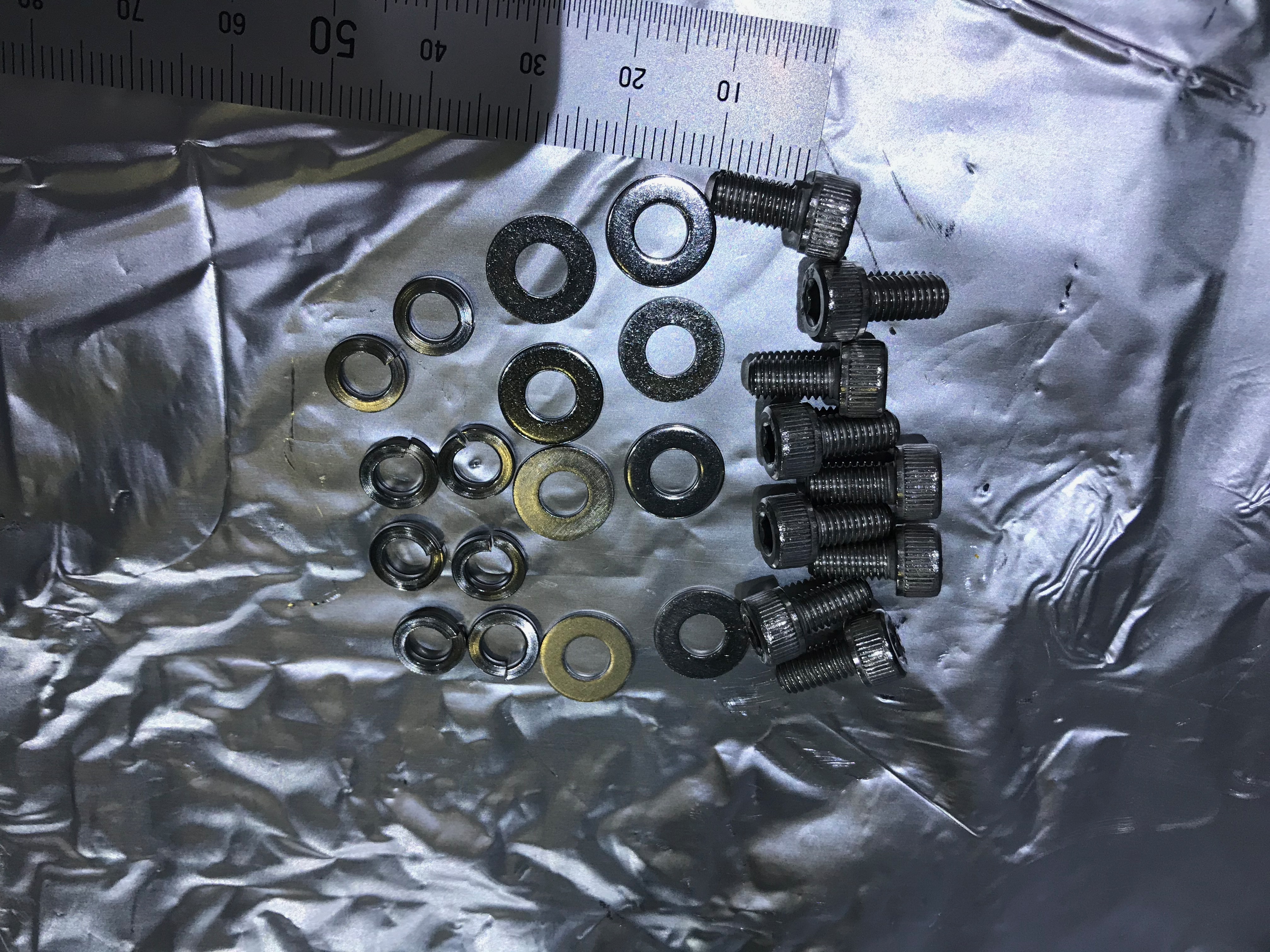
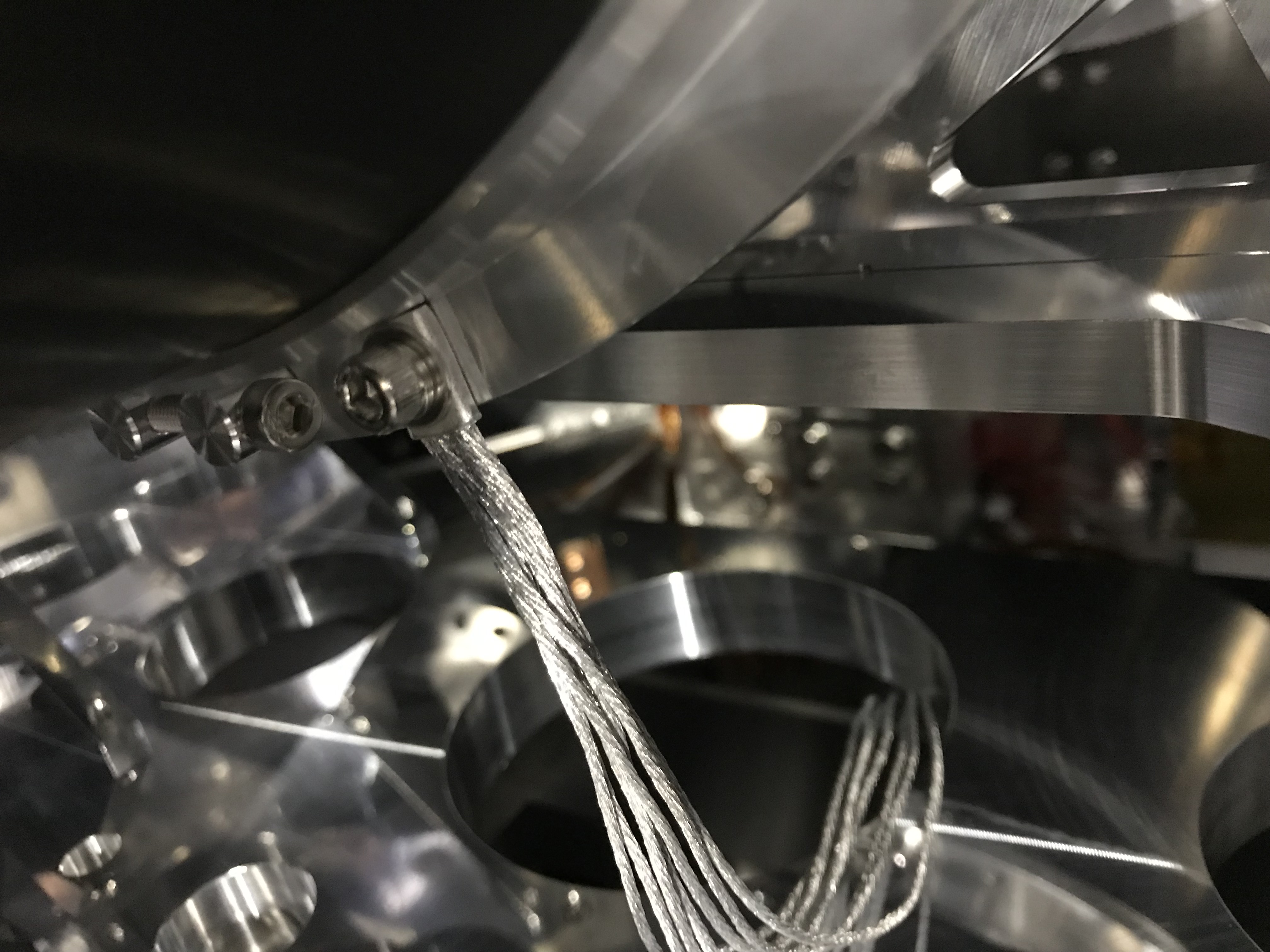
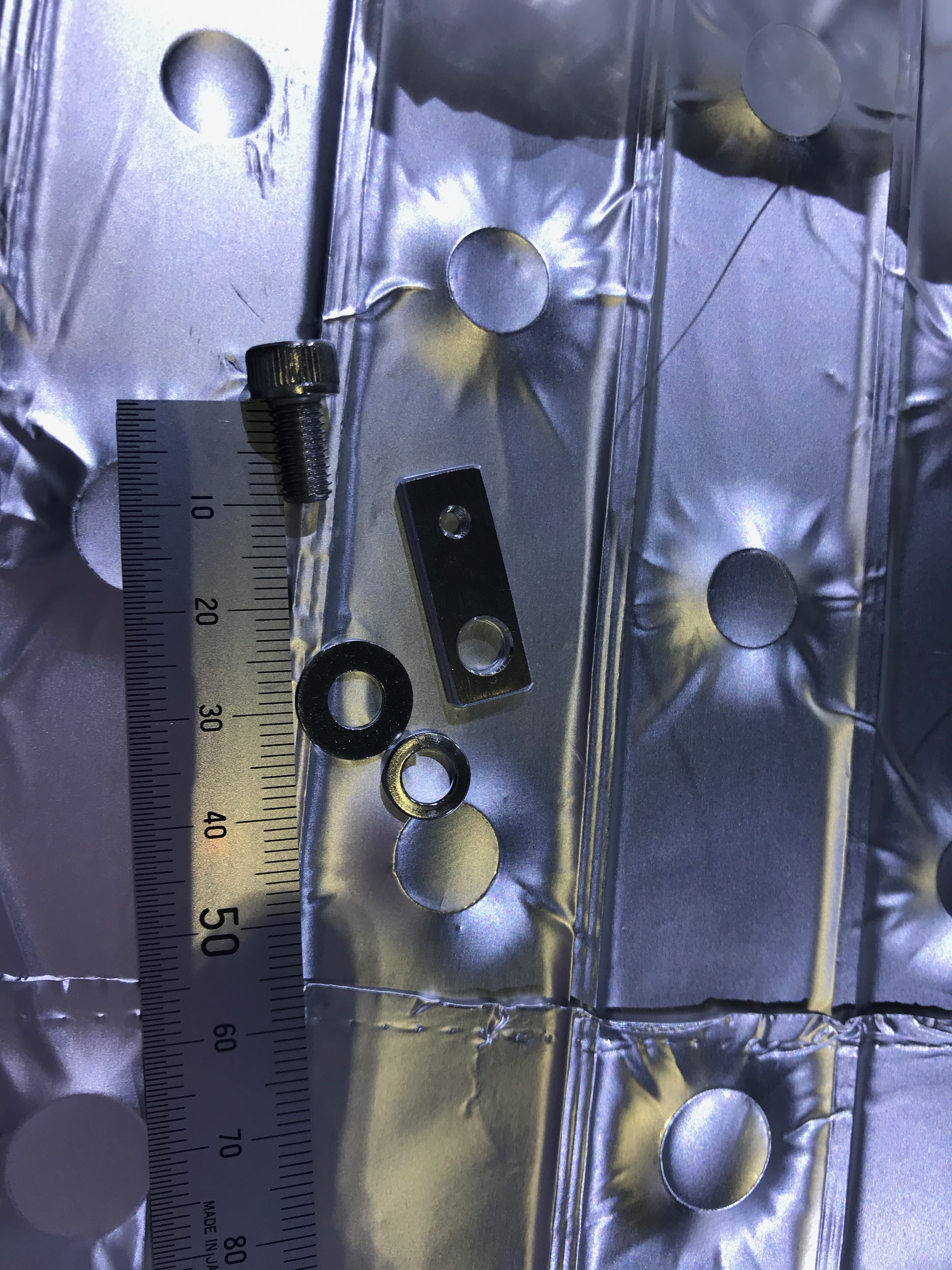
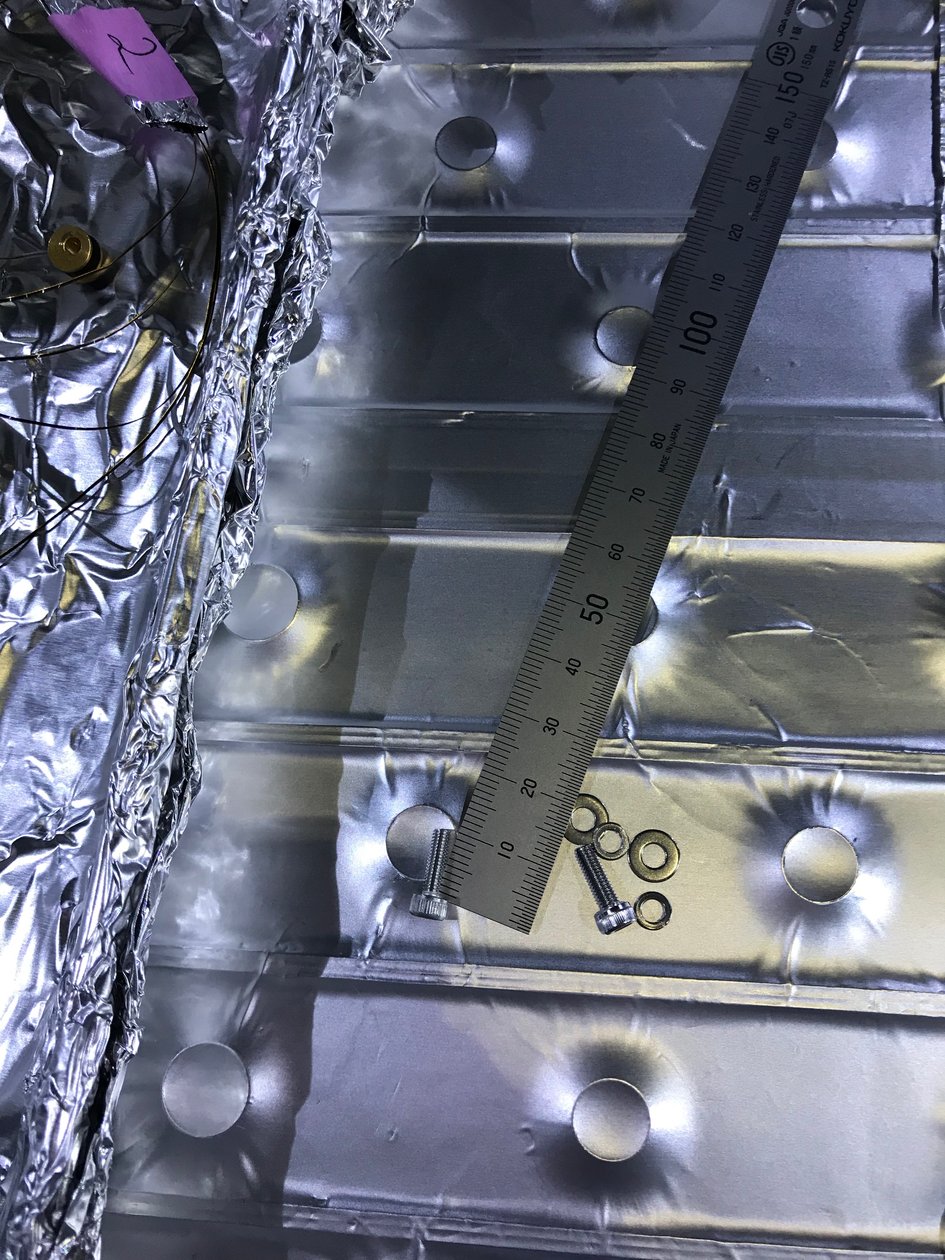
- Adapter block to the cooler head: an adapter block, which will interface four 6N Al heat links from the WAB and the cooler head, was attached to the cooler head. Four M8-40 screws, the plain washers, and the spring washers were used, and the final torque of 15Nm (5-> 10-> 15) was applied to each by a torque wrench (Fig 9-11).
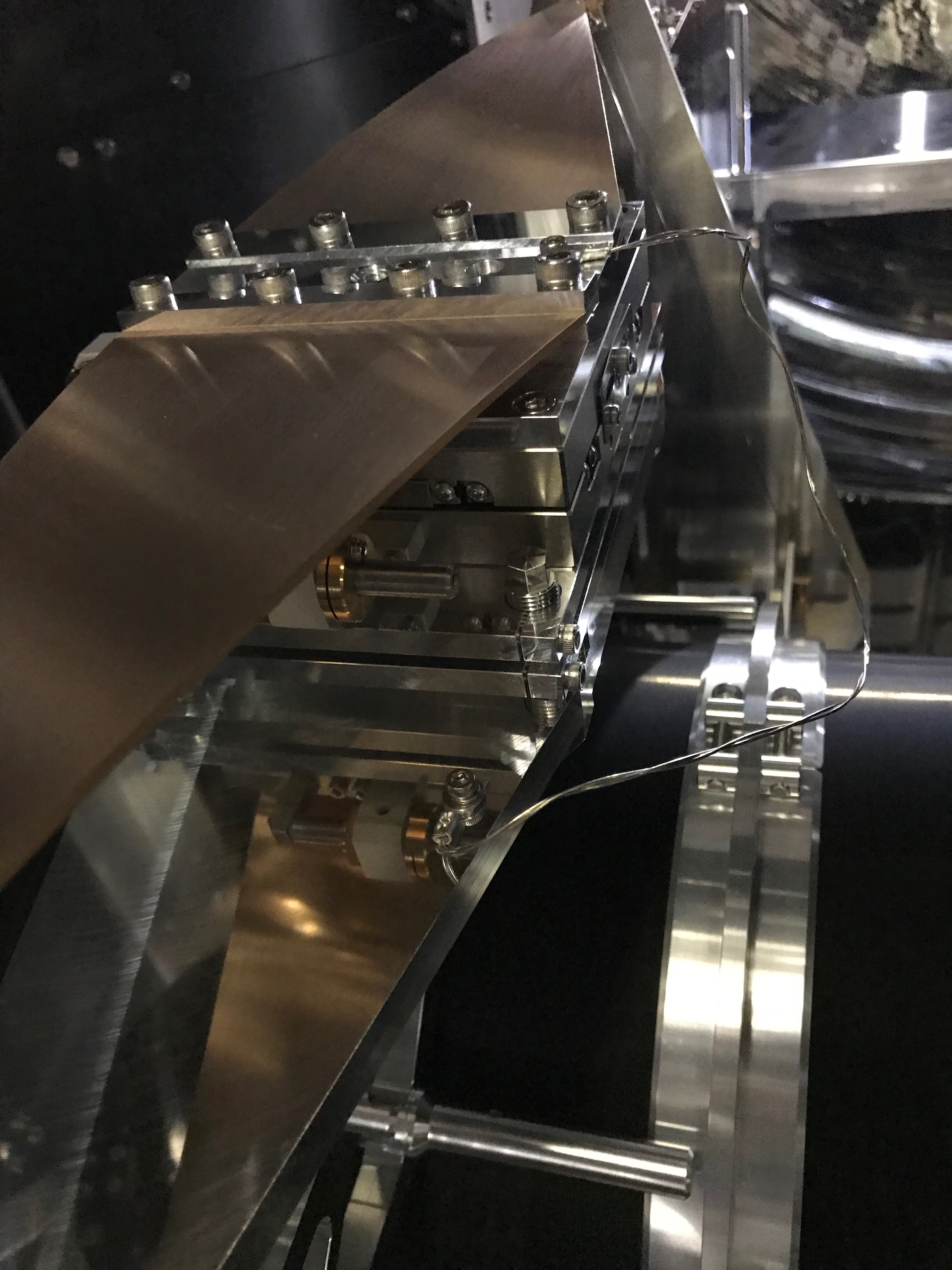
- 6N Al heat links: four 6N Al heat links were connected to the adapter block and the dual flanges of the WAB (Fig 12-17). Four M5-10 screws, the plain washers, and the spring washers were used to fix the tags of the heat links to the WAB flanges, and the final torque of 5Nm was applied to each by a torque wrench. In the same manner, four M5-10 screws, the plain washers, and the spring washers were used to fix the tags of the heat links to the adapter block, and the final torque of 5Nm was applied to each by a torque wrench. When I fixed the tags to the adapter block, the tags tended to rotate during screwing, so we somehow stop them rotating as much as possible.
- Flange tag for a thermomter: a tag for a thermomter for one of the WAB flange was also attached (Fig 18 and 19). An M5-10 screw, the plain washer, and the spring washer were used. The troque was 5Nm as well.
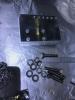
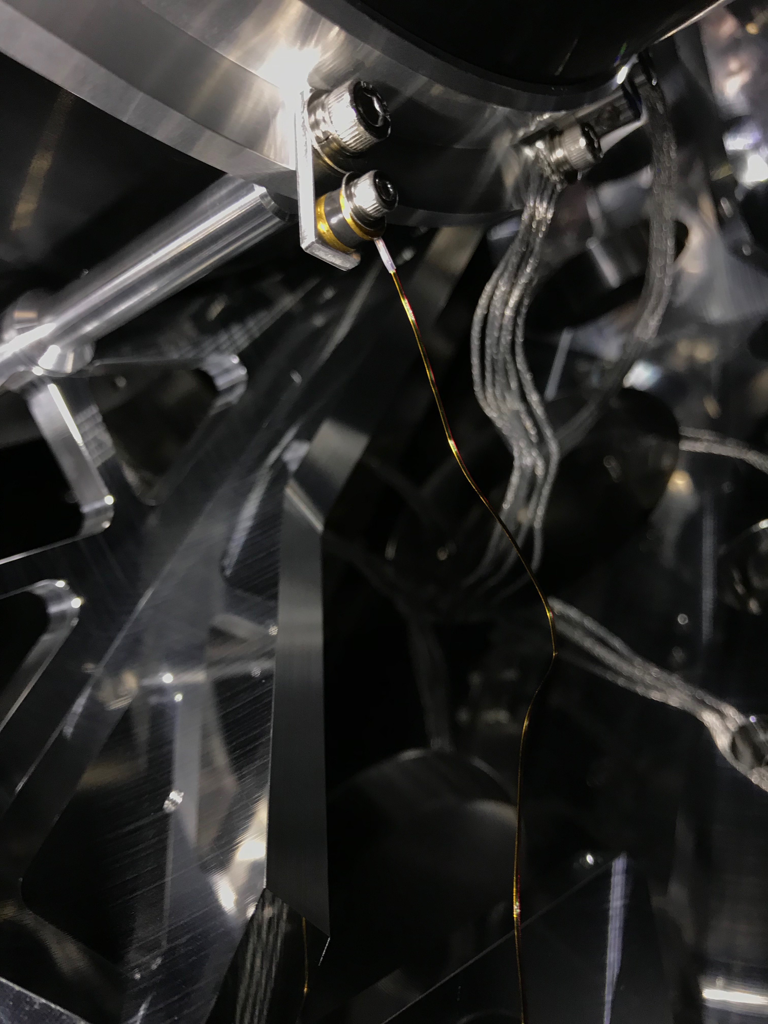
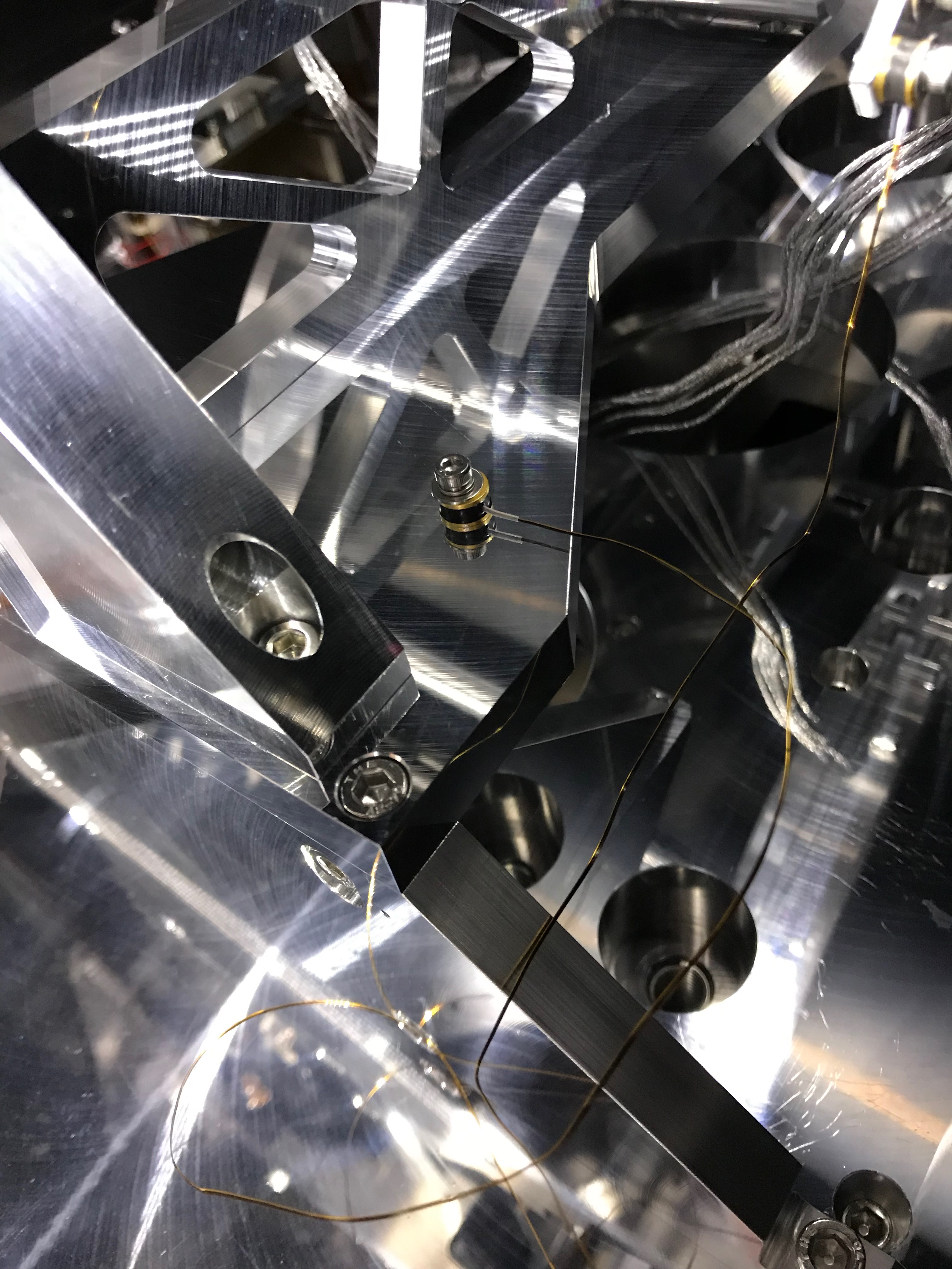
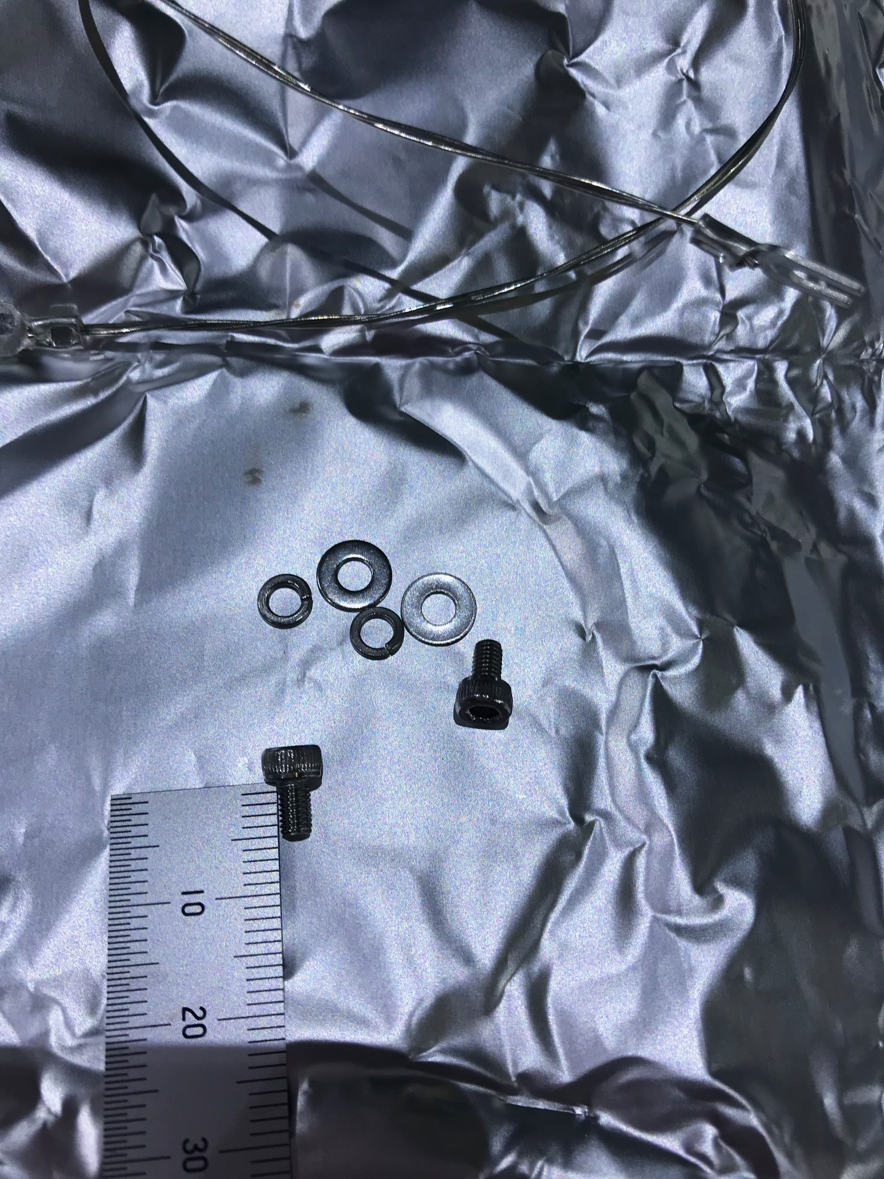
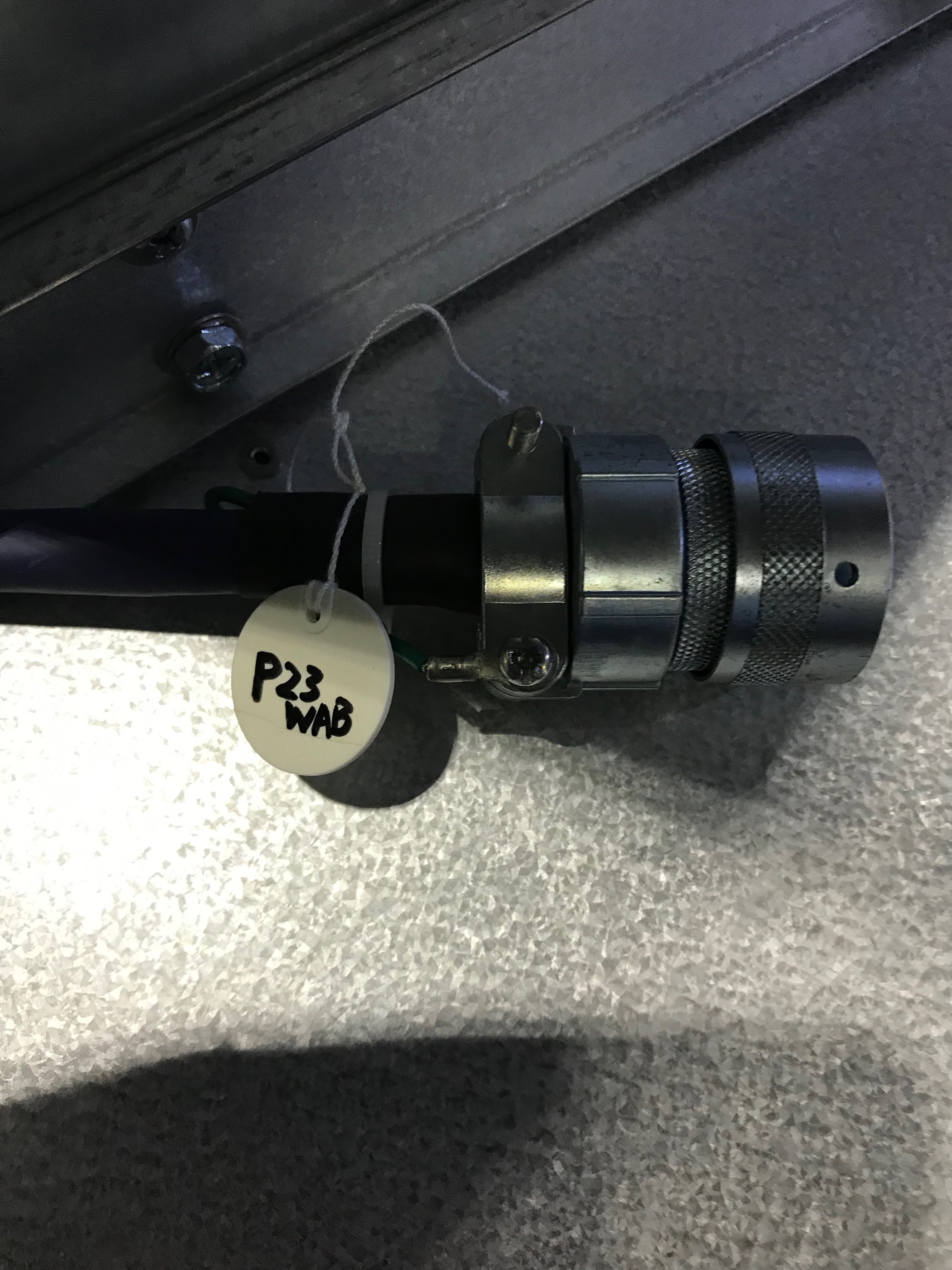
- Thermometers: two thermometers (LakeShore DT-670B-CU) were attached to the WAB and the suspension structure (Fig 20 and 21); one (S/N#2564, which was called #1 during the WAB cooling test last year) for the WAB, one (S/N#360, which was called #2 during the WAB cooling test last year) for the suspension structure. For each, an M3-10 screw, the washer, and the spring washer were used. (Torque wrench was not used.) S/N 2564
Note: we could not insert support blocks under the bottom of the base plate today, and that will be done later.

