Reports 1-1 of 1 Clear search Modify search
AOS (Beam Reducing Telescopes)
masayuki.nakano - 18:24 Wednesday 26 December 2018 (7502) Print this report
Beam profile measurement on the TMSX table

[Enomoto, Nakano]

We measured the beam profile and the laser power on the TMSX optical table for the IR and the GR. The result is as bellow.

1. Laser power (IR only)

70(6) uW

2. Beam profile

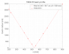
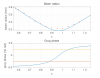
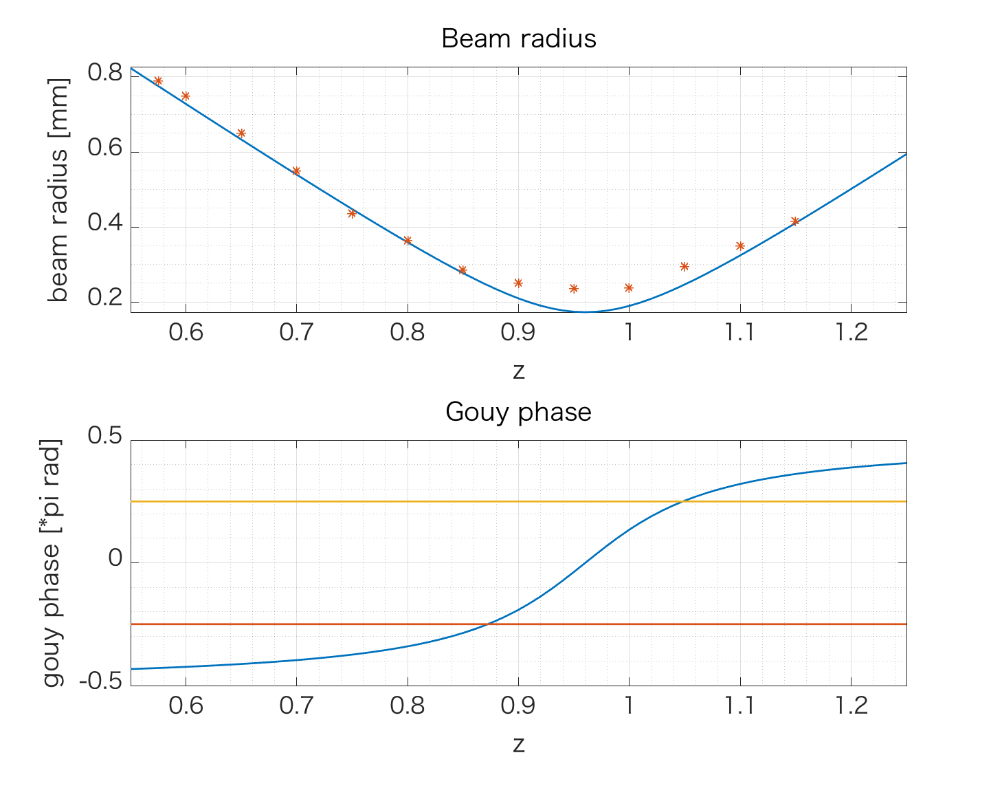
IR: w0 = 36.1(1), z0 = 529.3(8) mm from the RST2 (second steering mirror after the periscope)
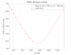
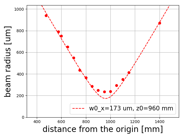
GR: w0 = 168(2) um, z0 = 746(6) mm from the GST1 (first steering mirror after the periscope)
Fig.1, 2 show the measurement result and the Fig.3, 4 show the picture of the measurements. The result is consistent with the design of the TMS. However, the second lens should be adjusted finely to realize the guoy phase telescope.
 

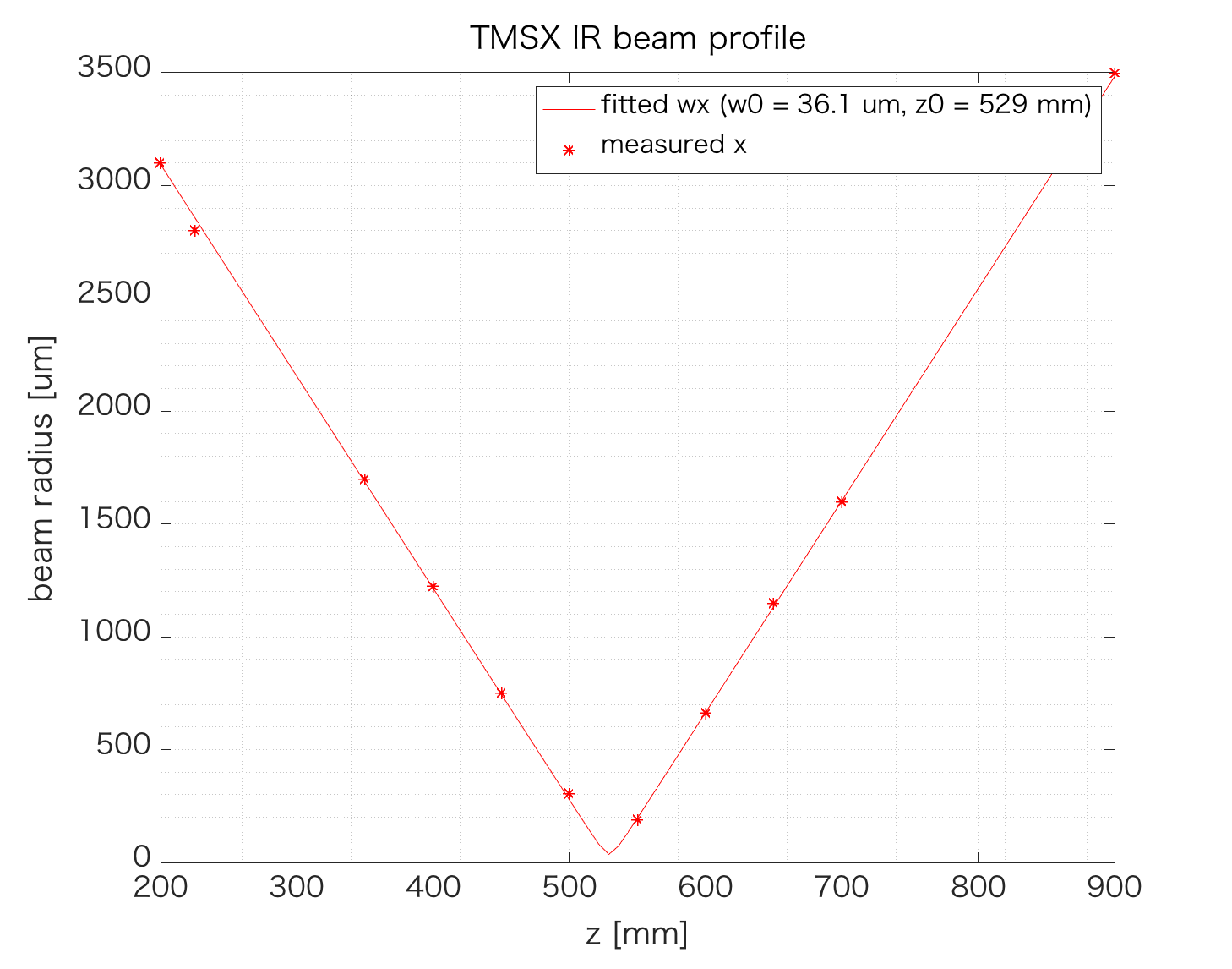
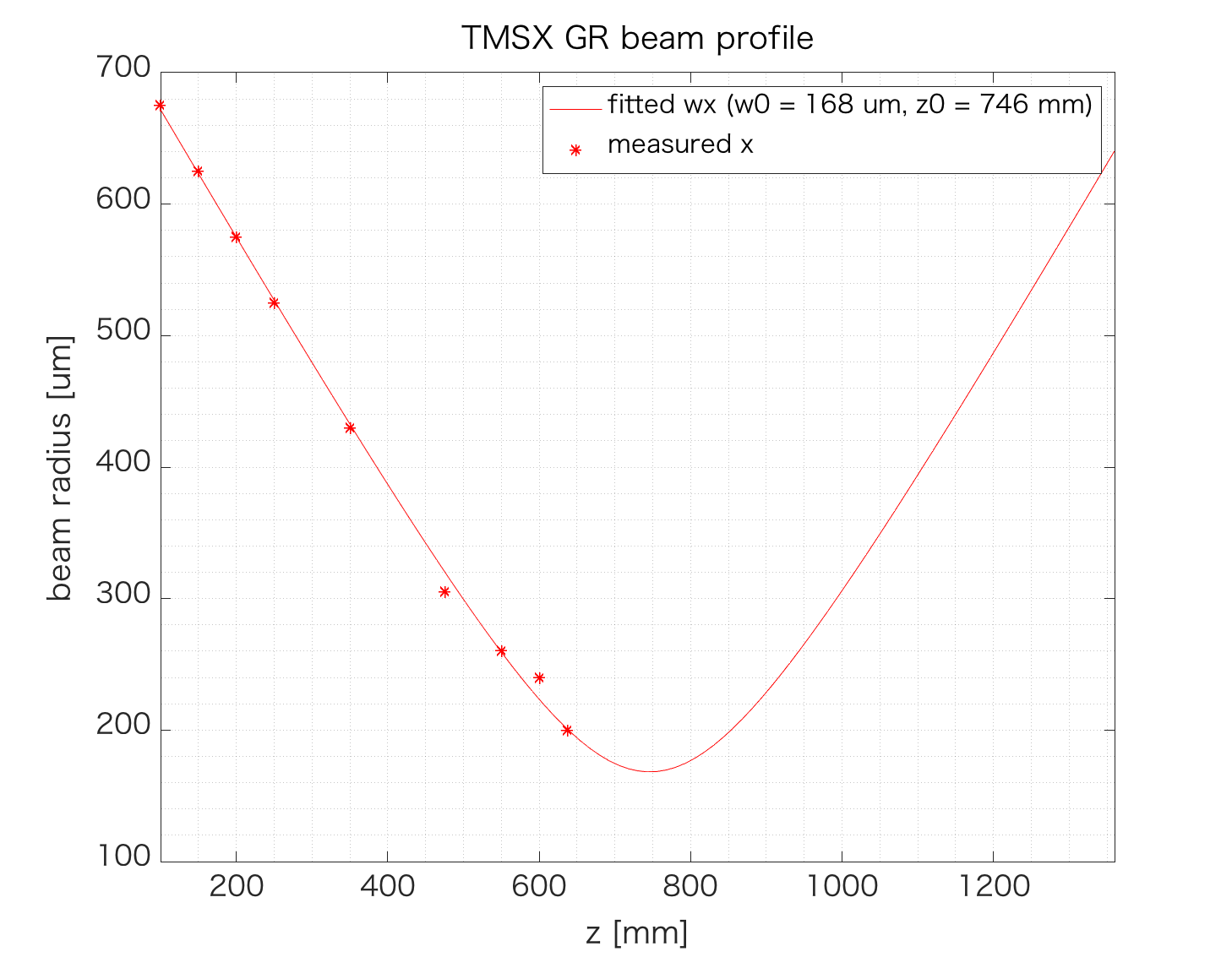
Fig.1 Beam profile of the IR beam                                           Fig2. Beam profile of the GR beam


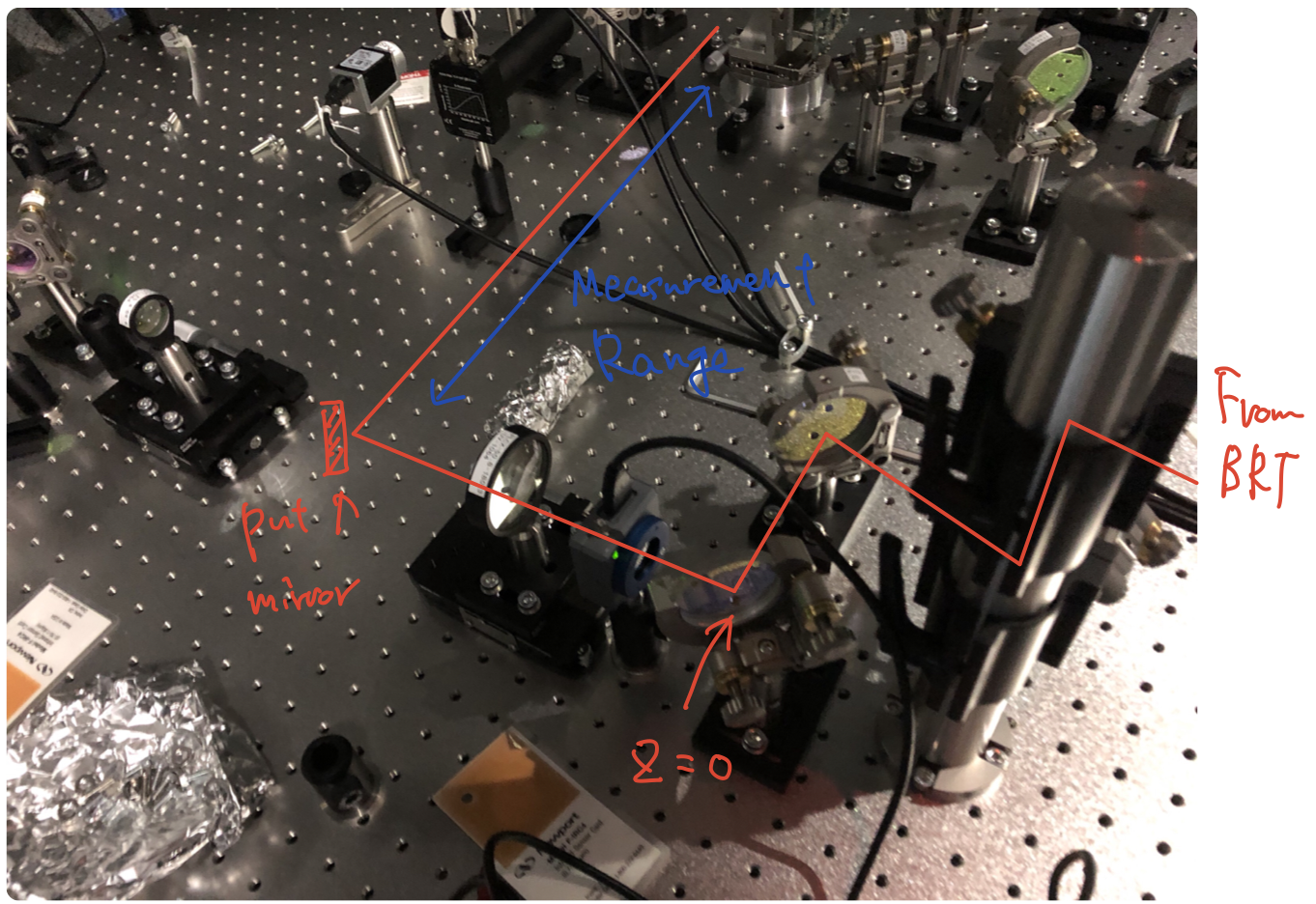
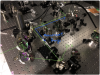
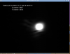
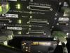
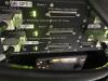
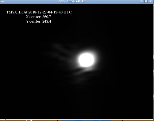
Fig3. The picture of the IR beam profile measurement       Fig4. The picture of the GR beam profile measurement

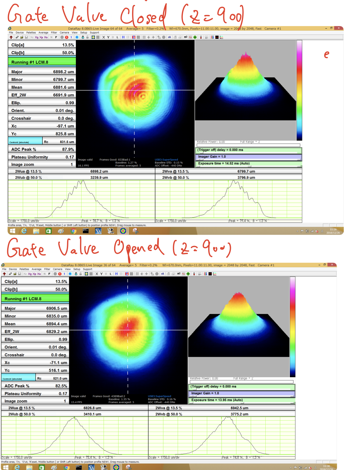
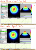
3. Beam shape check with the gate valve open/closed

The beam shape was checked before and after the GV between the EXT chamber and the EXC chamber open. The beam size does not change, but the circular fringe pattern disappeared after opening the GV. Fig5 shows the beam shape with/without the GV.
There seems to be clipping at the upper left even after opening GV. 

Images attached to this report
Comments to this report:
masayuki.nakano - 11:09 Friday 28 December 2018 (7527) Print this report

[Enomoto, Nakano]

We adjusted the gouy phase of the injection IR-beam into the QPDs. Firstly, we adjusted the position of the second lens (RMSL2) so that the beam position located 1 m from the RST2. Then, we measured the beam profile. The attached figure shows the beam size and the gouy phase. The fitting seems not good around the beam waist. This is because the beam was too small compared to the resolution of the beam profiler. The Rayleigh range of this beam calculated from the fitting is 89 mm. Therefore, the QPDs was put at the position of +/- 89 mm from the beam waist position z = 960.

At the same time, we moved the camera to the position near the beam waist. The attached picture shows the image of the new TMS IR camera.

Images attached to this comment
yutaro.enomoto - 18:21 Friday 28 December 2018 (7536) Print this report

SInce Dsub-15 pin cables from the IR QPDs were not connected to the QPD interface board for IR QPD, but to the interface labeled as Oplev,
we unplugged the cables and connected them to the correct QPD interface. See the pictures for how it looks like before and after this work.

Images attached to this comment
koji.nagano - 22:30 Friday 28 December 2018 (7539) Print this report

Thank you for your work.
Did you reconnect the output cables (i.e. back side ones) also?

yutaro.enomoto - 12:57 Saturday 05 January 2019 (7574) Print this report

Super late report:
Here is the beam profile after we shifted the position of the lens.

Images attached to this comment
Non-image files attached to this comment
Search Help
×

Warning

×