[Lucia, Y. Fujii, Eleonora]
We have implemented a first version of the inertial damping for the IP of the ITMX.
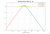
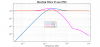
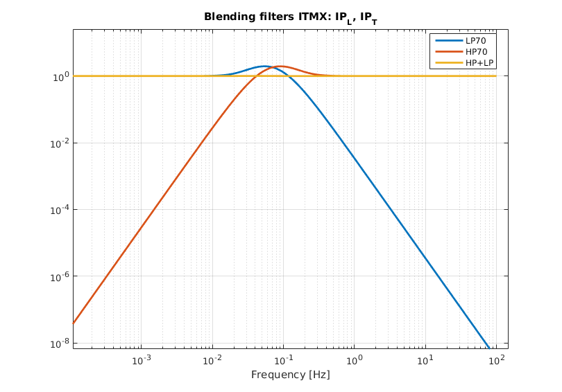
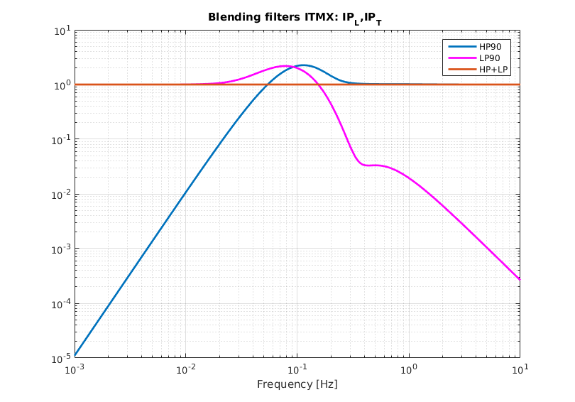
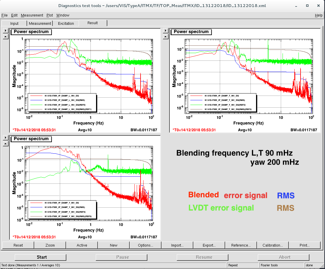
We set two possible HP/LP combinations (for L and T) with crossing frequency at 70 mHz and 90 mHz respectively and one at 200 mHz for Yaw.
The filter shapes are shown in pic 1, 2, 3 and the poles/zero lists are reported below.
The control filters have also been adjusted to increase the bandwith. The UFG now is about 1 Hz.
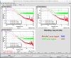
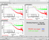
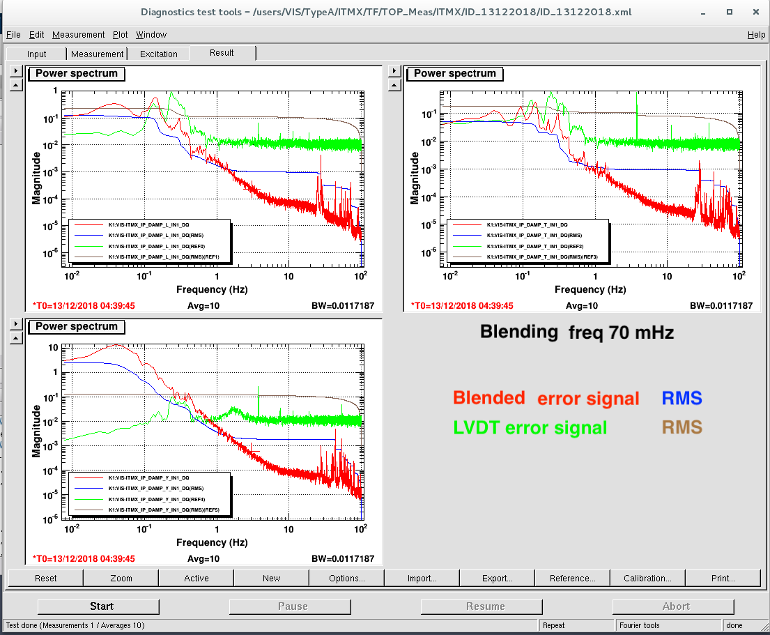
We compared the spectrum of the error signal when the loop was closed using only LVDT with those using the blendend signal with accelerometers.
It seems that the we can reduce the seismic noise reinjected in L and T but in the case of Yaw the noise at low frequency increases. Therefore we decided keep the control of YAW only with LVDT position control.
The loops could be closed smoothly but sometimes a quite narrow oscillation at the blending frequency appears. It might be due to a loop instabilty caused by a mismatching of the phase at the crossing. To be investigated..
LOW PASS 70 mHz
| Freq | Q | pole/zero |
| 0.07 | 0.5 | pole |
| 0.07 | 0.5 | pole |
| 0.07 | 0 | pole |
| 0.0221 | 0.6325 | zero |
| GAIN | 1 @ in DC |
HIGH PASS 70 mHz
| Freq | Q | pole/zero |
| 0.07 | 0.5 | pole |
| 0.07 | 0.5 | pole |
| 0.07 | 0 | pole |
| 0 | 0 | zero |
| 0.2214 | 0.6325 | zero |
| GAIN | 0.045 @ 14.16 |
LOW PASS 90 mHz
| Freq | Q | pole/zero |
| 0.12 | 0.5 | pole |
| 0.12 | 0.5 | pole |
| 0.12 | 0 | pole |
| 0.25 | 0 | pole |
| 0.25 | 2 | pole |
| 0.35 | 2 | zero |
| 0.35 | 1.1 | zero |
| 0.0313 | 0.6442 | zero |
| GAIN | 1 @ DC |
HIGH PASS 90 mHz
| Freq | Q | pole/zero |
| 0.12 | 0.5 | pole |
| 0.12 | 0.5 | pole |
| 0.12 | 0 | pole |
| 0.25 | 0.5 | pole |
| 0.25 | 0 | pole |
| 0.5879 | 0 | zero |
| 0.3682 | 0.6727 | zero |
| 0.2321 | 1.0808 | zero |
| 0 | 0 | zero |
| GAIN | 8.679 @ 0.055 |
LOW PASS 200 mHz YAW
| Freq | Q | pole/zero |
| 0.2 | 0.5 | pole |
| 0.2 | 0.5 | pole |
| 0.2 | 0 | pole |
| 2 | 0.5 | pole |
| 2 | 0 | pole |
| 1.8 | 2 | zero |
| 1.8 | 0.5 | zero |
| 0.0629 | 0.6327 | zero |
| GAIN | 1@DC |
HIGH PASS 200 mHz YAW
| Freq | Q | pole/zero |
| 0.2 | 0.5 | pole |
| 0.2 | 0.5 | pole |
| 0.2 | 0 | pole |
| 2 | 0.5 | pole |
| 2 | 0 | pole |
| 2.2076 | 0 | zero |
| 1.9166 | 0.5 | zero |
| 0.6331 | 0.6581 | zero |
| GAIN | 0.1@1.85 |
Note: in the filter plots the HP have been designed assuming the accelerometer response is converted in displacement. When we actually implement it we have to remove a pair of zero in DC (as they are are already included in the response of the accelerometers) and adjust the gain accordinlgy.
