Reports 1-1 of 1 Clear search Modify search
MIF (ITF Control)
yutaro.enomoto - 21:40 Thursday 06 December 2018 (7289) Print this report
Summary of today's work

[Miyazaki, Enomoto]

Today we have done a couple of measurements and some trial. In this log, we would like to summarize what we did today.
The detailed analysis of the measurements will follow.

= Measuements =
Today's main goal was to see if we can do the measurements like these and to establish the method and procedure of them.
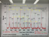
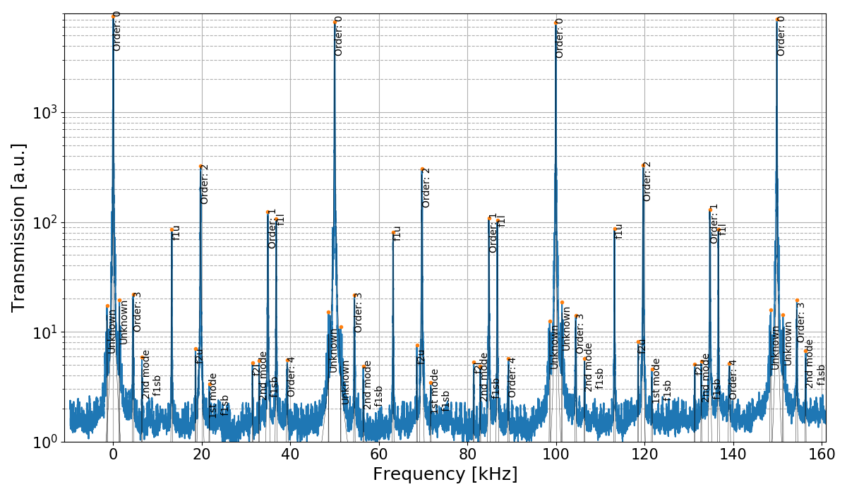
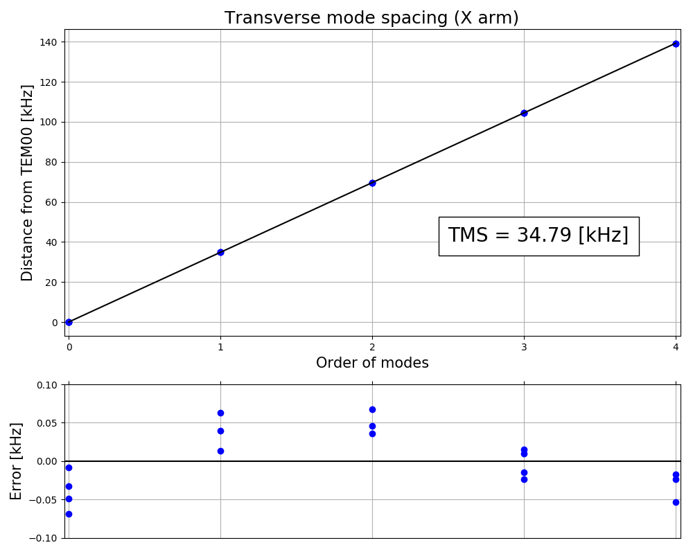
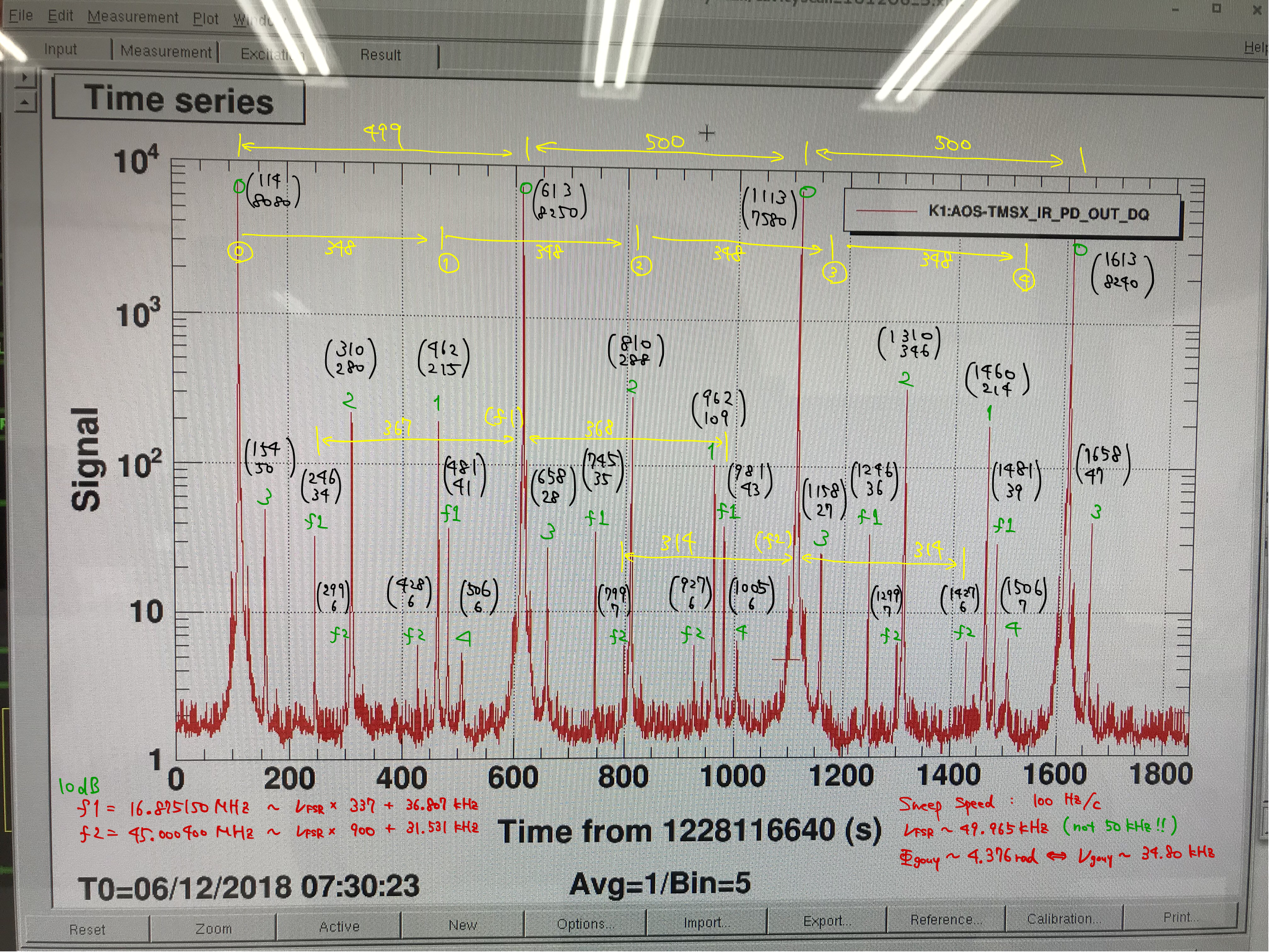
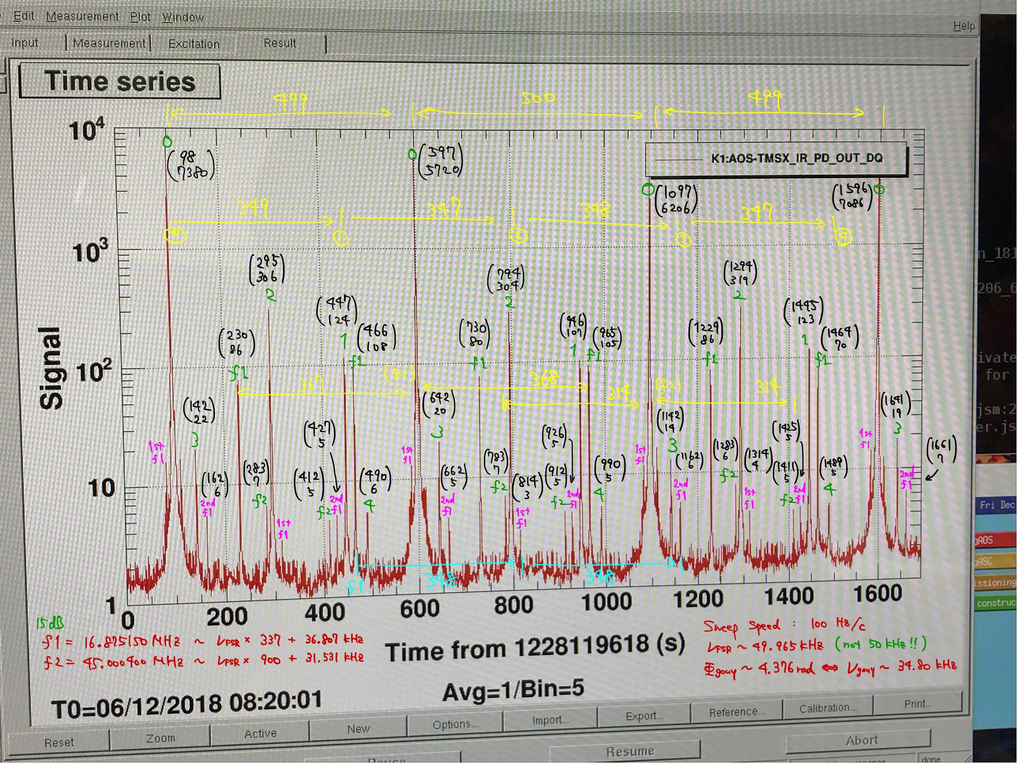
1. Cavity scan
While controlling the main laser frequency with respect to X arm cavity by ALS, we swept the main laser frequency by sweeping the PLL offset frequency.
We swept by more than 3 FSRs.

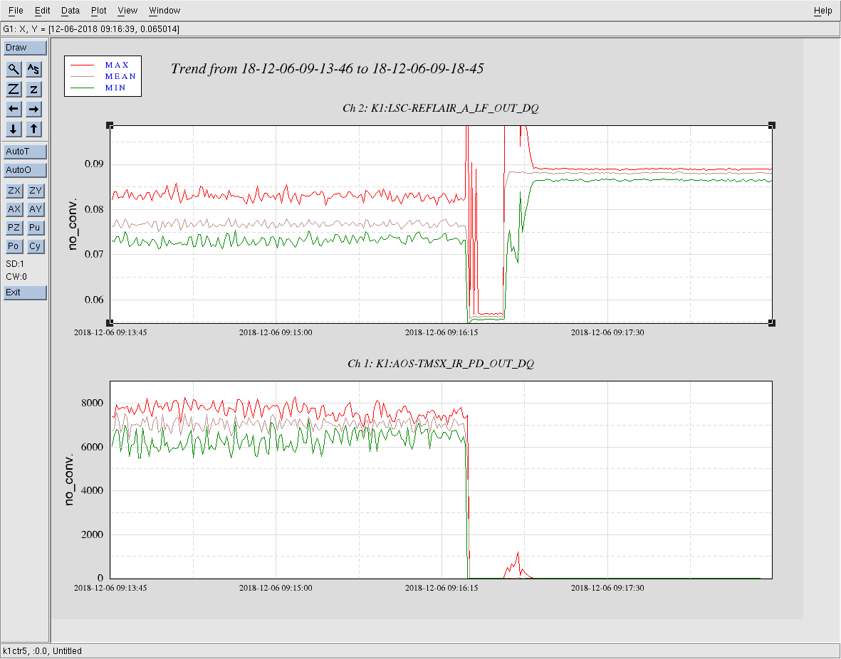
2. Loss measurement (reflectivity of X arm when locked)
We measured the power of light the REFL PD recieved when X arm was locked and when ETMX was misaligned.
Comparing them we will have (roundtrip loss + TETM) * (the ratio of TEM00 carrier field) (See LIGO-G1501547, for example).

= Direct Catch of X Arm Resonance =
We tried to directly lock the main laser frequency to X arm without using ALS, and succeeded.
The procedure to directly lock it we established is the following:
0. prepare CARM servo like this.
IN1 gain: 26 dB
IN1 disabled
No common boosts enabled
Fast gain: 12 dB
Fast enabled:
"MCL" filter in LSC-MCL turned on, and set LSC-MCL_GAIN to be 1.2
1. enable IN1.
2. wait a few seconds for X arm being locked.
3. enable two common boosts
4. enable "boost" in LSC-MCL

Note:
* changed the f1 frequency from 18.88 MHz to16.87515 MHz
* Before the last trial of the cavity scan, we set the FG output for f1 from 10dBm to 15dBm, and forgot to set this back to 10dBm
* At the end of the day, we checked the IR beam spot position on each test mass, and found that the spot on ETMX looks too low. We have to repeat the measurements with good beam spots

Images attached to this report
Comments to this report:
yutaro.enomoto - 0:26 Friday 07 December 2018 (7291) Print this report

= Loss measurement from cavity reflectivity =

The power of reflection when locked: Plock = P0 (1 - M * 4TITM/Ttot2 * (Tloss+TETM)),
The power of reflection when ETM is misaligned: Pmis = P0 (1-TITM),
where M is the ratio of the power of carrier TEM00 light that matches to the cavity mode.

From the cavity scan measurement, M ~ 0.95 (with a few parcent error). And from the reflectivity measurement, Plock/Pmis = 0.6440(6).
Note that we normalized the power at REFLAIR_A by IMC_CAV_TRANS_OUT, so that the power fluctuation at input optics can be negligible.
So the roundtrip loss Tloss can be calculated to be
Tloss = 410 +/-10 ppm.
The error comes from rough estimation of M, which will be updated by the detailed analysis of the cavity scan.

Discussion - clipping loss?
According to this document by Kiwamu (senario1), miscentering on a test mass by 4-5 cm will result in the roundtrip loss of hundreds of  ppm.
Looking at the picture on ETMX, there might be miscentering by 4-5 cm, which can explain high loss and the fact that the losses we got yesterday and today did not match.
We have to redo the measurement after we confirm that the beam spot on each mirror is well centered.

kiwamu.izumi - 9:55 Friday 07 December 2018 (7292) Print this report

The direct catch of the IR laser frequency --- a fantastic progress.

shinji.miyoki - 12:06 Friday 07 December 2018 (7293) Print this report
me too! The longest FP storage time ?
eiichi.hirose - 12:11 Friday 07 December 2018 (7294) Print this report
Thank you Enomoto-kun et al for the interesting reports. Here, I would like to review what MIR estimated in the past. The total loss of the KAGRA FP cavities would be 50ppm (for instance, JGW-T1809173-v1) based on both an optical simulation with the real figure maps and results of coating characterization. The breakdown of the estimated total loss is as follows. 50ppm = 10ppm(due to figure error) + 40ppm (due to the others such as scattering, absorption). aLIGO experienced some discrepancy ~20-30ppm in the total loss between what was measured in the detectors and what was predicted. So, even with some unknown loss sources we did not take into account in the estimation, we really hope the total loss with a better beam spot condition will be less than 100ppm, which is still 50ppm greater than our prediction. Looking forward to the result with a better spot condition.
yuki.miyazaki - 21:56 Friday 07 December 2018 (7301) Print this report
[ Enomoto, Miyazaki]

We did cavity scan measurement yesterday. Keeping Xarm locked to Green, we shifted the offset of frequency-locking between IR and Green, then got some resonant peaks.
The measurements was carried out twice. Before the second measurement we increased the modulation depth of f1: 10dB --> 15dB.

##Information
Sweep Speed: 100 Hz/s
modulation frequency f1 = 16.875150 MHz
modulation frequency f2 = 45.000400 MHz
FSR = c/(2*3km) ~ 49.965 kHz
round trip Gouy phase separation ~ 4.376 rad (<=> ~34.80 kHz)

We identified some peaks as following way of consideration:
1. A higher mode appear at 34.8kHz after a lower mode.
2. (f1 = 337FSR + 36.807kHz.) Sideband peaks of f1 appear 36.8kHz (or 13.2kHz) distant from 00-peaks.
3. (f2 = 900FSR + 31.531kHz.) Sideband peaks of f2 appear 31.5kHz (or 17.5kHz) distant from 00-peaks.
4. We took a movie of beam shape during the measurement. So unknown peaks may be identified using it. (But not yet checked it.)

From this result you can obtain cavity properties:
1. Finesse, from fitting with Lorentzian. (Not yet tried)
2. Arm length, by FSR
3. Gouy phase


##Arm length
We obtained FSR by using sideband peaks and it was 49.96554(4) kHz.
(Of course you can find FSR by measuring the distance between 00-peaks and it was 49.95(5) kHz, which has more errors.)
Therefore the Xarm length was calculated as 2999.992(3) m.

##Gouy phase
round-trip Gouy phase is given as (Gouy = 2*arccos(sqrt(g_front*g_end)), g=1-armlength/RoC).
Measured round-trip Gouy phase = 4.37570(1) rad.
Images attached to this comment
yutaro.enomoto - 22:08 Friday 07 December 2018 (7303) Print this report

> Miyoki-san
Yes, we had the logest storage time so far. That is ~ 20 mins. This lock was intentionally terminated.

> Hirose-san
Thank you for the comment.
We will re-do the same measurement procedure with a better spot as soon as possible.

shinji.miyoki - 23:09 Saturday 08 December 2018 (7306) Print this report
2999.992(3) m. -> Amazingly precise !
yutaro.enomoto - 23:28 Tuesday 11 December 2018 (7332) Print this report

== Comprehensive analysis of the cavity scan held on the last Thursday ==

Here I report the results from the automatic peak finding and fitting of them for the cavity scan we did the other day.
From the fitting results and some mathematics, the cavity length, transverse mode spacing, and roundtrip Gouy phase are obtained:

L = 2999.990(2) [m]  <=> FSR = 49.96557(4) [kHz]
TMS = 34.79(5) [kHz]
ζGouy = 4.375(5) [rad] = 250.7(3) [deg]

Here I put the two plots, one of which shows the fitting results of the cavity scan and the other of which shows the fitting for the transverse mode spacing.
Note that the error for TMS is evaluated from the systematic error you can see in the bottom plot showing the residual error. 

I also attach the code I used.

= Some notes =
* On radii of curvature of ITMX/ETMX.
According to Hirose-san's report, R_ETMX = 1907.83 +/- 2.14 [m], R_ITMX = 1904.54 +/- 2.08 [m].
From these numbers, TMS should be
TMSfrom RoC = 34.703(24) [kHz].
This is not consistent with the value obtained from the cavity scan.
Note that TMS value obtained from the cavity scan we did on Saturday gave us almost the same number, 34.78(5) [kHz]
There is some discrepancy between the measured Gouy phase and that expected from the characterization of the coated test mass. Why???
This dicrepancy corresponds to ~ 5-10 [m] change of the radii of curvature.

Images attached to this comment
Non-image files attached to this comment
Search Help
×

Warning

×