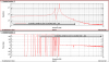
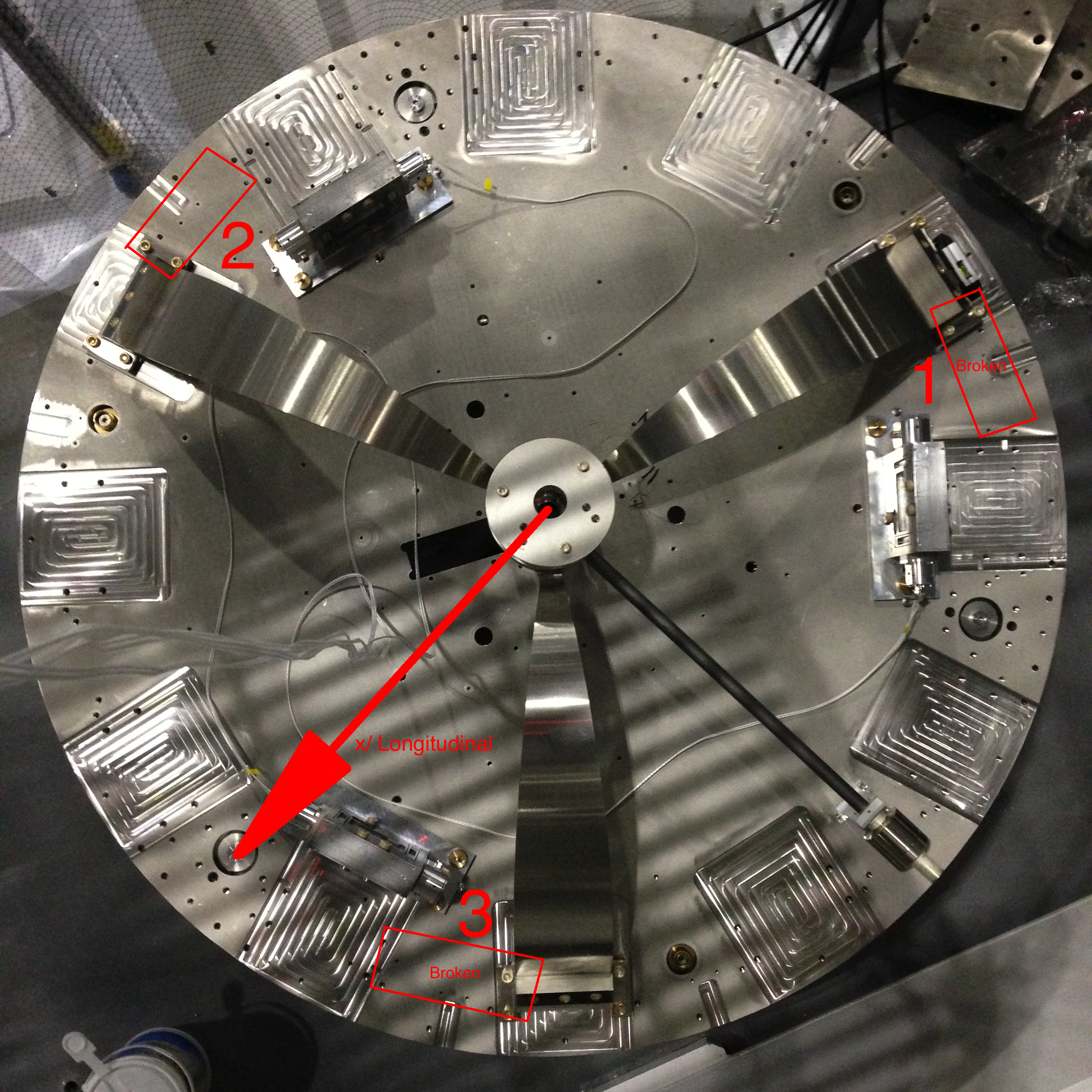
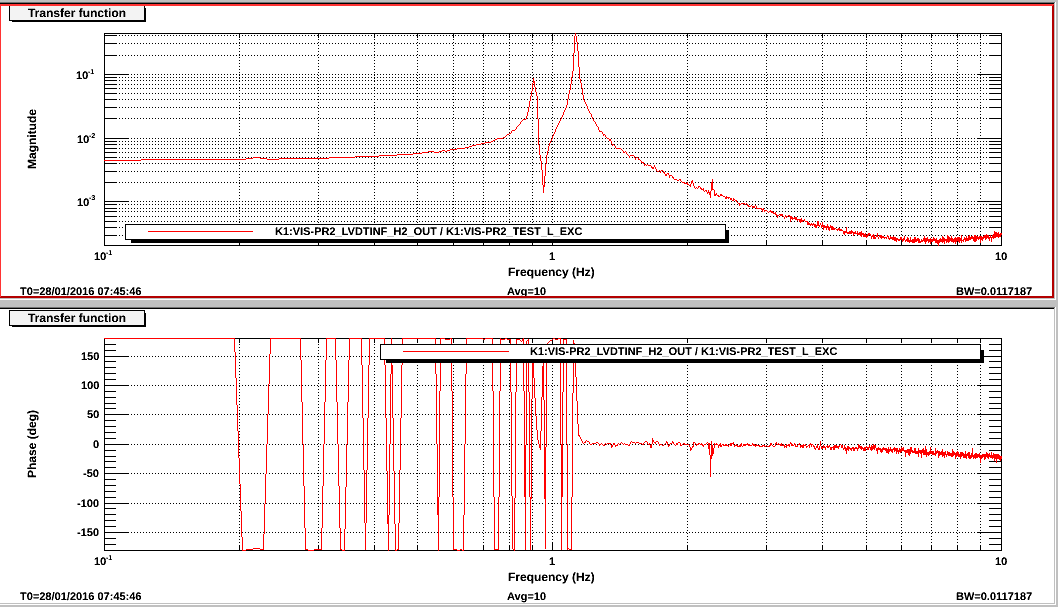
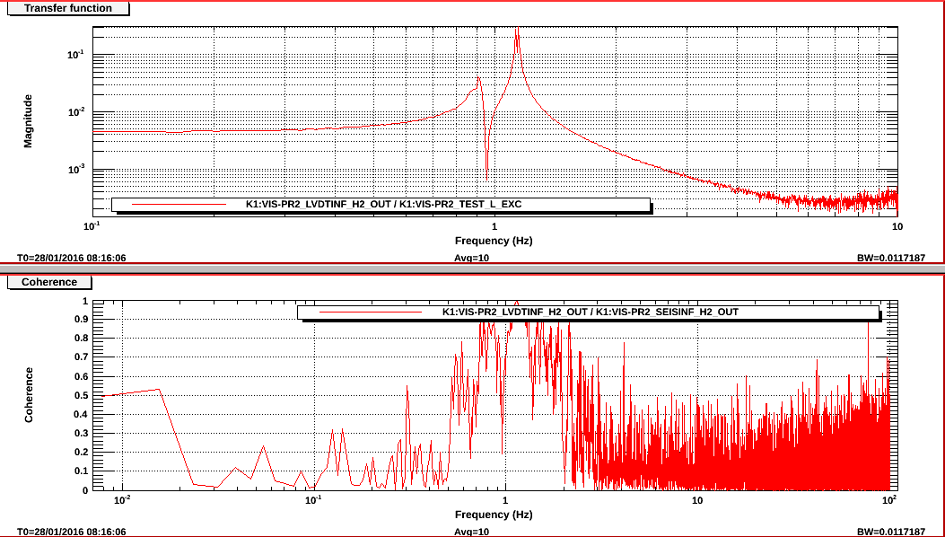
Because the unloaded IP stage is very stiff (1Hz in stead of the normal sub-100mHz tuning), I first tried to put as much noise in the L_test (using a geometric guess for the actuation matrix) to move the IP roughly in the x/ L direction; see results and time signals in highstrenghtactftf.png and ftchighstrength.png, respectively. Noise was injected DC-10Hz, amplitude 200000 in diaggui. We see the L_Test and LVDT_H2 being out of phase (low freq phase = +180 deg), so I guess that means that LVDT_H2 polarity is switched or the simple geometric actuation matrix is not good, i.e. one of the ACTs has opposite sign. Well, we already see that it's not good as we see two modes here, the mode in x/ L at ~1.16 Hz and yaw mode at ~910mHz. The x/ L mode seems not degenerate, so that would mean the IP flexures are quite symmetric. The ACCs were all bouncing in the frame, so the excitation was just too large to get any data from the ACCs; especially ACC 2 and 3 have own natural frequency very close to the modes of the unloaded IP at this point (in the future this won't be a problem, as both L and Y mode will be in the 50-200 mHz region)
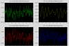
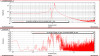
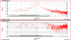
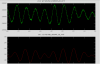
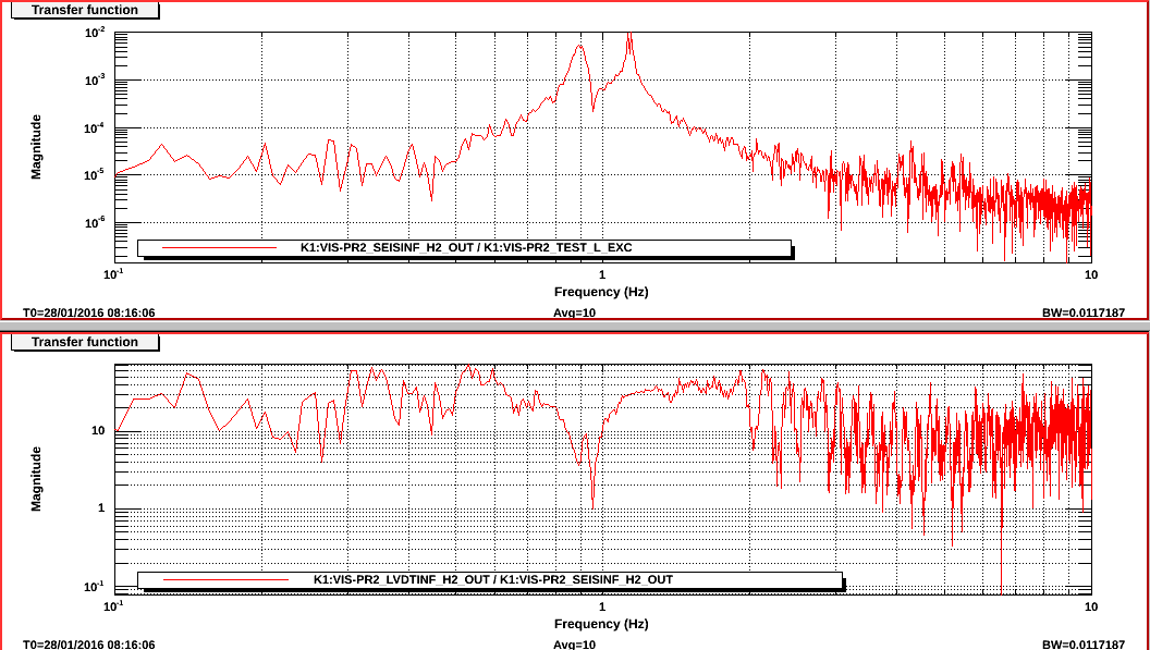
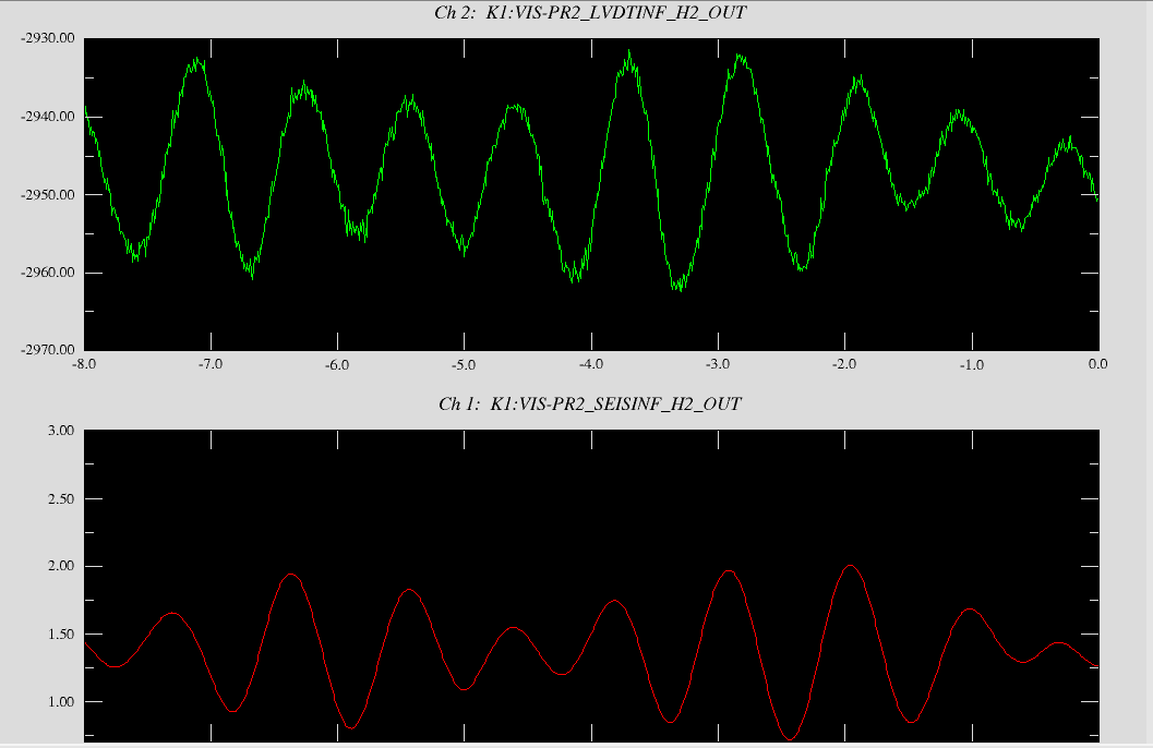
Wanting to get the ACCs (no calibration applied yet, just raw voltage signal now) to measure something as well, I did another measurement with lower excitation: DC-10Hz, amplitude 20000 in diaggui. See the results of LVDT and ACC and time series of them in ftclvdt.png, ftcacc.png and ftctime.png respectively.
- I see a similar transfer function, but now with a tiny degeneracy in the (maybe x/L and y/T mode) splitting the ~1.16 Hz peak.
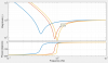
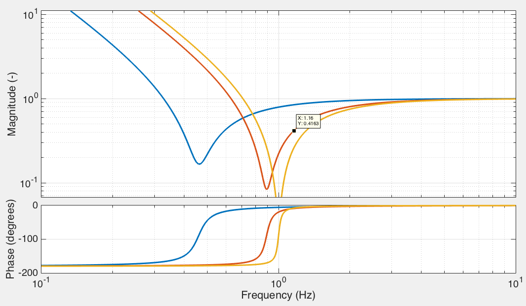
- The ACC TF also looks expected: proportional to f^2 below the resonance, which will become flat after multiplying with the calibration, shown in acc2calibrationnoVpermmyet.png. and proportional to 1/f^2 above resonance. From 30Hz onwards, the signal becomes noisy, but we shouldn't forget that the mass is hanging in open air, i.e. air currents (flow box!) and acoustics presumable couple in quite badly.
- LVDT and ACC show high coherence around the resonance and lower around it on both sides, probably because of the air current/ acoustic spoiling of the ACC performance
- Just at/ around the resonance, where coherence is one, I calculated a very crude V/mm for the ACC2 LVDT (still have to perform tilt calibrations for all 3). At that frequency, it's not flat to displacement yet (see
acc2calibrationnoVpermmyet.png), so the ~30 mum/V coming out the LVDT/ACC TF (see lower panel lvdtacc.png) has to be multiplied by 0.4. This gives 12 mum/V or 83.3 V/mm, which is perfectly reasonable when comparing it to Alessandro's earlier calibrations (posted ~2 weeks ago). The LVDT board settings were such that its exciting 10 kHz was of smaller amplitude (30% or so), but the gain trimmer was at 20 Ohm in stead of 35 Ohm, so we actually expect a slightly higher V/mm
-------
Conclusions
- During fixing the LVDTs, we should perform the tilt calibrations to get the V/mm figures for all 3 ACCs (comparing to ~83.3 V/mm for ACC2 as they all should be roughly the same)
- With calibrated ACCs we could try, once the IP is loaded with tuning masses, set up a damping loop. This would imply using the ACCs to diagonalise which might not work as you have to diagagonalize with ~30 mHz sines
- We should fabricate boxes to put around the ACCs if we want to perform a proper test in air
