At the cables at the rack coming from the IP stage, I measured the following resistances:
numbers mean: LVDT in [Ohm] LVDT out [Ohm] ACT [Ohm]
F0 H1 OL 252 148
F0 H2 451 248 146
F0 H3 OL 247 148
The day before yesterday, Fujii-kun and me (team Shimeji), attempted a repair for both.
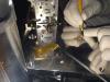
At LVDT_H1 we saw a broken end and assumed they came of the connector. However, at the connector, all still looked fine. So we stripped the wire with a small knife (see bsipwirestripping.jpg | on a small plate not to make the stage dirty) and tried to see if we could find a resistance over this end and one pin of 1-6 of the DSUB9. We found 217 Ohm over end-pin6, so soldered the end into pin 1. Assuming it was repaired, that was the end of our works on LVDT_H1.
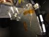
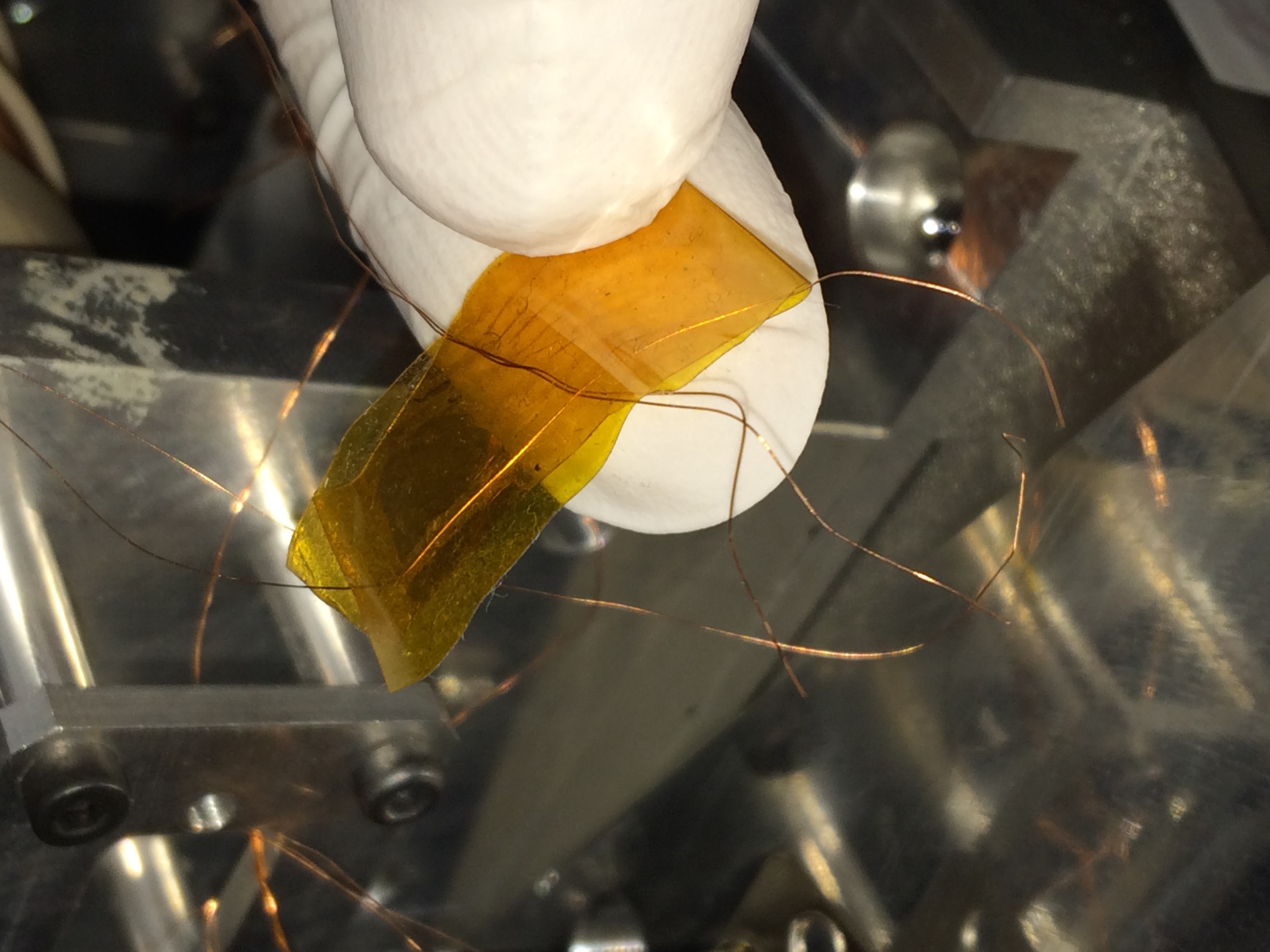
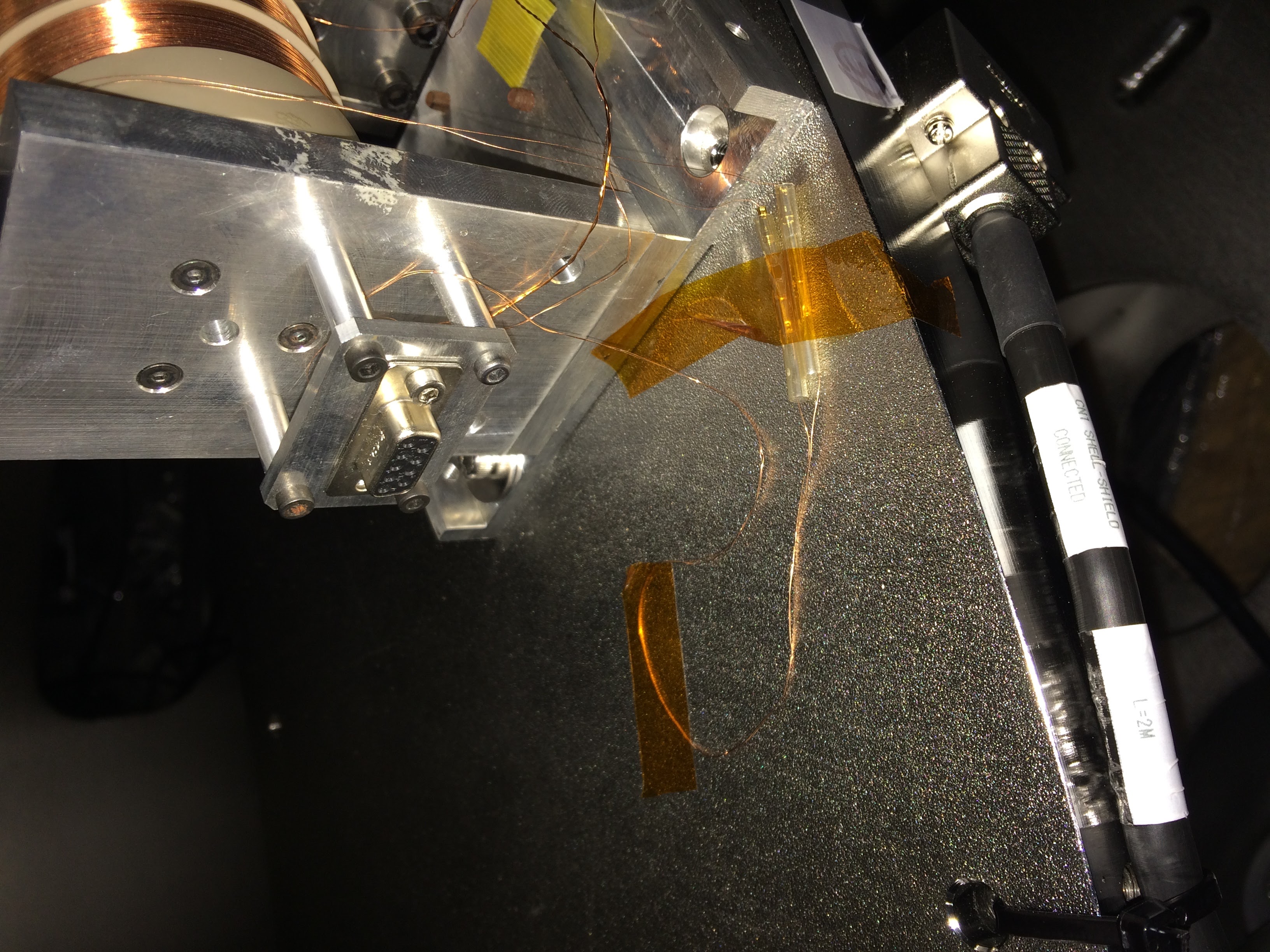
At LVDT_H3 we saw taped 4 ends (see bsiplvdt34ends.jpg) and tried to figure out, assuming 2 came from the connector side and 2 came from the coil, which was what by beeping and resistance measurements. After establishing which was which, we crimped connectors to all 4 ends and connected them (the wires from coil-side were too short to solder directly into connector | see bsiplvdt3fixed.jpg). After this "fix" we measured ~450 Ohm at the the 1-6 of the connector, we appreciated the discrepancy between LVDT_H1 and LVDT_H3 secondary coil resistance, but the day was ending, so we left the clean area.
After the "repair", the cables at the rack coming from the IP stage, I measured the following
F0 H1 217 252 148
F0 H2 451 248 146
F0 H3 450 247 148
Takanori has, in his prototype test, measured the following:
F0 H1 453 252 148
F0 H2 451 248 146
F0 H3 451 247 148
The discrepancy in the LVDT in coil of LVDT_H11 is the most striking; my theory is that the end that I found is not the end of the coil (cables from connector still looked to go to the coils) but the coil took a hit and the end that I had came off roughly halfway in the coil, hence the roughly half resistance to expected. LVDT_H3 looks okay and, before trying to work with the LVDTs, it was assumed this was properly repaired.
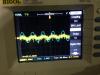
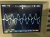
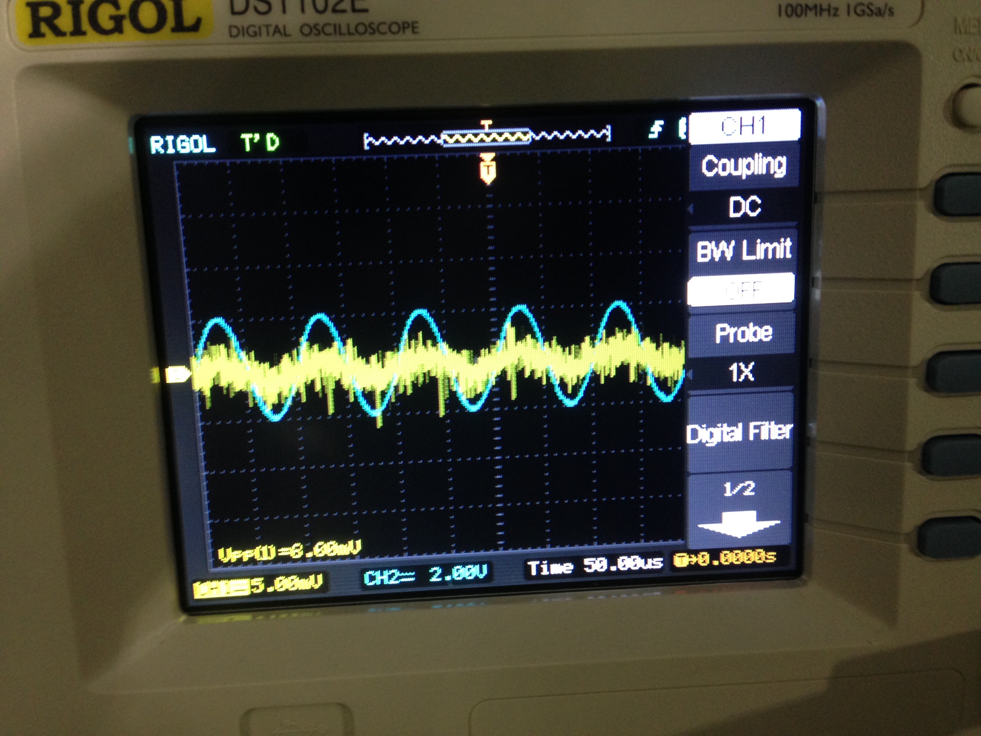
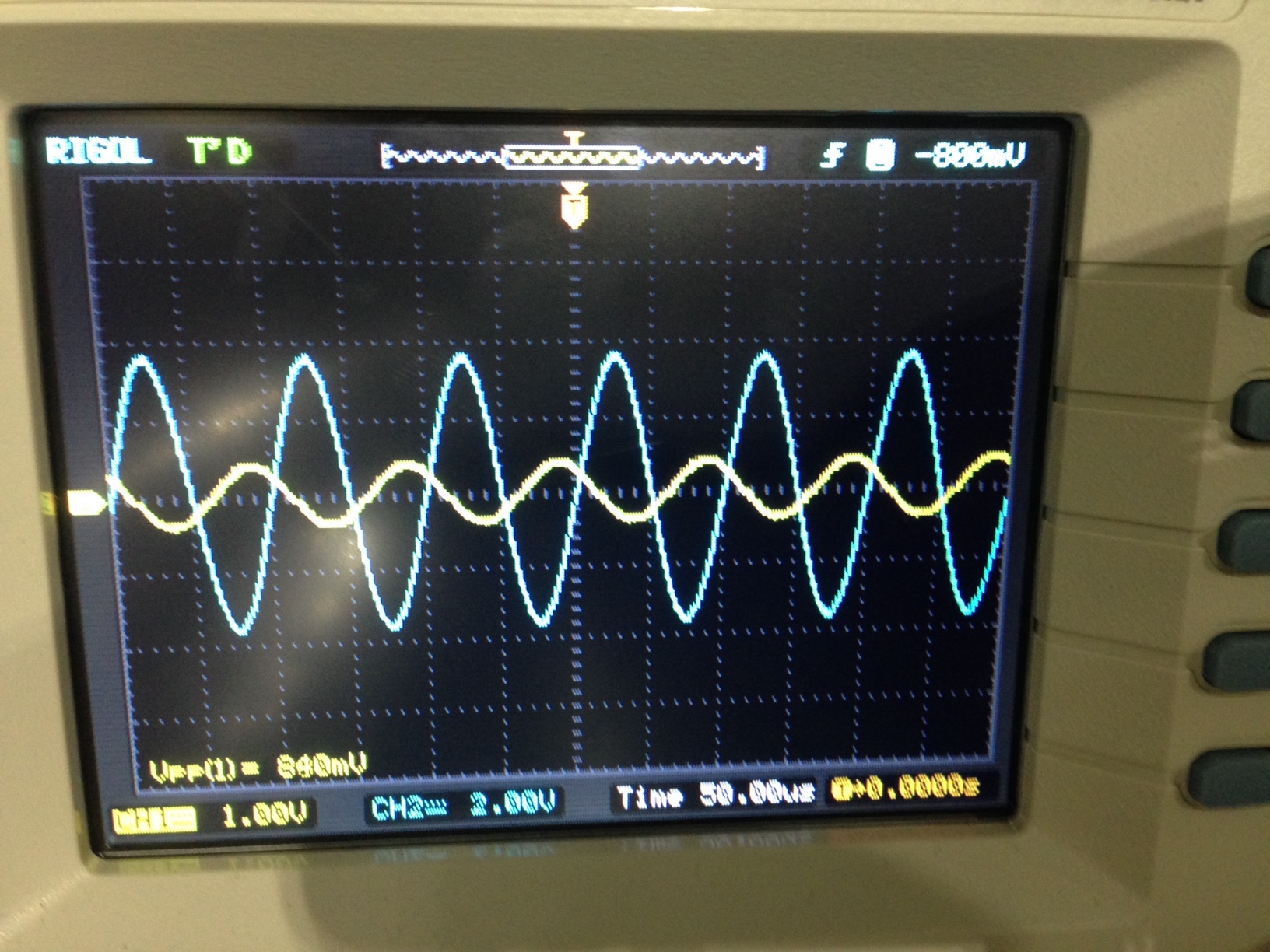
When cabling the LVDTs to the boards and to the digital system, looking at the 10 kHz signals going (taken from signal generator) to and coming back (taken at G1,2,3 probe point on the board, see my LVDT manual posted ~2 weeks ago on K-log) from LVDT_H1 and LVDT_H3, they didn't look good (see LVDTrefAndReturnSignalBad.jpg). I see a bit of 10 kHz coming through, but this could well be some electric coupling between wires at the connector, i.e. crosstalk. The LVDT_H2 signals looked good (see LVDTrefAndReturnSignalGood.jpg)
------
Conclusion:
LVDT_H1 1-6 coil is broken, probably halved -> needs replacement
LVDT_H2 works
LVDT_H3 1-6 coil shows the proper resistance, but still, the LVDT doesn't seem to work.
NB It's quite a mystery to me why it doesn't work, despite me seeing the correct resistance. Flipping the ends with respect to earlier configuration would only flip the polarity (this is my understanding of the LVDT operations) I can't think of any case where I do see the proper resistance (almost exactly matching Takanori's measurement half a year ago) and the LVDT doesn't work.
