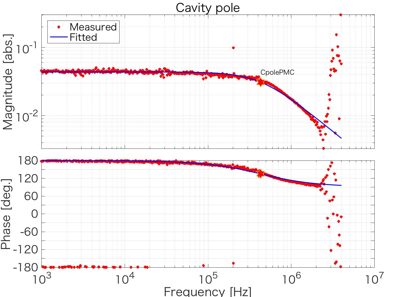
The cavity pole of the PMC was measured by measuring the AM TF of the PMC. The estimated cavity pole is
427(7) kHz,
which corresponds to the finesse of
173(3).
The designed value is 600 kHz and 124 respectively. Also, the cavity pole estimated in another measurement was 690(70). So they are not consistent with the designed value
The measurement detail is as follows.
1. Measured the TF from the AOM driver input to the power fluctuation before the PMC
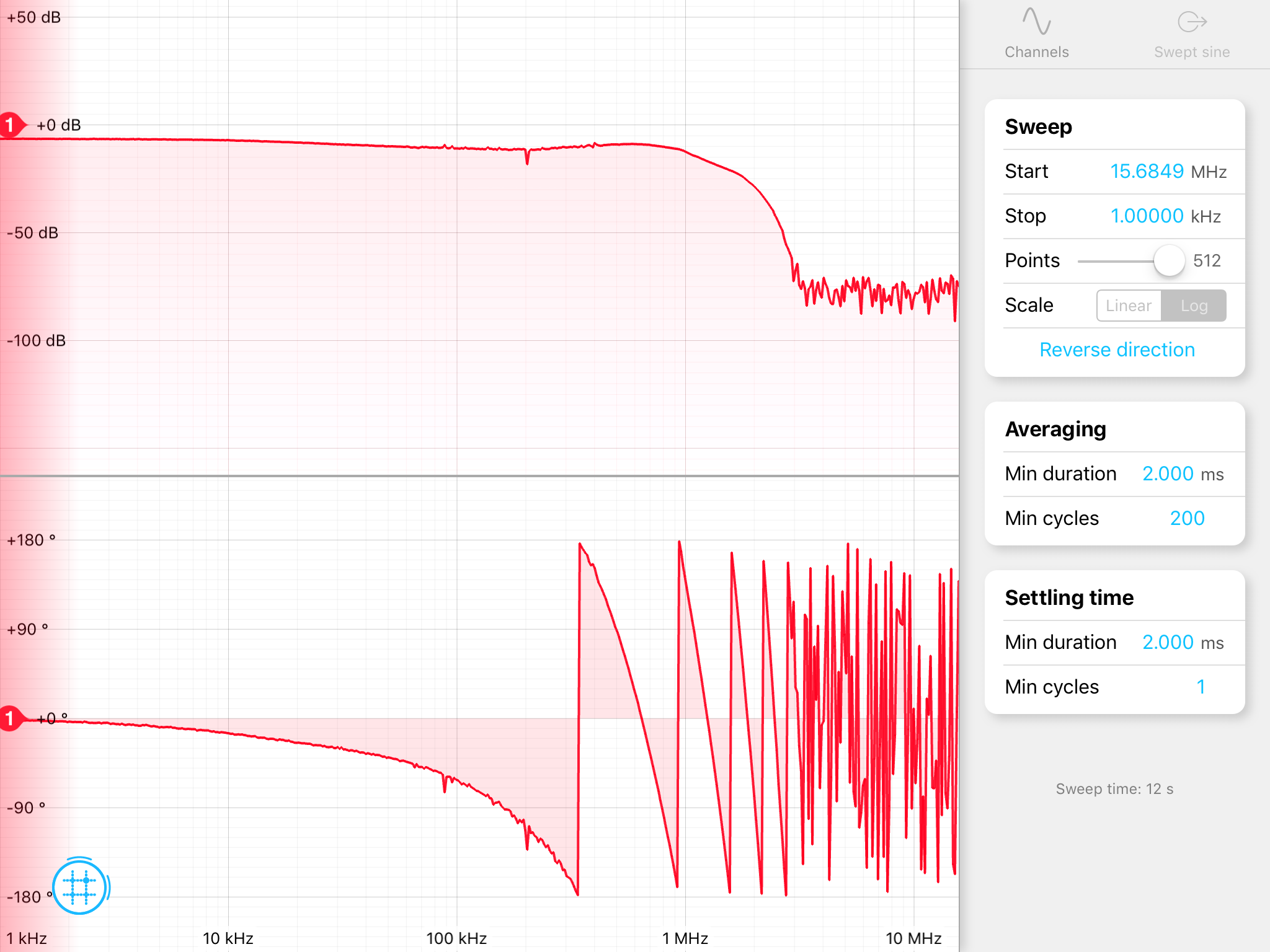
To know the actuator response of the AOM, and the sensing response of the PD, the TF from the AOM driver input to the PD output was measured. I put the pick-off mirror just after the AOM and that beam was injected into the PD (PDA100A2). The measured TF is shown in FIg.1.
Fig.1 TF of the AOM and the PD. It's used for the calibration of TF measured in measurement 2.
2. Measured the TF of the AM
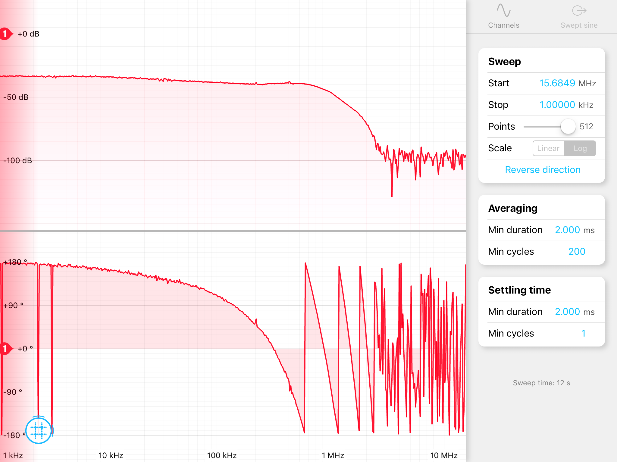
The PD used in 1. measurement was moved to the PMC TRANS and the TF from the AOM driver to the PD output was measured. The measured TF is shown in Fig.2.
Fig.2 TF of the AOM, the PD, and the PMC.
3. Calibration and fitting
We can get the response of the AM through the PMC by dividing the TF measured at the TRANS by the TF measured before the PMC. The divided TF and the fitted curve are shown in Fig.3.
Fig.3 Calculated TF of the PMC and the fitted curve.


