Finally, I succeeded to close the temperature loop of the PMC.
(I reported that I could close, but it was not true.)
--------------------
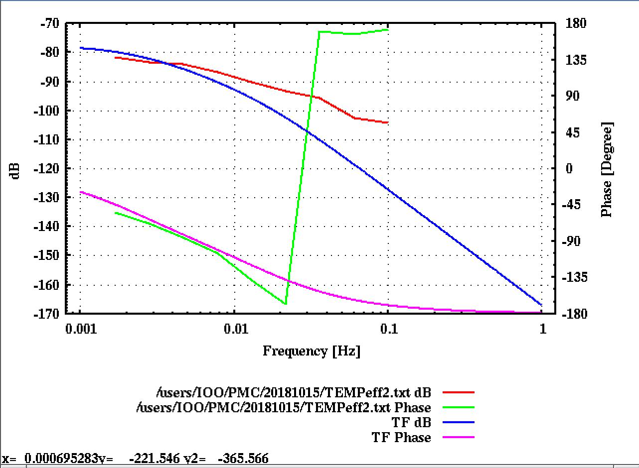
1. Transfer function measurement of the heater.
I feel it is not a good idea to design the loop with try-and-error from scratch. Therefore, I decided to measure the transfer function of the heater and design it, although this measurement takes long like a day. The excitation signal was injected in the heater and measured the transfer function from the heater signal input to the error signal of the temperature loop which is the control signal of the PZT slow loop. The measured transfer function is shown in Fig1. I fitted by using liso script. There seem to be two thermal poles below 0.01 Hz and the loop cannot be closed properly due to the phase delay of these poles.

Fig.1 Measured TF of the heater (red: gain, green: phase) and the fitted curve (blue: gain, purple: phase)
The actuator efficiency of the heater can be estimated as
(DC gain of TF [V/counts] ) * (PZT actuator efficiency [Hz/V] ) = 1e-4 V/counts 922 kHz/V ~ 90 Hz/counts
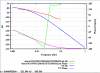
2. Design the servo filter.
The designed OLG is shown in Fig.2. The basic design is the simple integrator, and I put an additional zero at 0.003 Hz to compensate the thermal pole.
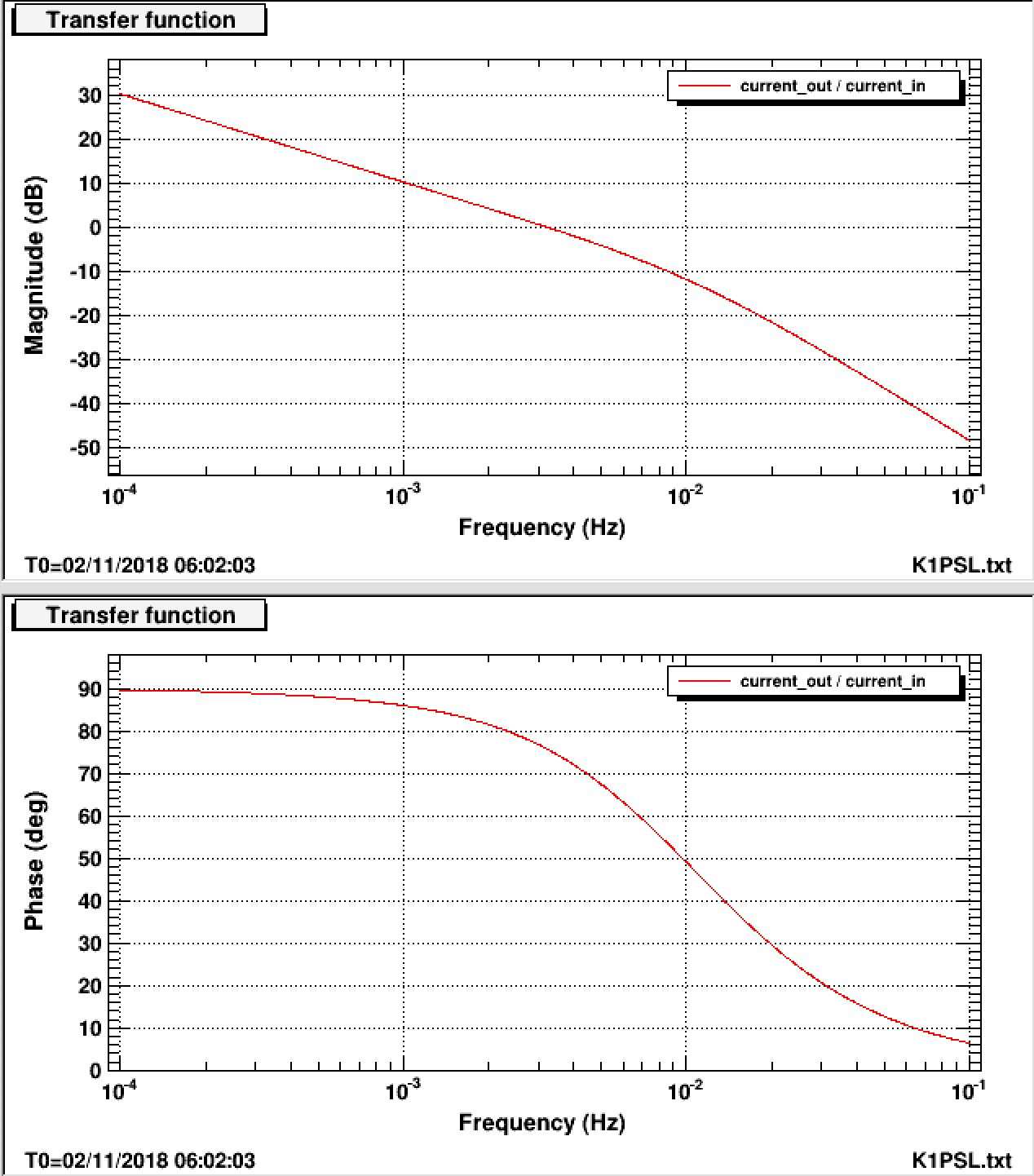
Fig. 2 Designed OLG. The fitted heater TF is used as the actuator response.
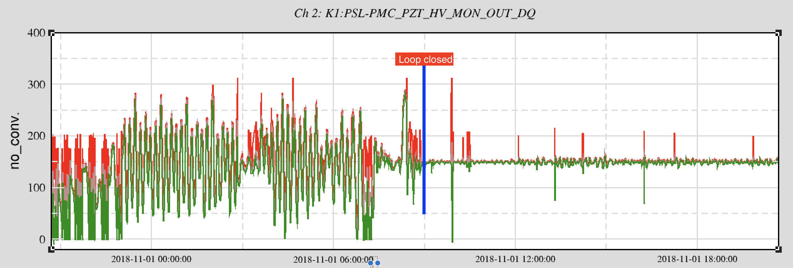
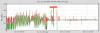
3. Time series of the PZT control signal.
The time series data is of the PZT control signal and TRANS signal of the PMC is shown in Fig.3. The temperature loop is turned on at the center of the plot. The DC of the PZT control signal is properly suppressed.
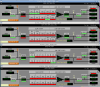
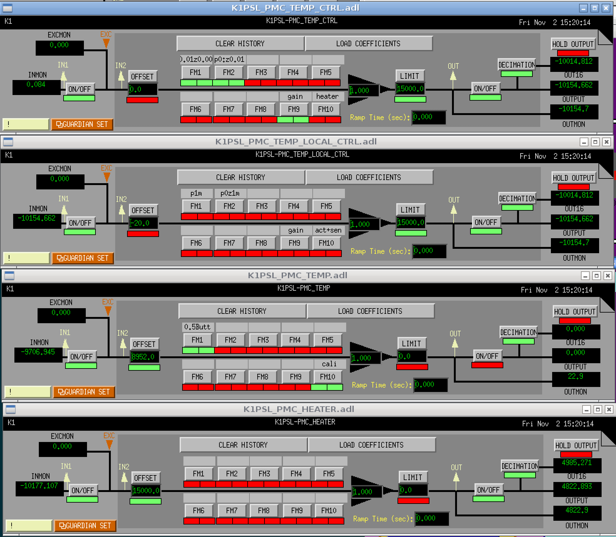
4. FB settings
The related FB settings are shown in the attached figure.
-----------------------------
Notice
I put 15000 counts offset at the output port to set the operating point at the center of the DAC range. With regard to this, we need to notice that it takes a couple of hours to reach the equilibrium. We will need to wait after we turn the k1psl model off for a long time.