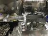
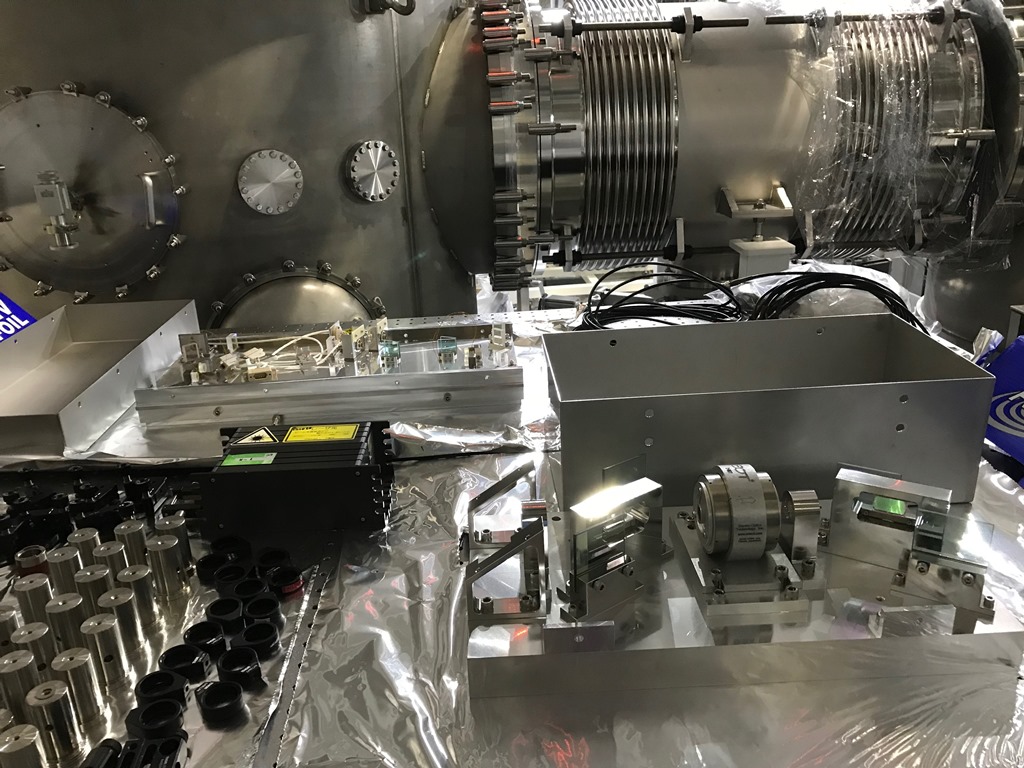
On the 11th, the OMC, OFI, and some optics for the installation were delivered safely from Tokyo Tech.
Find them below in the first picture.
On the 12th, we set up cables for the DCPDs and QPDs. The PZT cable will be attached on its delivery
scheduled next week. One of the cables may have to be tied on the side or on the bottom as it might
go too close to the frame.
S.Otabe, H.Sasaki, and K.Somiya
On Oct 15, we assembled the blade spring bases on the OMC frame. We also tried to test the strength of the wire clamps
and it turned out the head of screws on the lower clamp touches the lower clamp mount.
Another work on the 15th is the setup of the laser system for the OMC installation. The input optics is covered by an
enclosure and the output power is lower than 2mW.
On Oct 16, Mirapro people joined the installation work. First we, with Ohishi-san, measured the actual height of the
optical tables to find that the height of the OMC table is 10mm higher and the height of the OMM table is 7mm higher
than the design. The Mirapro people adjusted the height by tuning the support bolts and leveled the table properly.
Second, we moved the OMC frame from the AS table to the chamber. This was a practice of the installation of the OMC
frame with the suspended OMC which is planned this Thursday.
At last, Yamada-san from Mirapro replaced 3 blank flanges on the OMM/OMC chambers by feed-through flanges. One on
the OMM is used for OMMT2 (5 ports). Two on the OMC is used for OMMT1/OSTM (10 ports) and OMC (4 ports). There are
2 free ports saved for picomotors in one of the two flanges, which is not yet tightly screwed.
K.Somiya, K.Kusayanagi, S.Otabe, and H.Sasaki
- PZT cables connected via crimp contacts
- Lower clamp of the OMC suspension assembled
- On-board wiring done
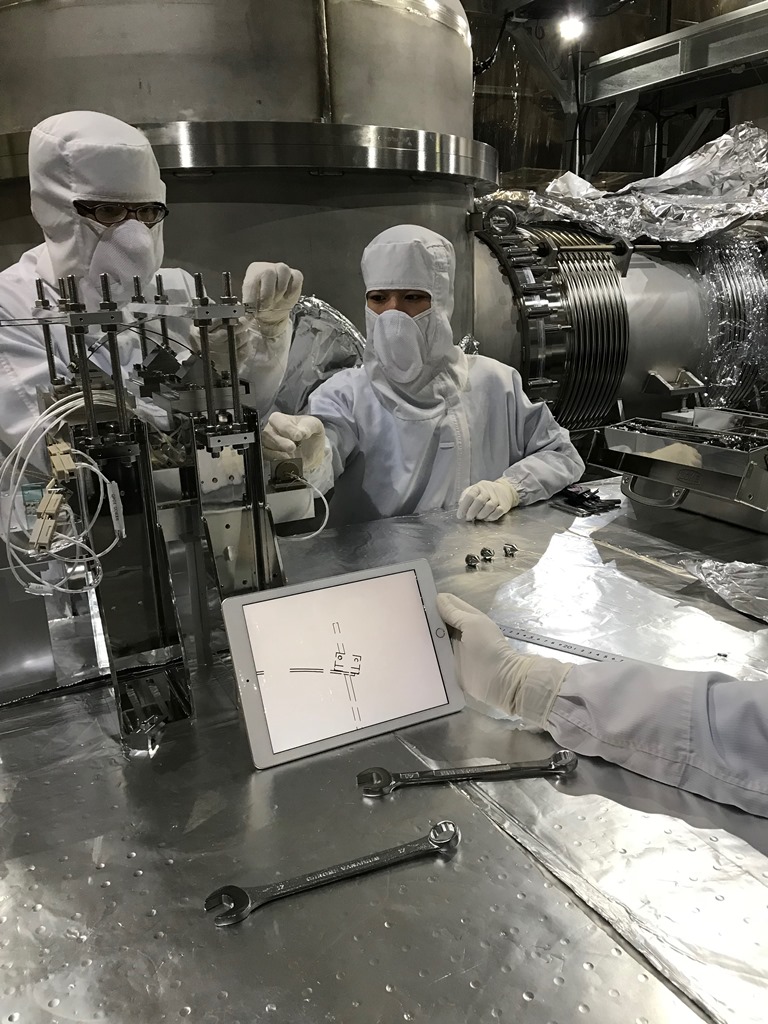
- OMC breadboard placed on pillars underneath the OMC frame
We then started tuning the relative location of the OMC breadboard to the OMC frame
using a small mass suspended from the upper clamp of the suspension. This is still
on-going.
Somiya, Sasaki, Otabe, Kusayanagi

(1) Refined the relative location of the OMC breadboard to the OMC frame.
(2) Released the support bar so that we can relocate the suspension bases.
(3) Relocated each base so that the suspension hole is about 48mm away in the direction of the blade spring projected to the breadboard.
(4) Bent the blade in a proper height to check the suspension hole is under the upper clamp on the blade spring.
(5) Lowered the support bar so that the top of the blade is about 207mm above the breadboard.
(6) Clamped a stainless wire on the upper clamp with holding the OMC breadboard.
(7) Added some counter masses.
(8) Released the OMC breadboard.
Up to this point, if the OMC breadboard were at a proper height, the suspension process would have been finished.
The breadboard height was, however, about 25mm higher than the designed value.
Comparing the actual distance and the designed distance of each stage, we found that (i) the suspension wire was about 11mm
shorter and (ii) the blade seemed to bend less. So we did the followings.
(9) Flipped the upper clamp so that the suspension point can be lowered.
(10) Replaced the wire and tried to make the most use of the 300mm wire (it would have been easier if the wire were longer).
(11) Added more weight so that the four corners of the breadboard are all 195mm from the floor.
The work was successful. The original values were
- suspension wire length (end of the upper clamp to breadboard): 222.5mm
- height of the bottom of the upper clamp from the top of the frame: 102mm
And the final values were
- suspension wire length (end of the upper clamp to breadboard): 230mm
- height of the bottom of the upper clamp from the top of the frame: 109.5mm.
As the differences of these two values is same, the beam height is same.

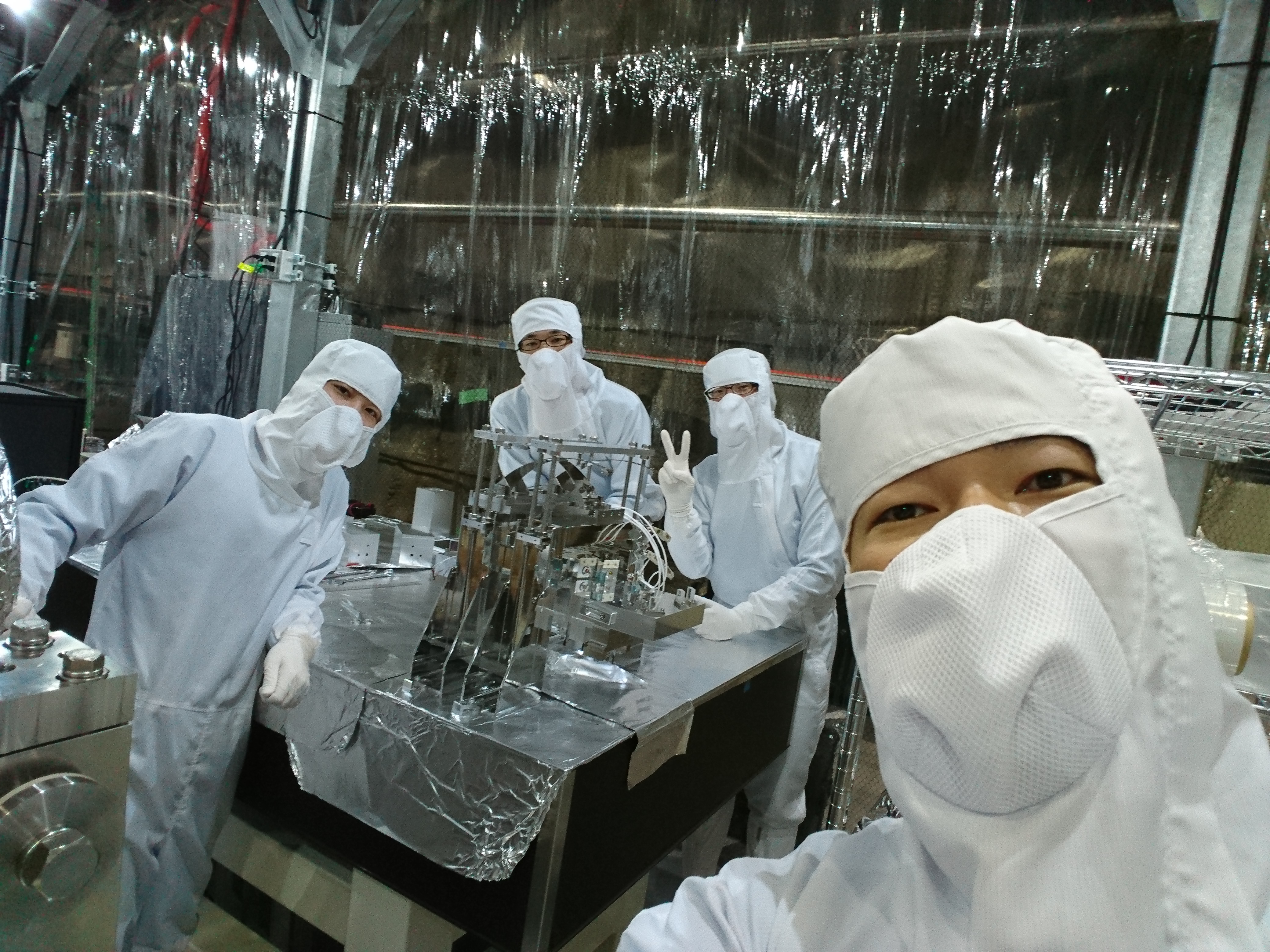
With Ito-san and Yamada-san from Mirapro, we successfully installed the suspended OMC into the OMC chamber.
The most of the in-vac cables were then connected to the feedthroughs.
We then located four magnets underneath the OMC breadboard. The motion seemed to be damped well.
We also installed 2-inch mirrors for the alignment work scheduled next week.
The original plan was to put three mirrors in the position of OMMT1/2/OSTM but we found that the
duct between OMM and OMT chambers have not been connected so the test will be performed inside
the OMC chamber using two steering mirrors.
K.Kusayanagi, S.Otabe, H.Sasaki, and K.Somiya
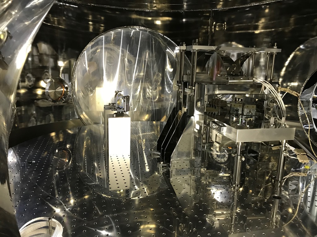
Otabe-kun did mode-matching of the OMC laser and took alignment to the OMC
using a pair of 2-inch steering mirrors in the chamber. We then started to
manufacture some adapters to connect our oscilloscope/oscillator to the DB9
feed-through connectors so that we can use PZTs/PDs/QPDs for fine alignment.
S.Otabe, K.Somiya
We connected the OMC PD/QPD signals to an oscilloscope and the PZT input to an oscillator via feed-through.
We have not seen a PD signal yet but the PZT worked properly.
We put the Preamp circuit into the Preamp chamber to certify the size of the circuit and it fit well.
We also did some work on the digital system: see klog 6682.
Somiya, Otabe, Nakashima
We found a couple of things for what we did the previous day.
(i) We assigned CH0-15 of the OMC DAC but CH4-15 were for the OMMT and the OMC/OMMT models conflicted.
Yamamoto-kun found this and he fixed the problem for us (thanks!).
(ii) The DCPD output was not connected to DCPD as we did not have the preamp yet.
This is probably why we did not even see noise from the DCPD output while we did from the QPD.
On the 24th we started making DCPD driver circuit. Receiving two chassis and regulators from AEL,
we assembled the DCPD driver with a pair of TVS circuits made by Nakashima-kun (see JGW-D1809199-v3).
The other chassis is for the QPD driver (see JGW-D1809198-v3), for which we are still waiting for a
circuit board from a company.
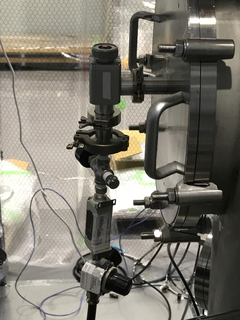
On the 25th we finished soldering cables for the DCPD preamp and brought the preamp and the driver
to the tunnel. We then assembled the in-vacuum DCPD preamp (see the attached photo). It turned out
that the Dsub 9Pin gender was wrong in various places. We re-soldered the connectors for the preamp.
We decided to use gender-changers for the driver.
somiya, otabe, nakashima
We connected the DCPDs and PZTs of the OMC to the digital system and saw the cavity resonance in the transmisssion with sweeping one of the PZTs. After we left the mine, however, we realized that the DCPD driver power supply was off. It means there is no bias and no amplification of the photo current.
We asked Nakamura-san in Mirapro to let us use a valve that connects a clean air nozzle to one of the OMC chamber flanges. The clean air was connected to the OMMT chamber. We disconnected the nozzle and connected it to the OMC chamber.
somiya, otabe, nakashima
On Oct 29 we found that the pin assignment of the preamp was right side left.
We fixed the problem and re-installed the preamp on the 30th, but we found that
an ope-amp AD8672 in one of the DCPDs had gone bad.
On Oct 30 we also found that the pin assignment of the preamp cable was wrong
and the shield potential was +5V. Please find below the updated wiring diagram.
https://gwdoc.icrr.u-tokyo.ac.jp/DocDB/0091/T1809176/006/Chart6.pdf
(We still need to consider flipping the PD/QPD in-air cables.)
arai, otabe, nakashima, somiya
We asked Kamiizumi-san to replace the broken op-amp on the DCPD preamp,
and Kamiizumi-san and Shimode-san fixed it for us by the end of the day (thanks!).
We checked if the other preamp works fine by adding a signal from an oscillator
and it was successful.
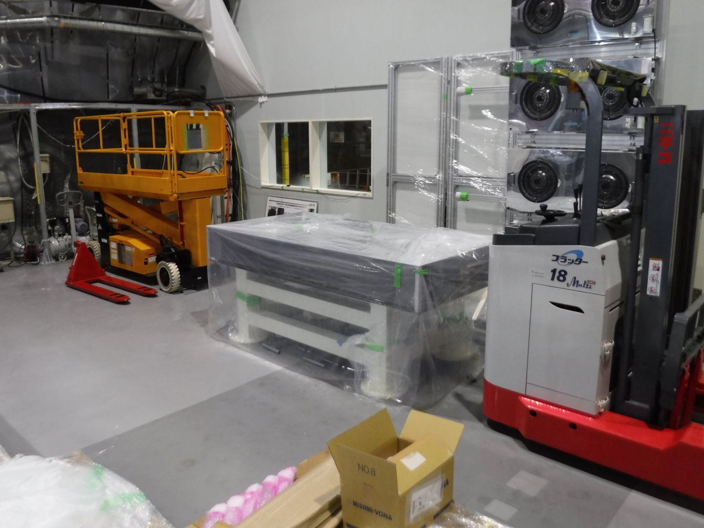
We moved out a POS table with Hayakawa-san and others using Bishamon.
The table is now on the east side of the OMC outside the clean room (wrapped).
The picomotor cable was delivered so we connected contacts and the cable
is ready to be installed in the chamber.
We tried to add one more contact on the DCPD preamp input cable inside the
chamber so that we could drive Zswitch but it turned out the contact from
accuglass is a bit thicker than the one for cosmo-tech. We ordered a new
contact from cosmo-tech and it will be delivered this friday.
otabe, nakashima, somiya
We brought the fixed preamp to the tunnel and tested it, but the result
was unsuccessful. The other two op-amp had gone bad.
When we made a mistake and the dsub was right side left, the -15V was
connected to the output of the PD2 (labeled "1" on the circuit board).
The +15V was connected right as the pin number was 3. This explains
why the PD1 was saved.
We decided to try locking the OMC with the PD1 alone. We connected the
cables and saw the signal in the OMC model of the digital system. We
drove one of the PZTs to generate a dither signal at 1kHz (the dither
frequency in aLIGO is 4kHz but the PZT is 4 times thicker in KAGRA).
We succeeded in seeing something after the demodulation but could not
lock the OMC.
otabe, nakashima, somiya
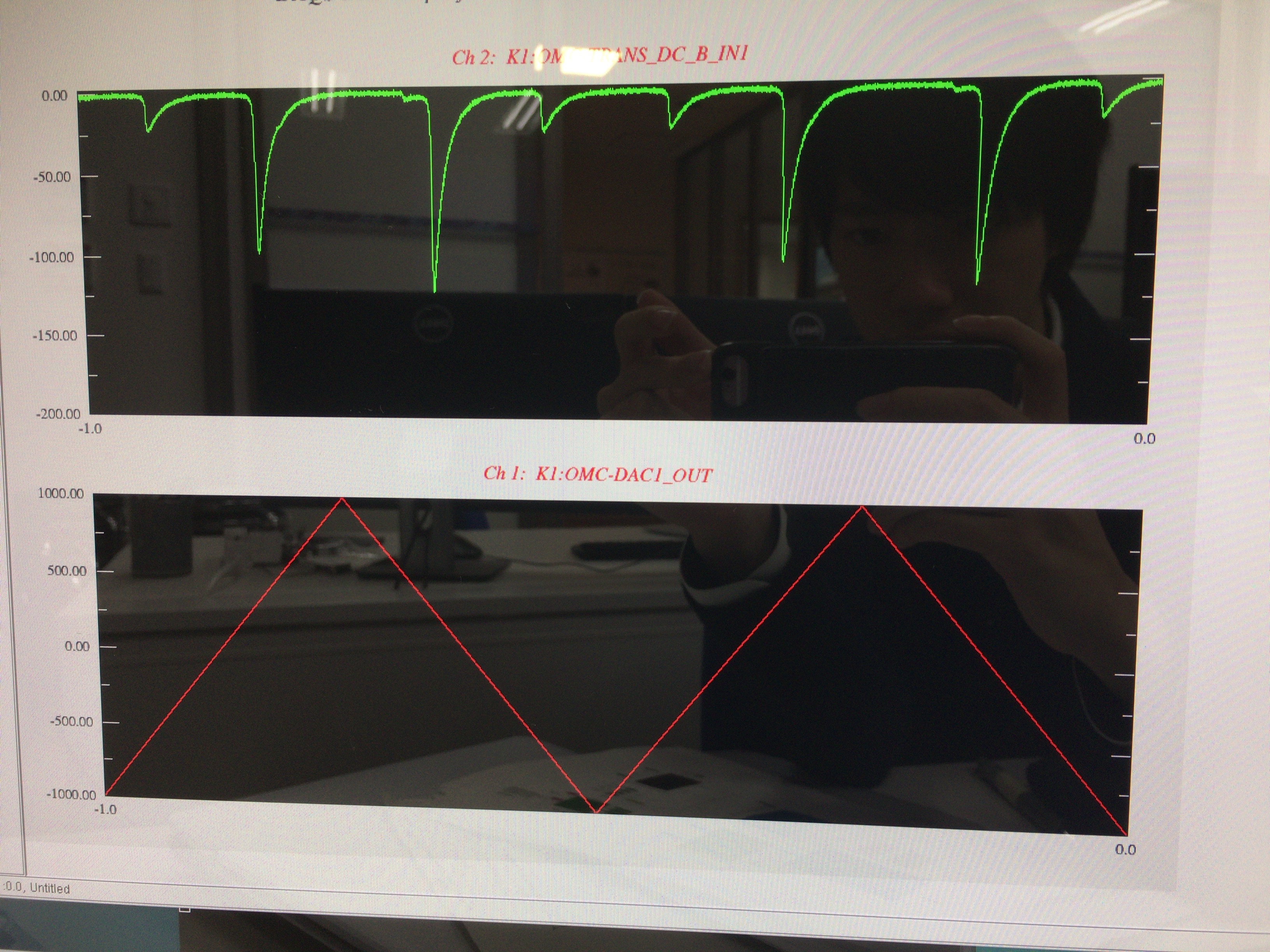
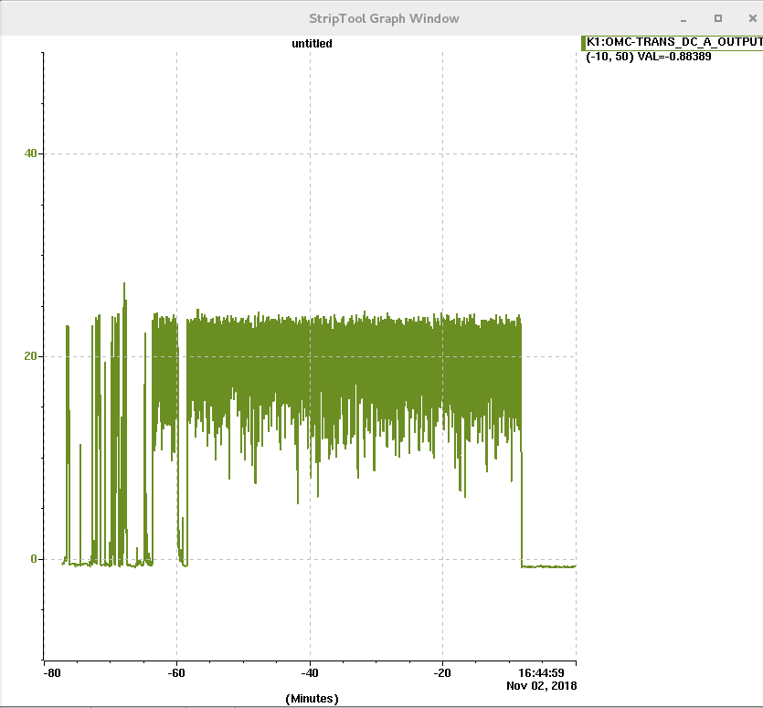
We succeeded in locking the OMC! (See the attached screenshot.)
We turned on the laser in the morning and went back to the control room in Mozumi to
work on the digital system. The transmission went low once but it went back in short,
which was probably not due to the mis-alignment as we did not see a higher mode.
Arai-san found some errors in the model and it was because we did not restart the
system after we changed the OMC model. Yamamoto-kun helped us and the error disappeared
once. Tuning some parameters, we succeeded in the end of the day.
otabe, nakashima, somiya

We connected the Zswitch channel for the DCPD preamp to an open port of the PZT
driver through an unused connector of the feedthrough. The invac Dsub cable for
this usage is the one used for the slow shutter in the IMM, which has been dis-
assembled. One side of the cable is connected to the feedthrough and the other
side is connected to the 5th pin of the DCPD preamp cable. See the wiring diagram
of JGW-T1809176 for the detail.
We also connected a ribbon cable for picomotors to the same feedthrough. All the
ports of the feedthrough were connected and the flange has been closed.
We asked Mirapro people to rearrange the in-air Dsub cables so that the male
connector side comes to the DGS rack and the female side comes to the feedthrough.
somiya and otabe
Michimura-kun and Nakashima-kun fixed and tested the DCPD preamp circuit that
we broke by connecting -15V to the opamp output. Nakashima-kun brought it from
Tokyo Tech and we tried to see the signal through the new preamp, but it turned
out that the AI for the PZT driver was not working properly and we gave up testing
the preamp.
First we found that OUT2 sends out 15V. This started happening actually a few
weeks ago; we stopped using this channel and used the other PZT to lock the OMC.
Today we found that OUT3 does not send any signal. We asked Miyakawa-san and we
replaced the AI (S1605680) by another one found in the GW office 3F (S1402623).
Then we found that OUT2 sends out some signal but with large noise. We asked
Miyakawa-san again for a help and he pointed out that the problem would be coming
from the fact that we tried to measure the OUT2 with an oscilloscope as the neither
the plus or minus of the AI output is GND.
In addition to the wrong usage of an external oscilloscope, we found that our way
of driving PZTs was not appropriate. We convert the plus and minus outputs of the
AI to the signal and ground of the commercial PZT driver through a hand-made Dsub-
BNC converter circuit. As the commercial PZT driver is not grounded (unlike the
oscilloscope mentioned above), this connection would not immediately cause a trouble,
but a proper way is to combine the differential outputs to make a single output
and connect it with a right ground of the DAC.
somiya, otabe, nakashima
We brought a new AI to the OMC rack. It seems this is the last one in the GW office 3F.
We then tried to use a Dsub-BNC converter (differential to single) to send a signal to
a PZT. In the beginning we could not find an output from the converter. It turned out
that it was because the BNC ground was not connected to the ground. The converter is
designed to be used with a jumper pin to connect the grounds. After fixing this problem,
we succeeded in seeing a signal sent to the PZT.
We locked the OMC using an error signal obtained from a sum of the two DCPD outputs
demodulated properly at the dither frequency. We then closed the preamp container.
Now all the work that could be done this time has been finished. We will be back to
the mine once the QPD circuit be ready and the OMMTs/OSMT suspensions be installed.
otabe, nakashima, somiya