Uraguchi, K. Nagano, Hasegawa, K. Tanaka, Akutsu
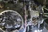
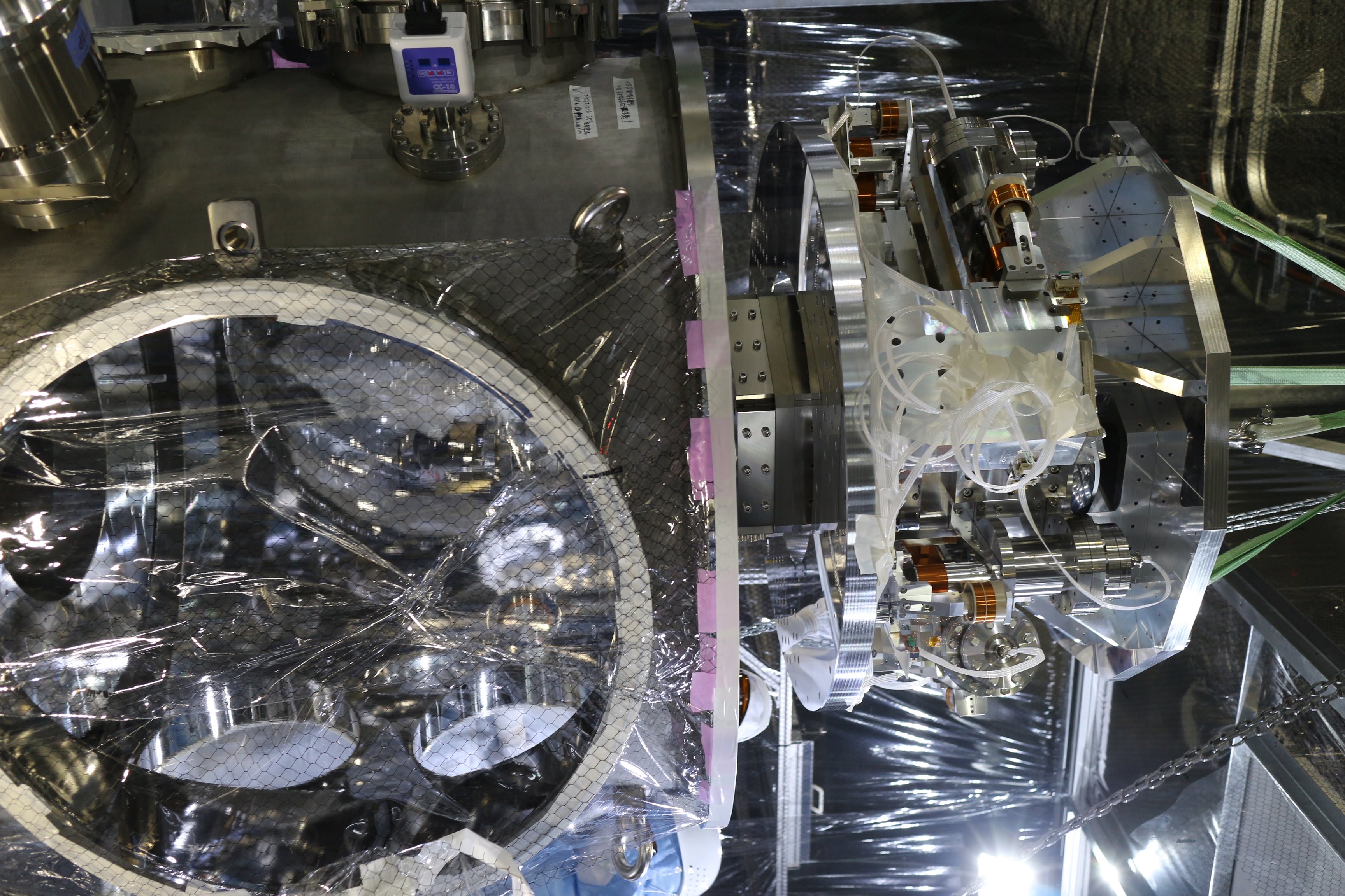
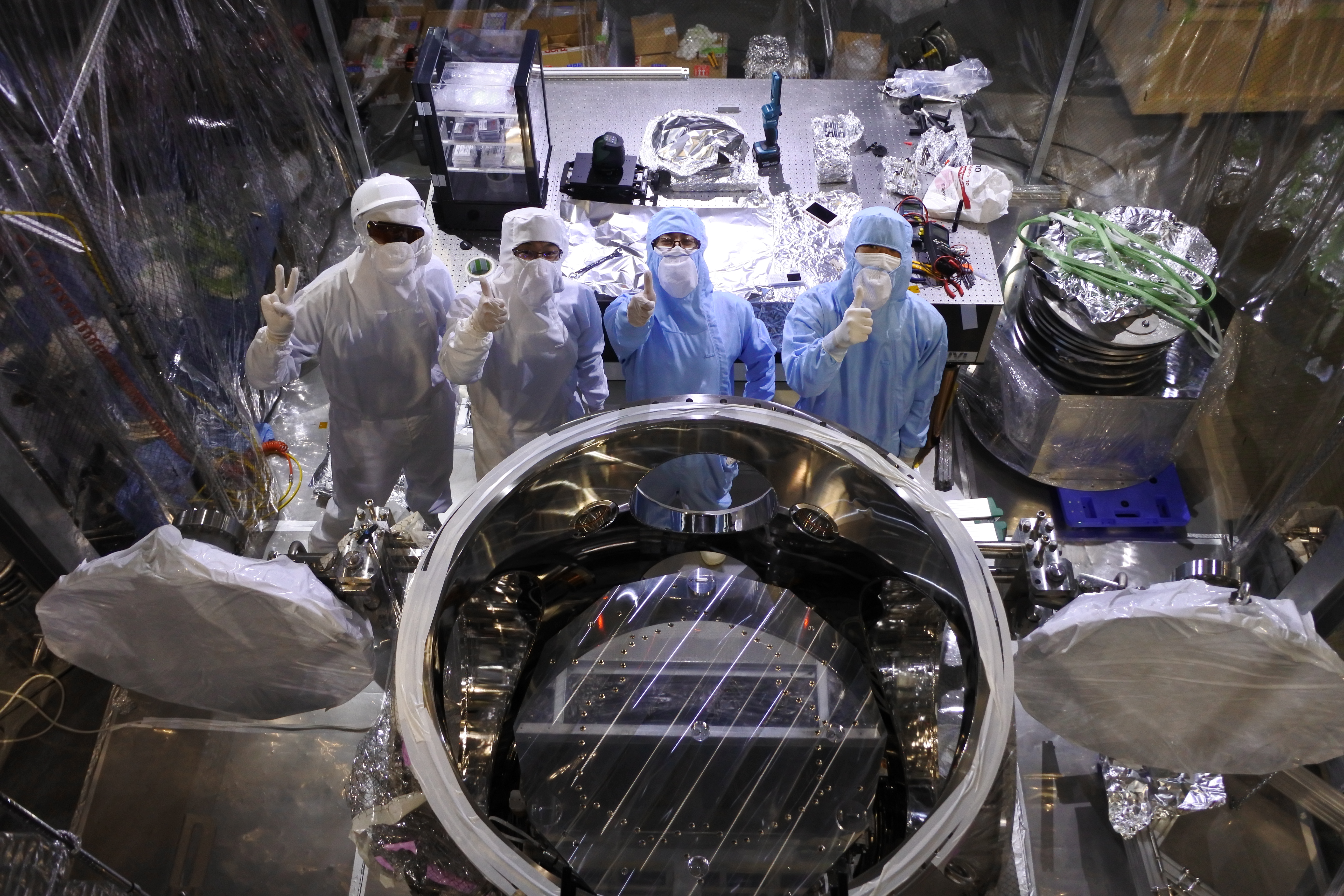
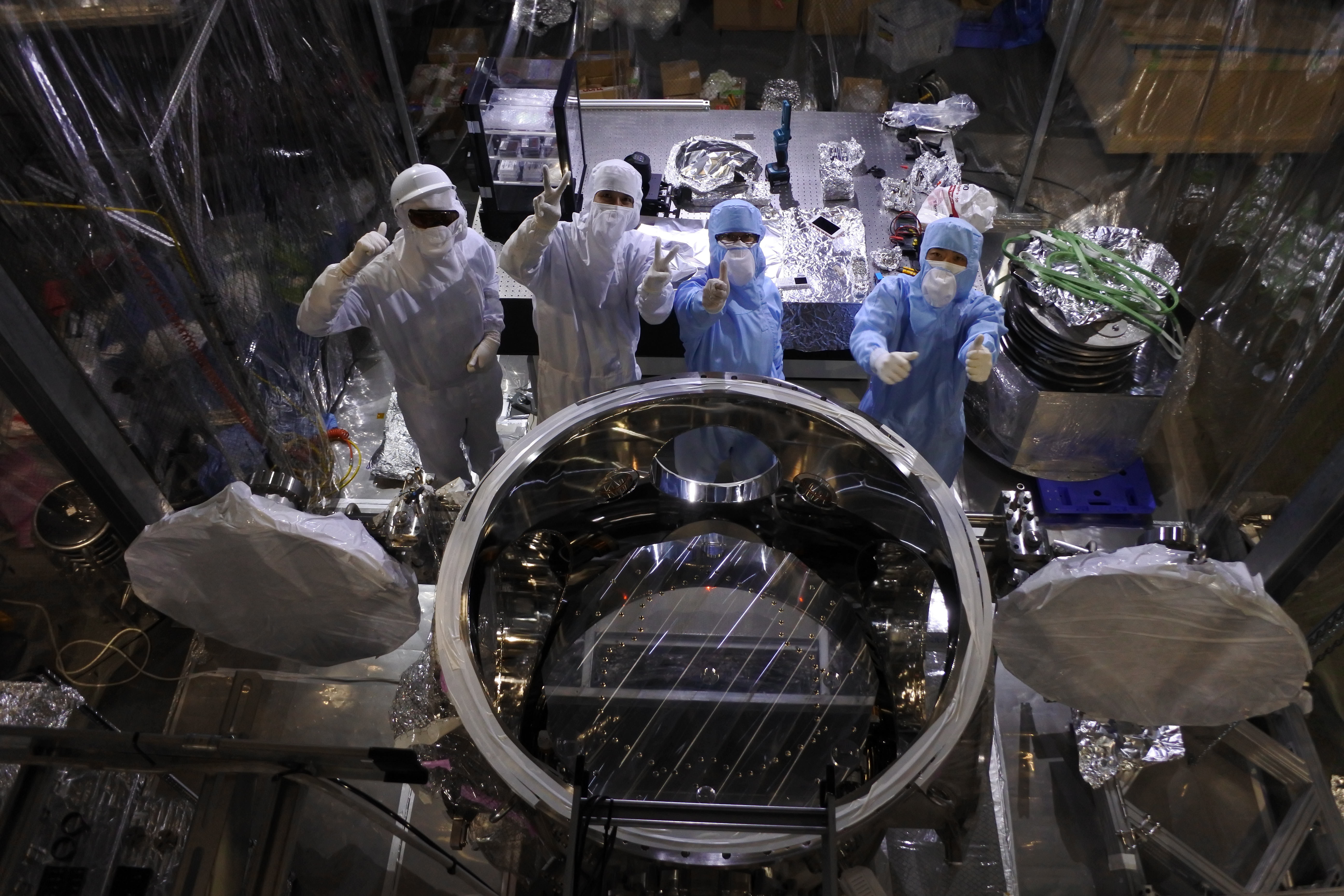
Have finally installed the TMS-VIS into the EXT chamber 
 . The last two in the attached pictures (Fig 15 and 16) show the highlight.
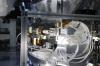
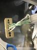
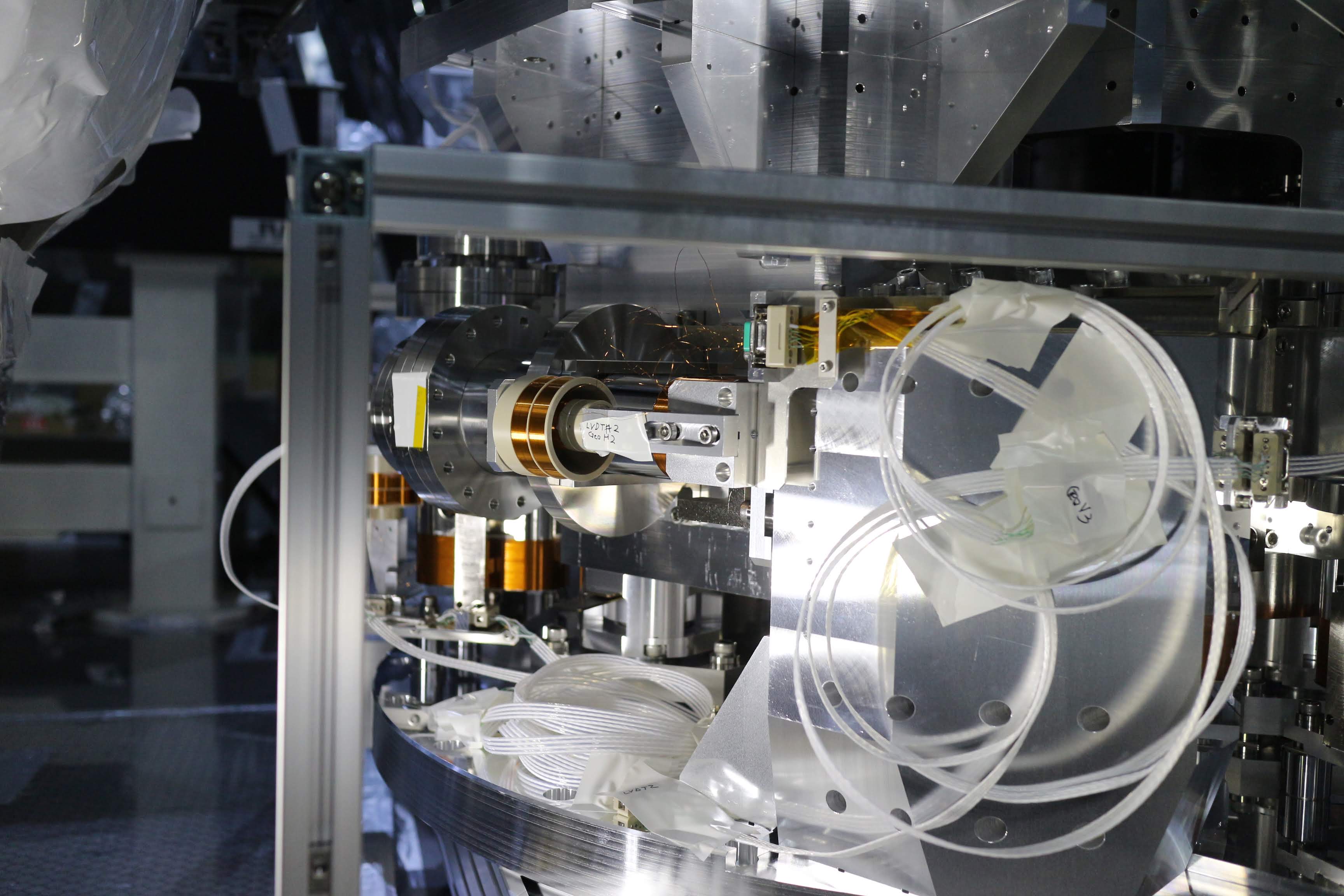
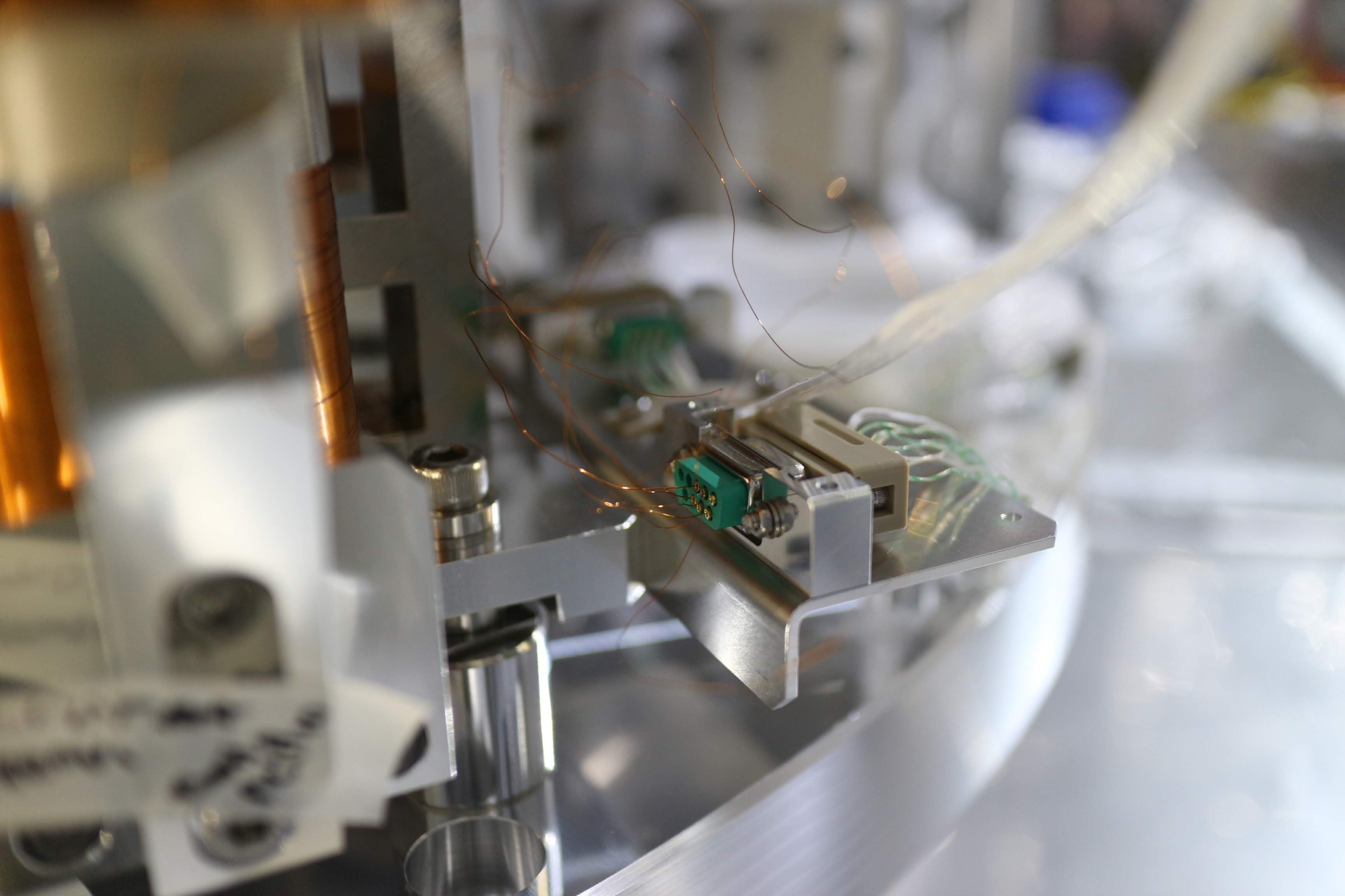
- Before the installation, we connected vacuum compatible cables to the connectors of the coils, and somehow taped the cabes to the TMS-VIS body outside of the EXT chamber so that the cables could be brouht with TMS-VIS (Fig 1 and 2). At some cable connectors (as shown in Fig 1), we wrapped weak necks of the cables by kapton sheet and somehow pushed by PEEK plates to the TMS-VIS body... I hope this worked for releasing the stress...
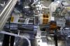
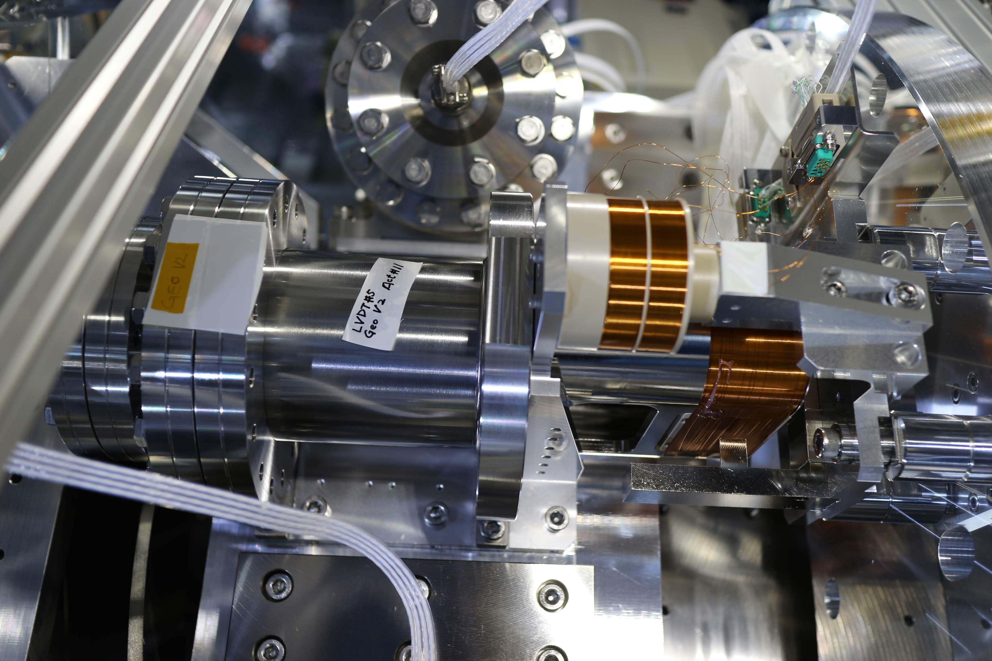
- Inserted kapton sheet between some of the cables and the support plates to keep the electric isolation (Fig 3); note that there are some locations where we cannot do this... (Fig 4)
- Did electric isolation on the repaired part yesterday.
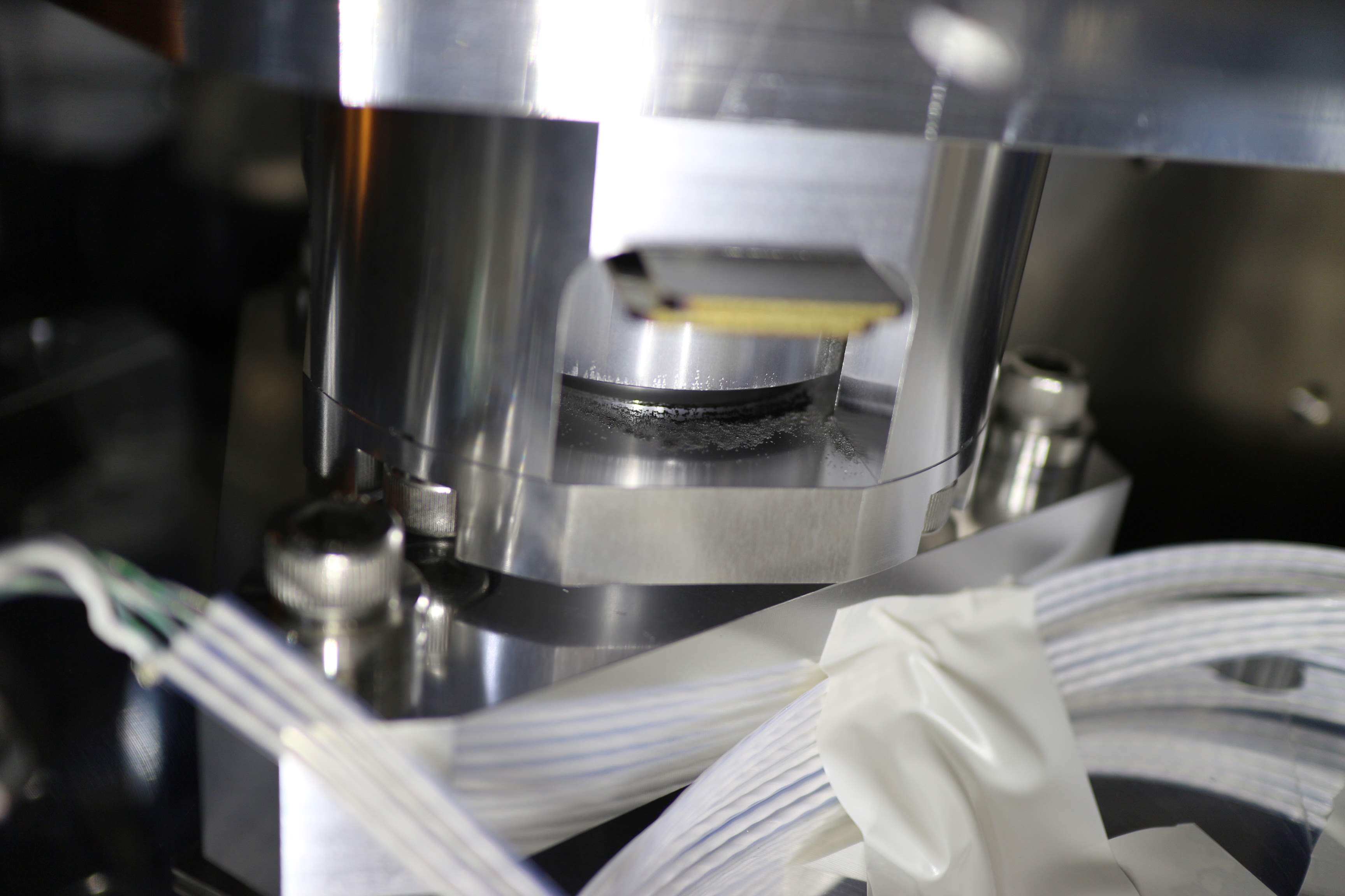
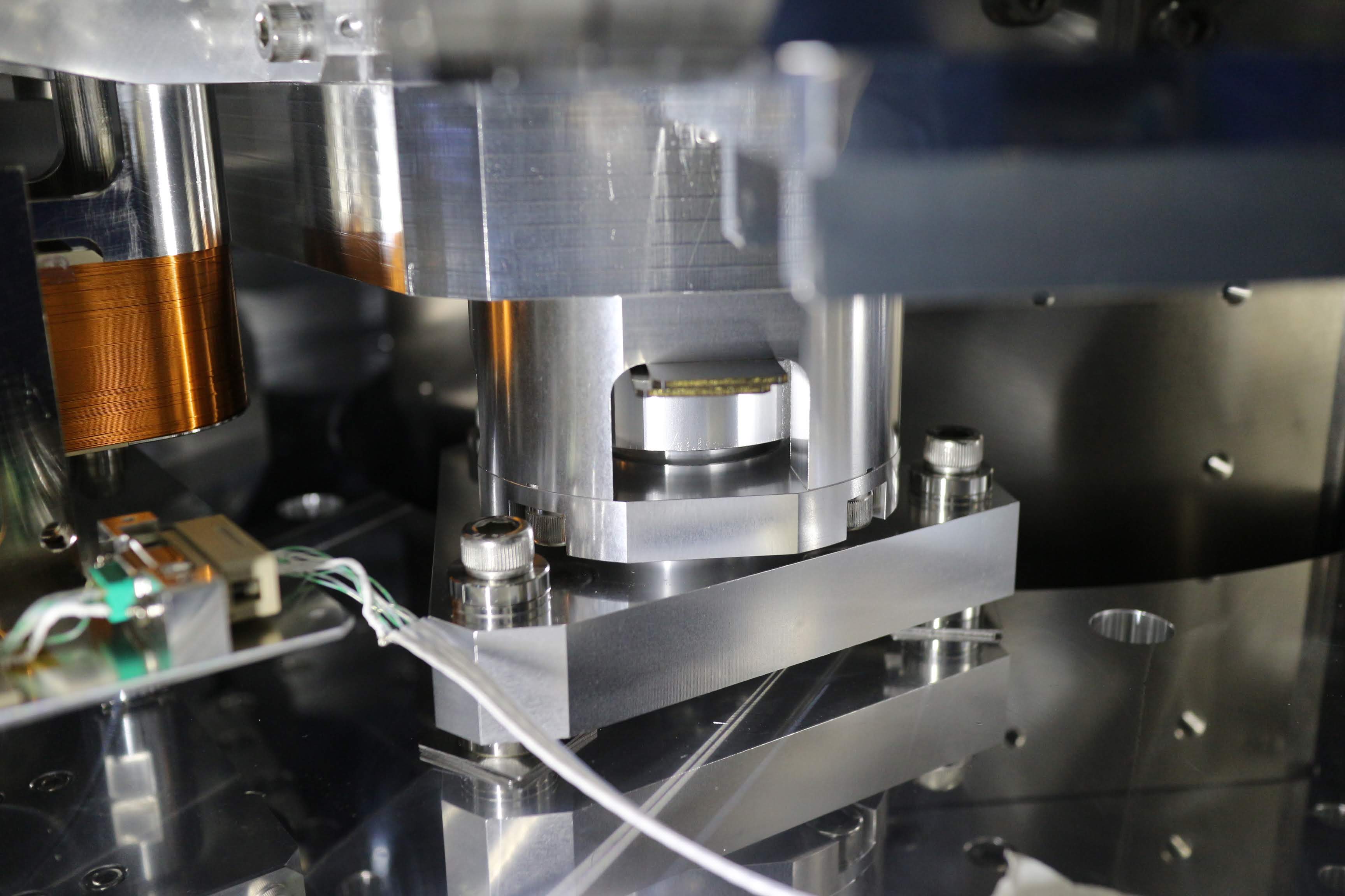
- Wiped out the dust under the limitter structure; the dust would be created by the friction between the shims and the limtter structures during the transportation (Fig 5 and 6).
- Attached three restraints in the horizontal directions to avoid accidents such damaged coils during the hanging work as happened in the last week. There are another three for vertical, but due to the newly designed cable supports, they were not able to be attached... instead of those, newly designed shims were inserted into the limitter so that they could constrain the vertical move of the suspended table part. To do those works, we needed to manage the dummy weight on the suspended table so that the gaps of the limtters should match to the new shims. Finally we removed all the dummy weights on the table top surface. To support the shims, we white-taped them somehow (Fig 7) with praying to a hanging's kami for that those tapes could help not to slip the shims off during the hanging.
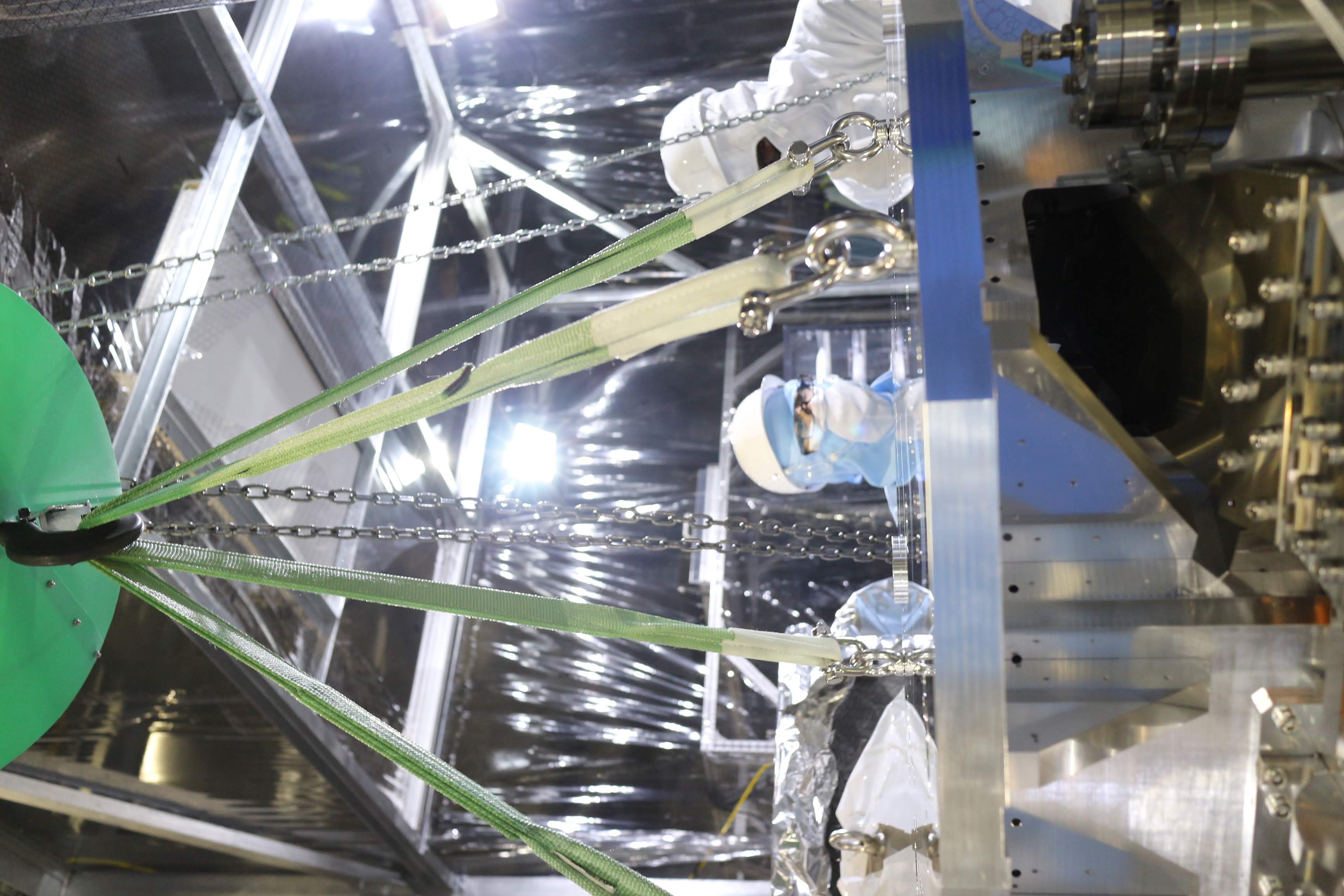
After those preparation, we started the hanging.
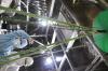
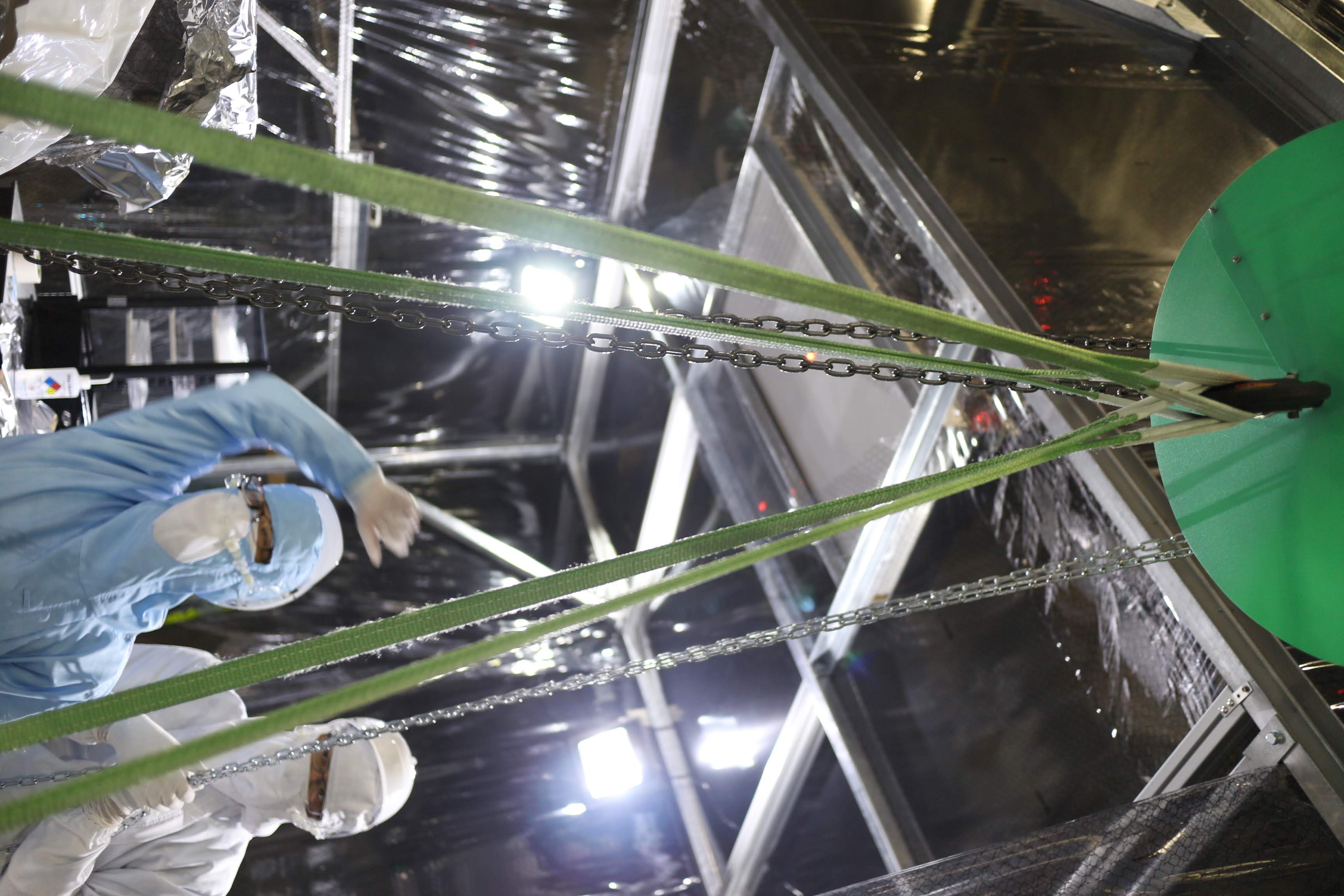
- The lift height was not enough when we used four 1.5 m (20mm width, 0.63t each) belt slings; they were too long (Fig 8). So we just used two 1.5m (40mm width, 1.25t) belt slings (from Mirapro) and hooked at the center then did 4-point hanging (Fig 9). The lineup is here. We got back the Mirapro slings to the original position.
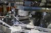
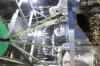
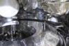
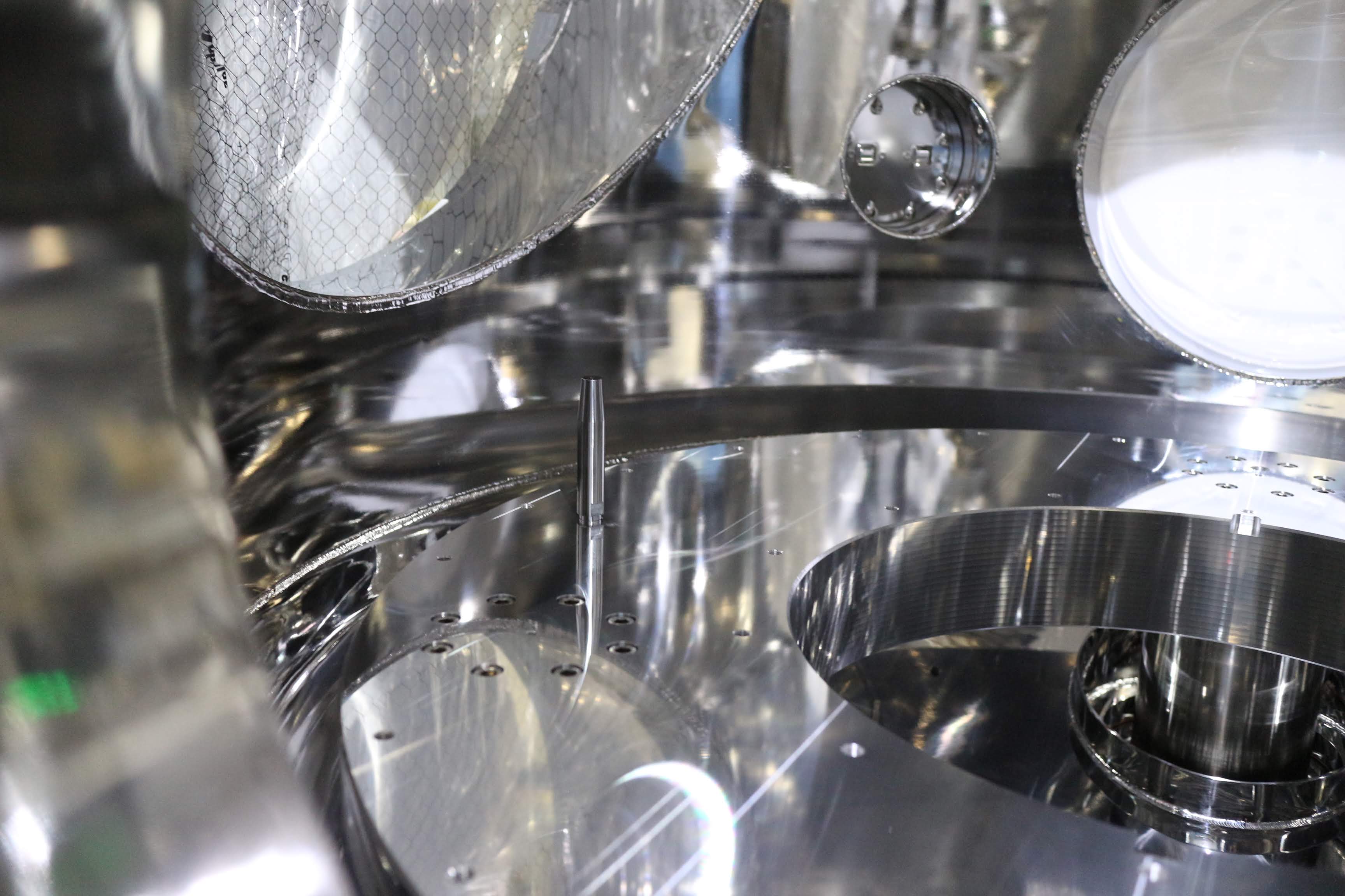
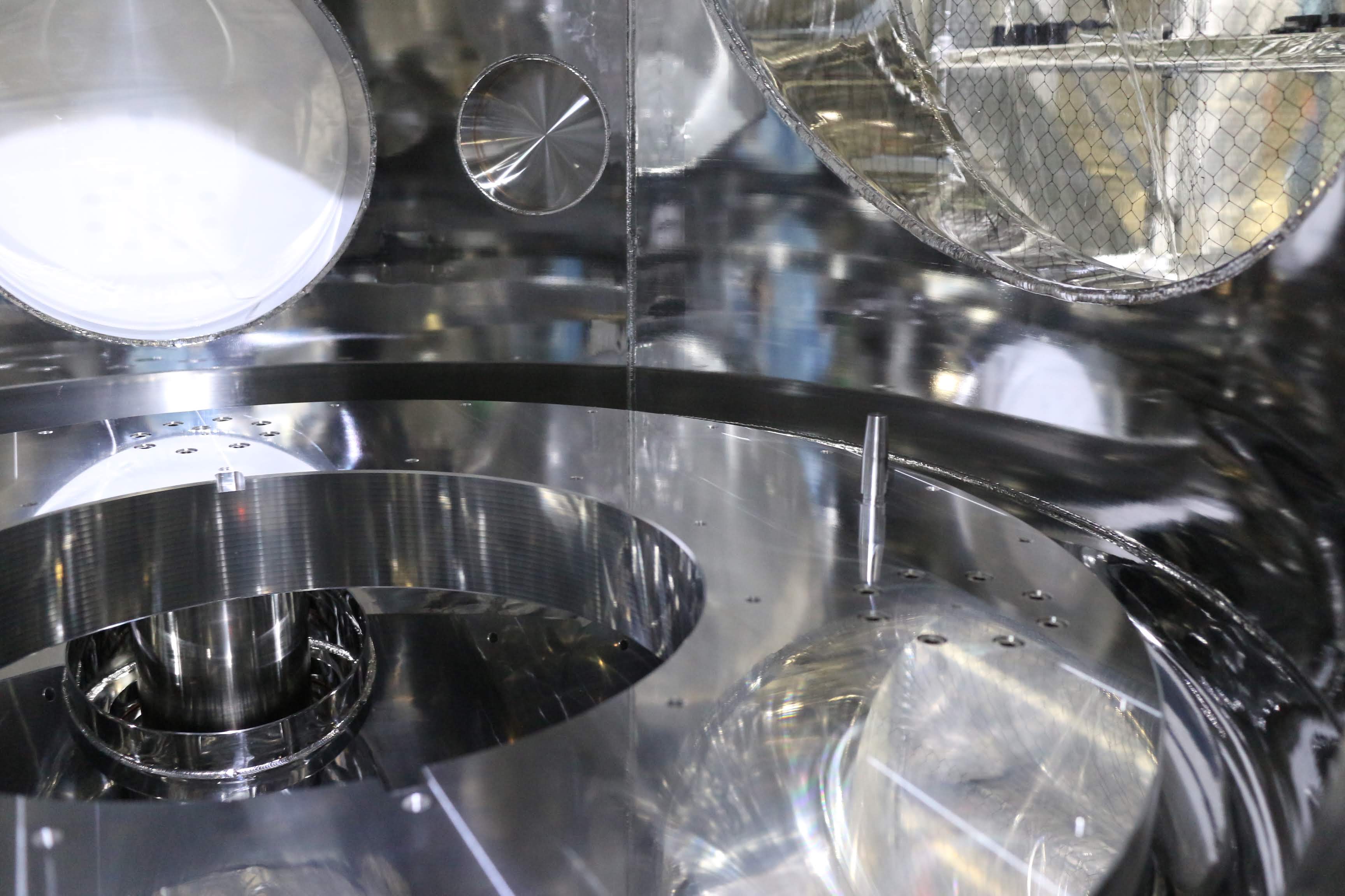
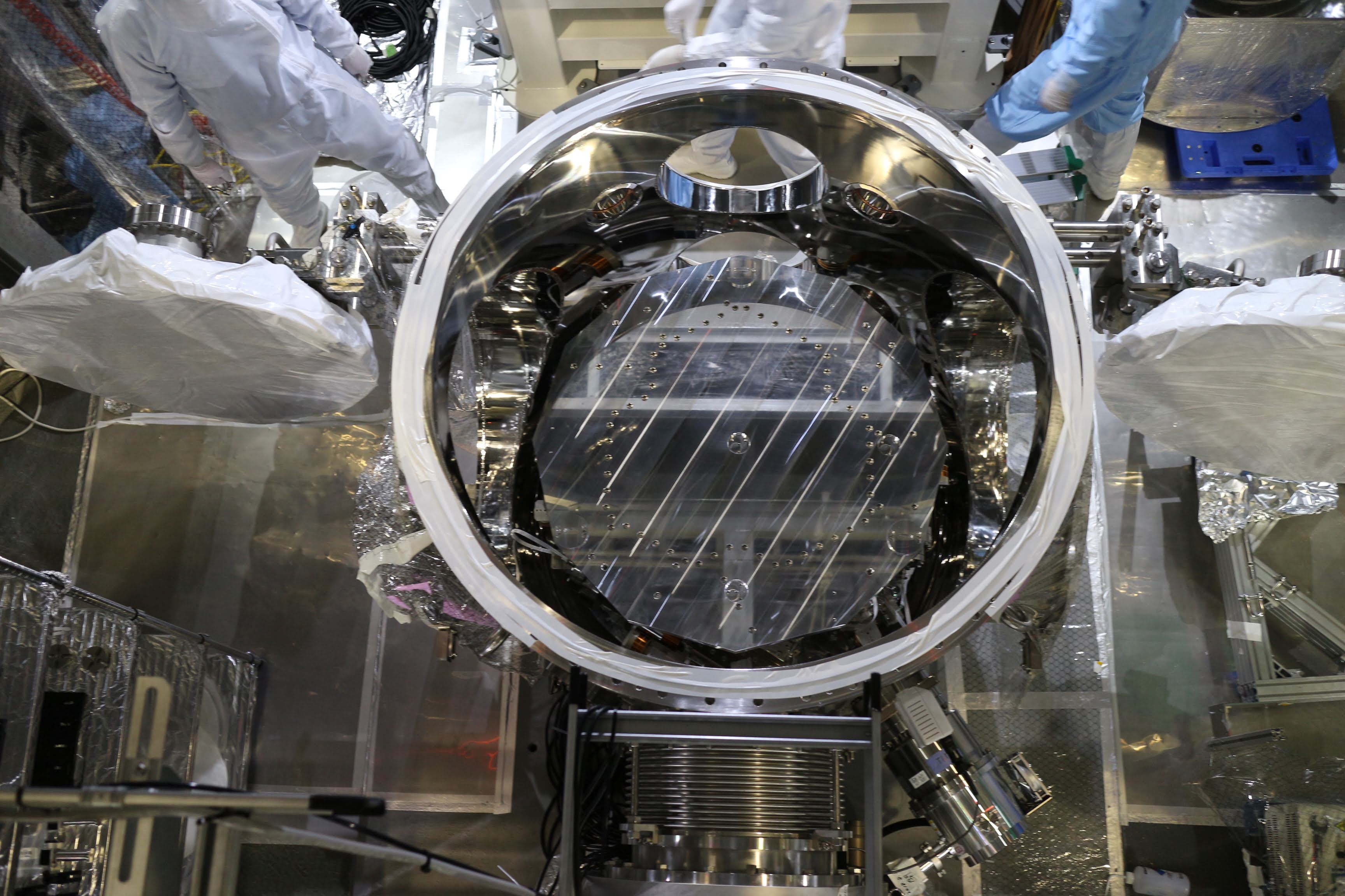
- Our original plan was to use two pins to fix the roll degree of freedom at just the timing when the TMS-VIS was about to sit on the base plate in the EXT chamber; there were a longer pin (Fig 10) and a shorter pin (Fig 11) on the EXT base plate, and the corresponding holes at the TMS-VIS base plate were just a circular hole and a longer slotted hole, respectively. But we found this did not work well, and Uraguchi-san thought the longer pin got a little bit yielded during the first run. So we discarded the longer pin, and put the shorter pin instead (so onle one pin was used); then the shorter pin was facing to the cicular hole. Once the TMS-VIS sit on the base plate of the EXT with the short pin throught the circular hole, we hanged up the TMS-VIS slightly (~ a few mm) again, and we loosely bolted several screws that would fix the base plate (upper) to the base plate (lower), then checking carefully their freeness, the TMS-VIS finally got in the position on the base plate of the EXT chamber (Fig 12 and 13).
By the way, the load I felt from the chain block was quite heavy when the TMS-VIS was hanged up... I have not had the experience to feel such a heavy weight from chain blocks so far!
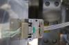
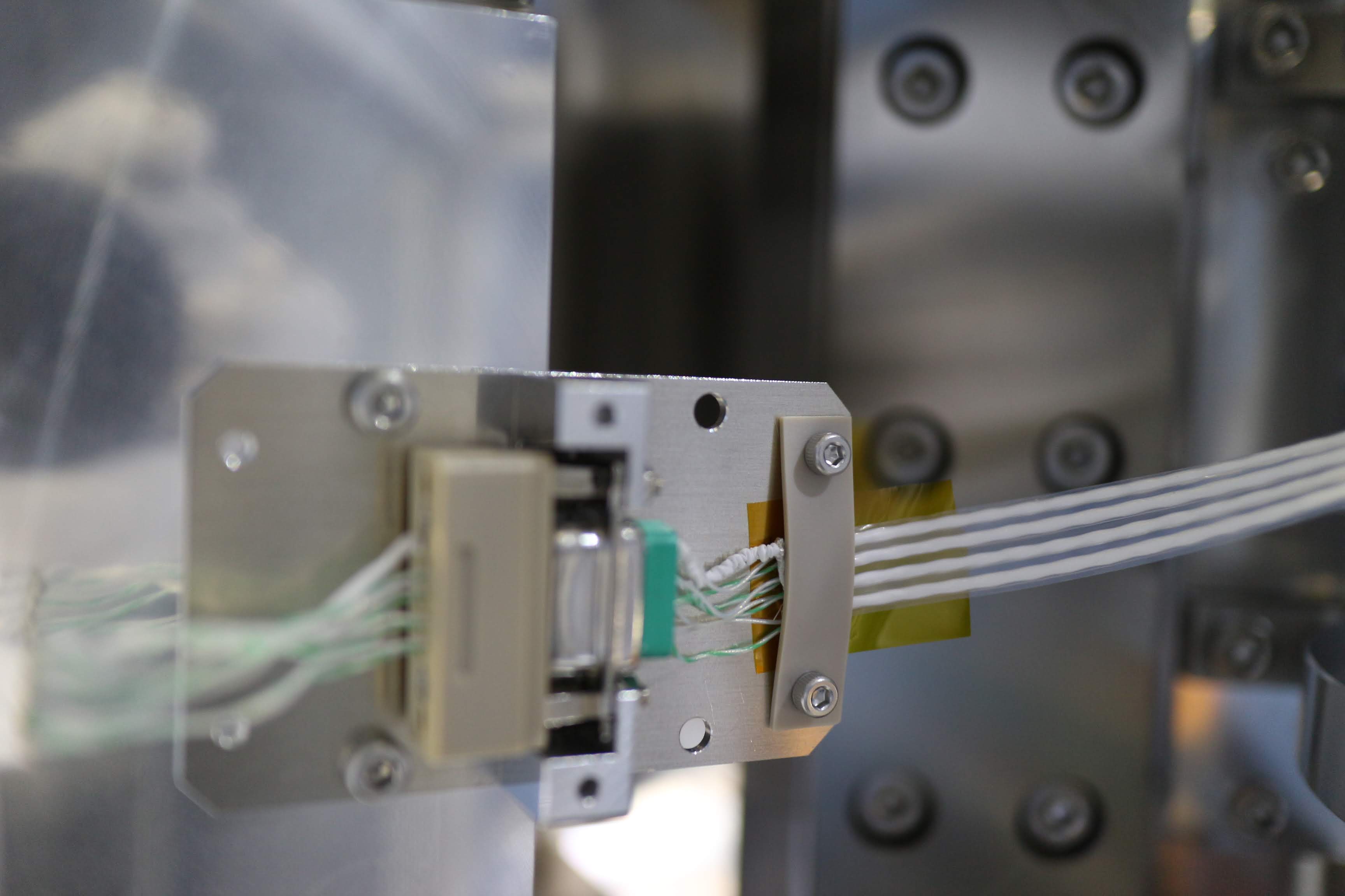
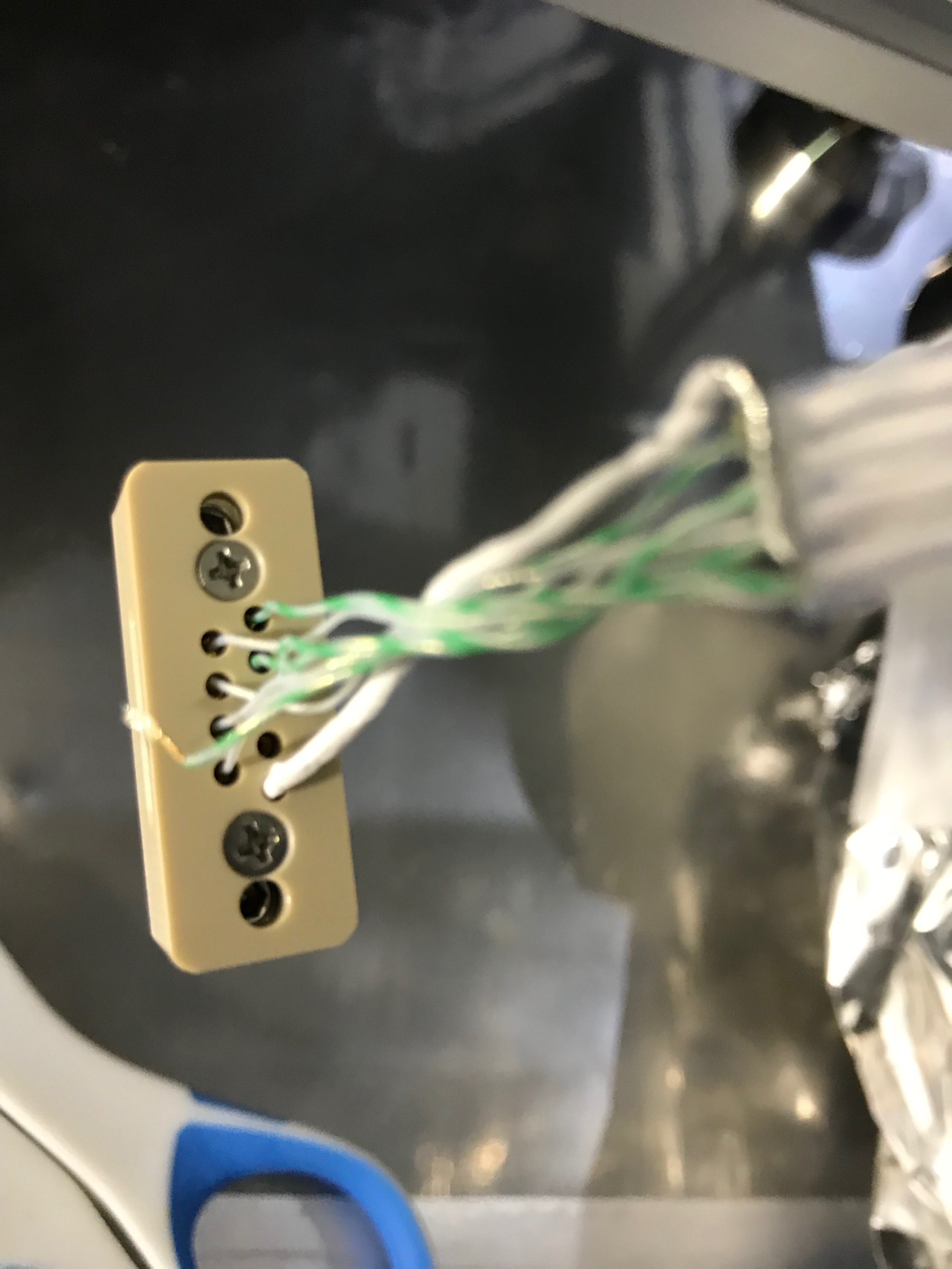
Note: one of the vacuum compatible cable broke at its connector (Fig 14) before starting the hanging (in the preparation works); so I just used this cable for a LVDT as it does not need the electric connection at the point. Anyway the lesson is that the cable is too weak! Should be reconsidered the assembly process of the cables for our future!


