Simon, Yano, Ken Tanaka, Akutsu on 20180904; see also here.
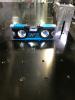
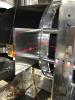
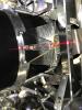
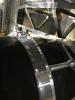
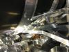
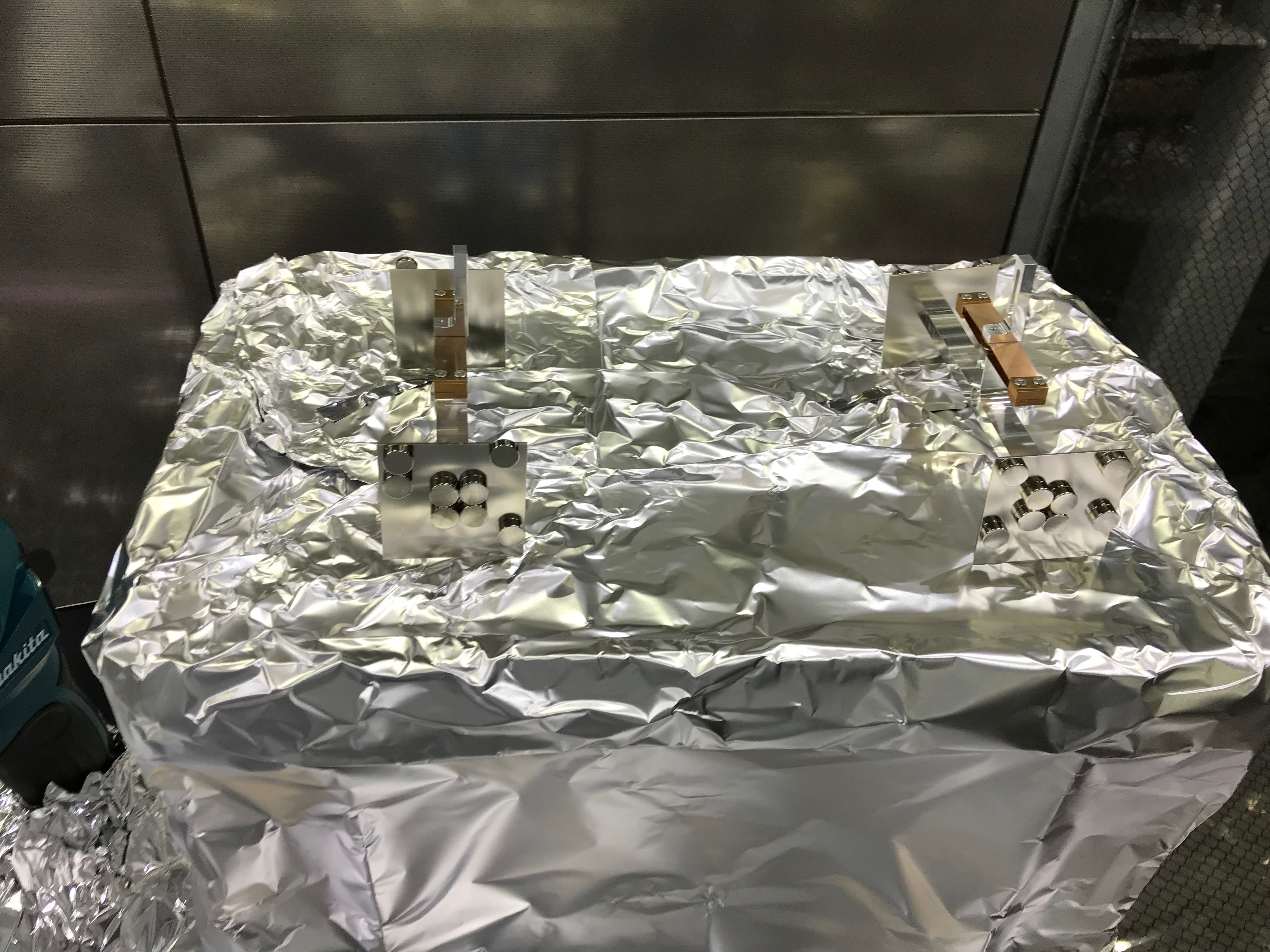
We started with removing the protectors for the WAB's edges and the suspensions to check the balance of the suspended WAB. Then it turned out the SmCo magnets (by the way, for this WAB, the magnets are circular shapes for some reasons) have moved out of their original positions on the damper plates; probably due to mechanical shocks during the transportation. So we detached the magnet dampers.
Making a reference line
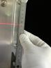
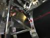
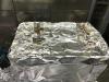
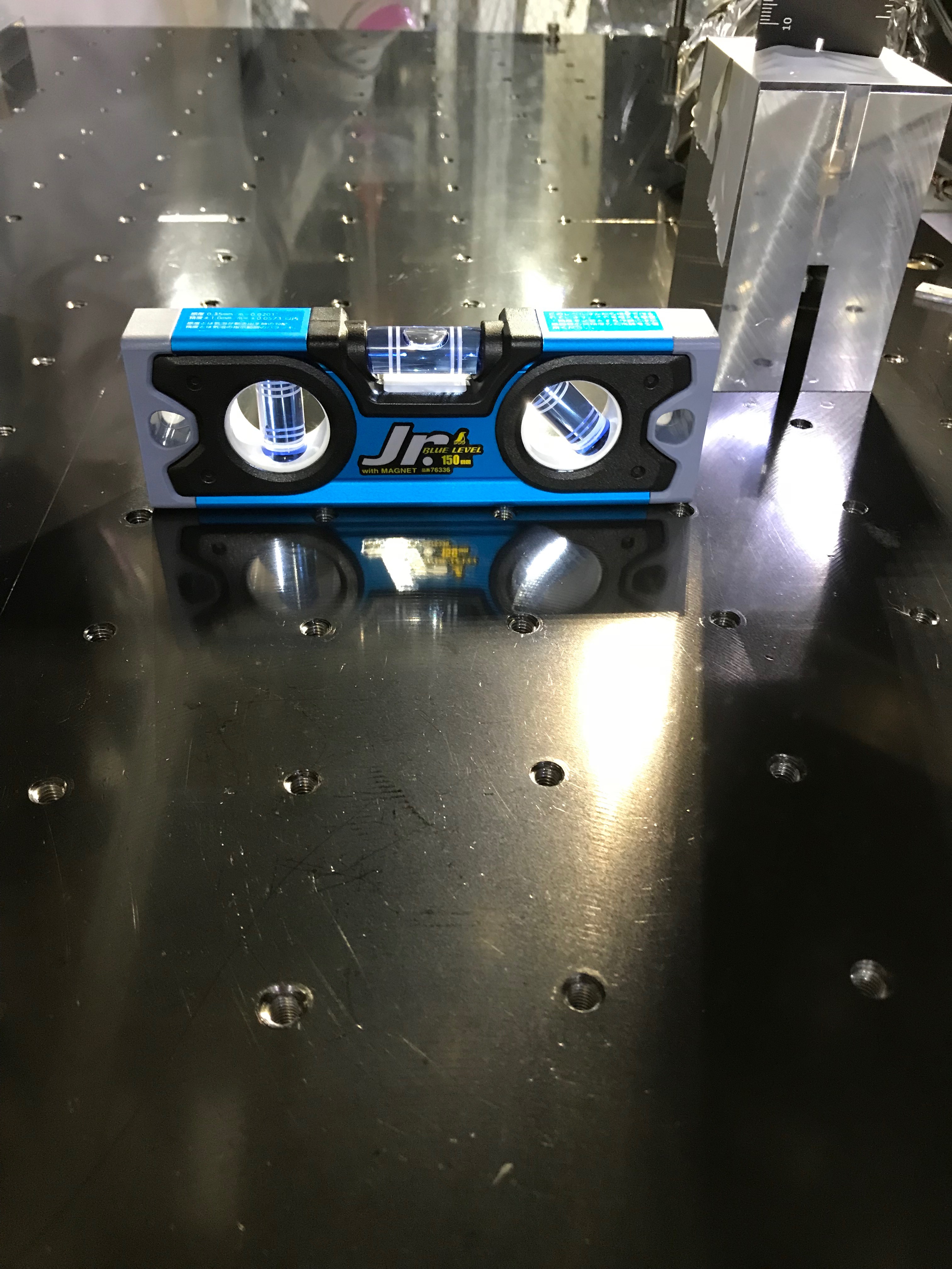
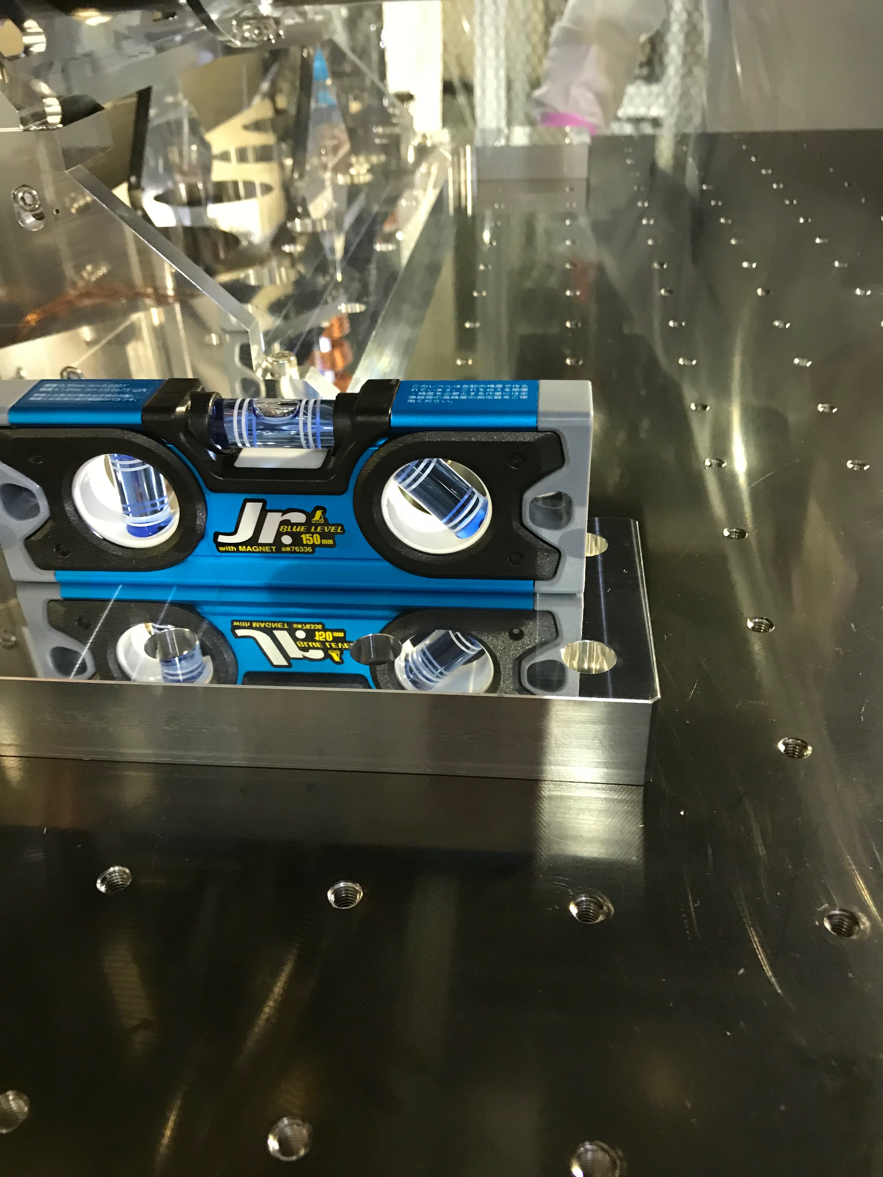
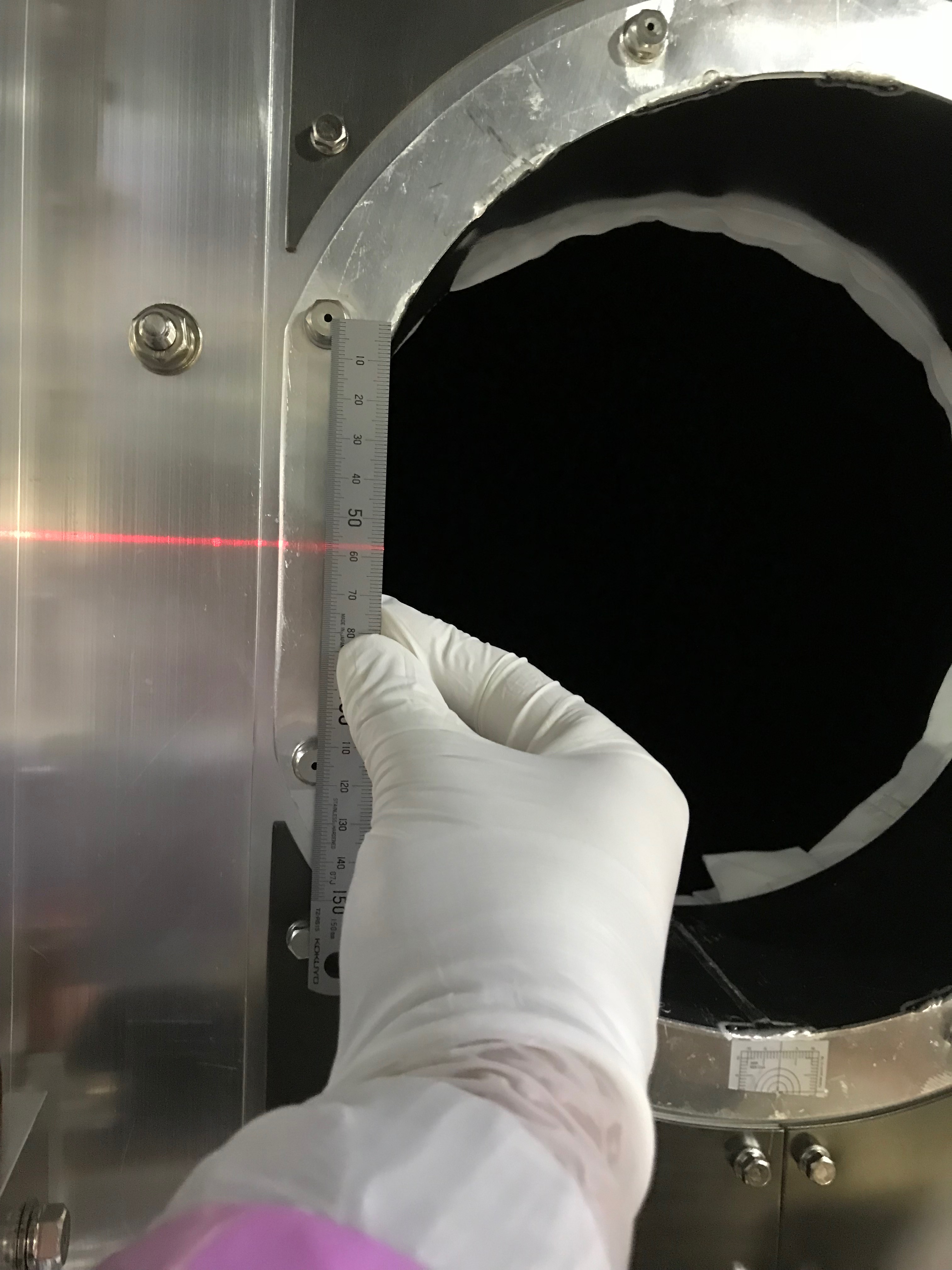
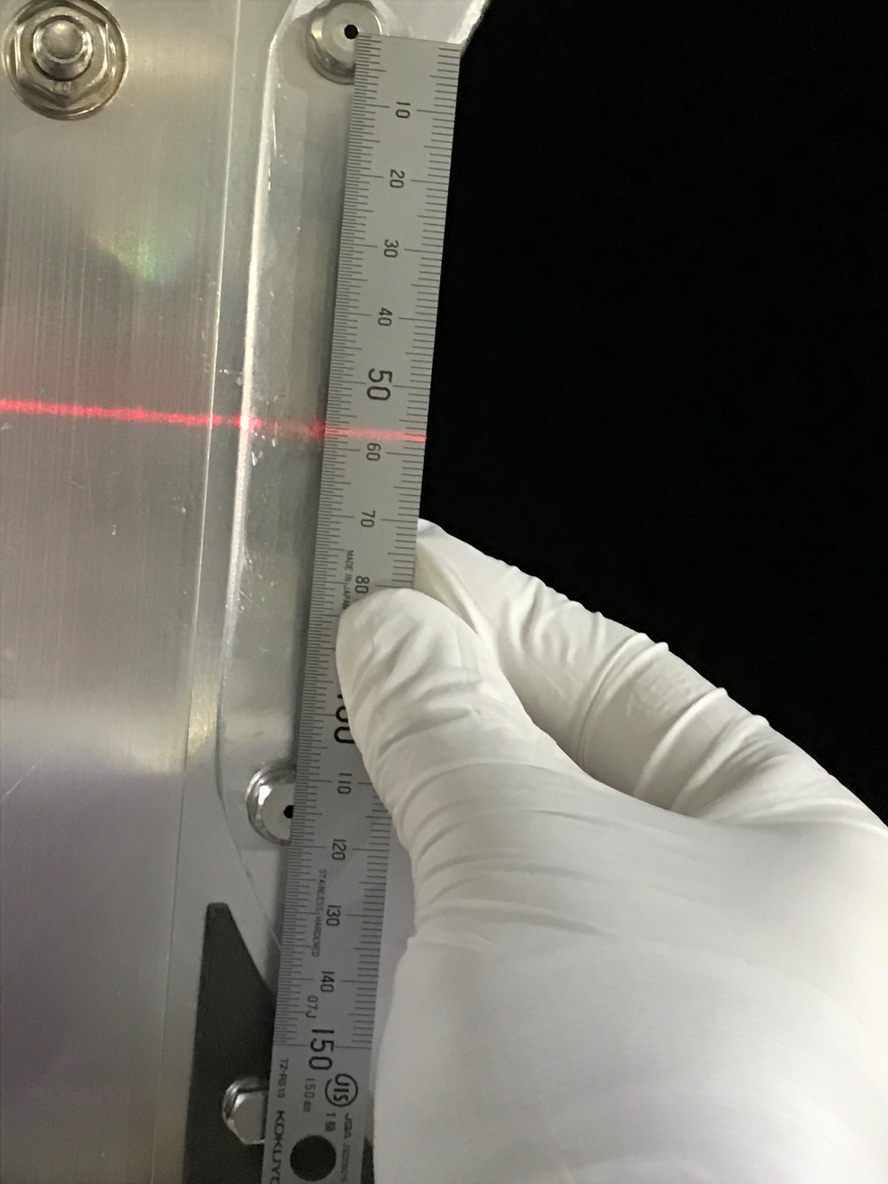
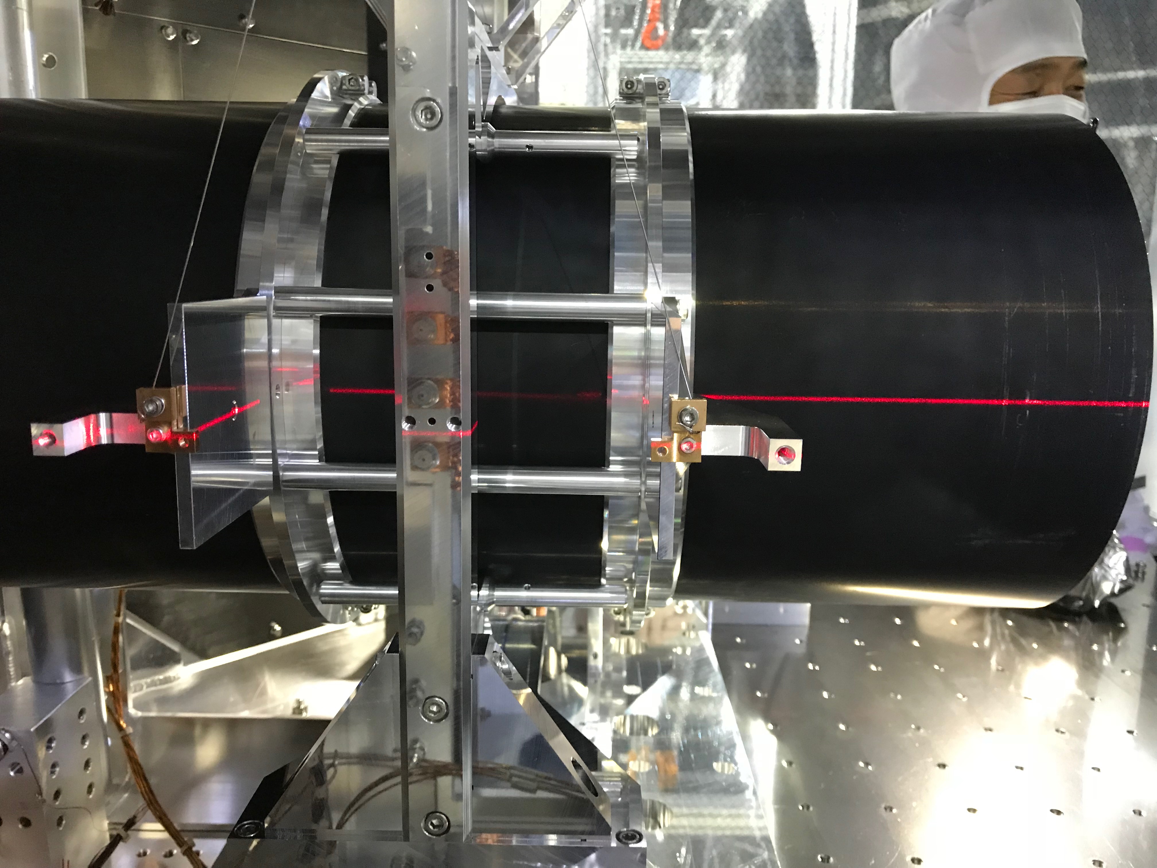
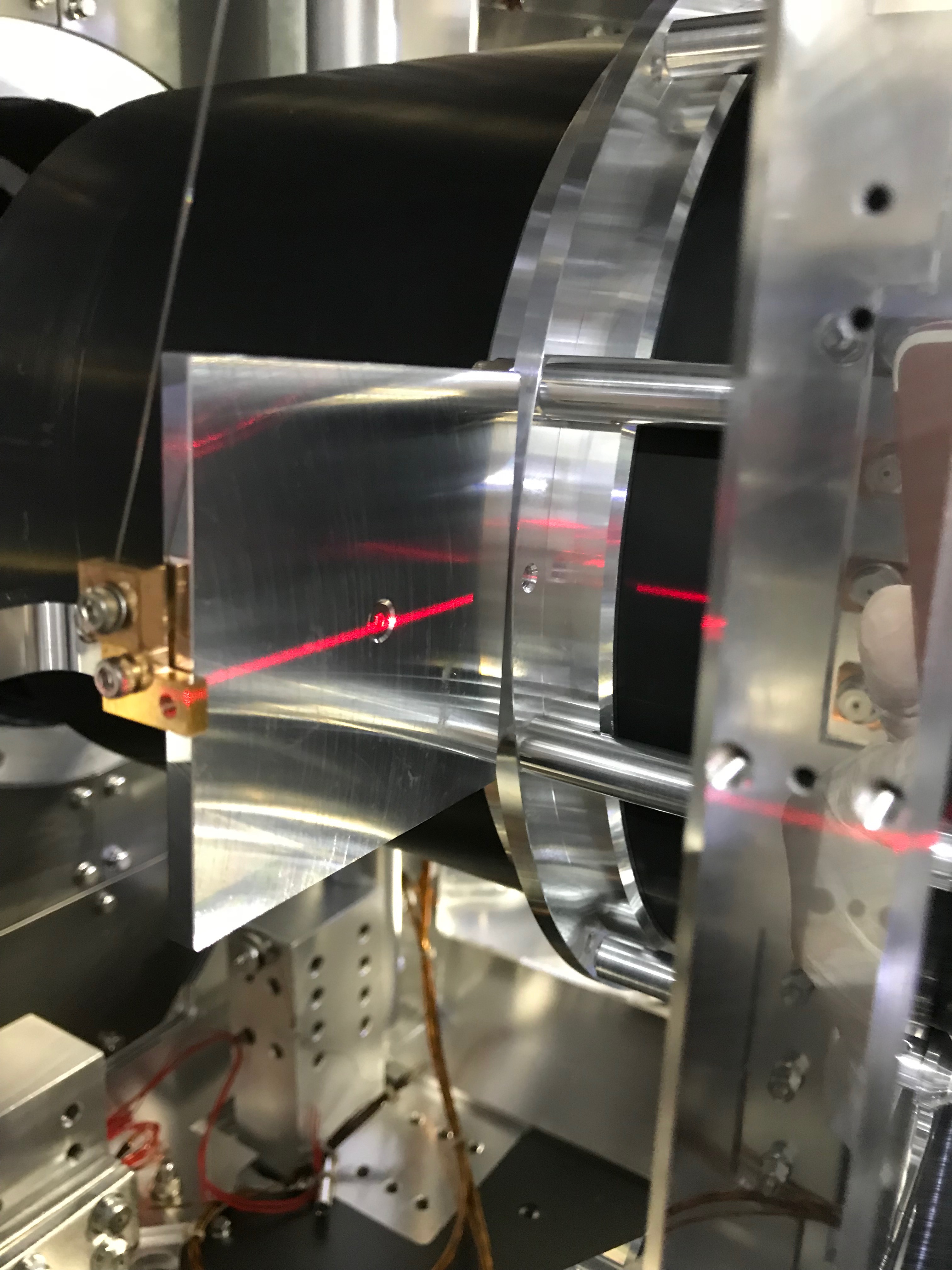
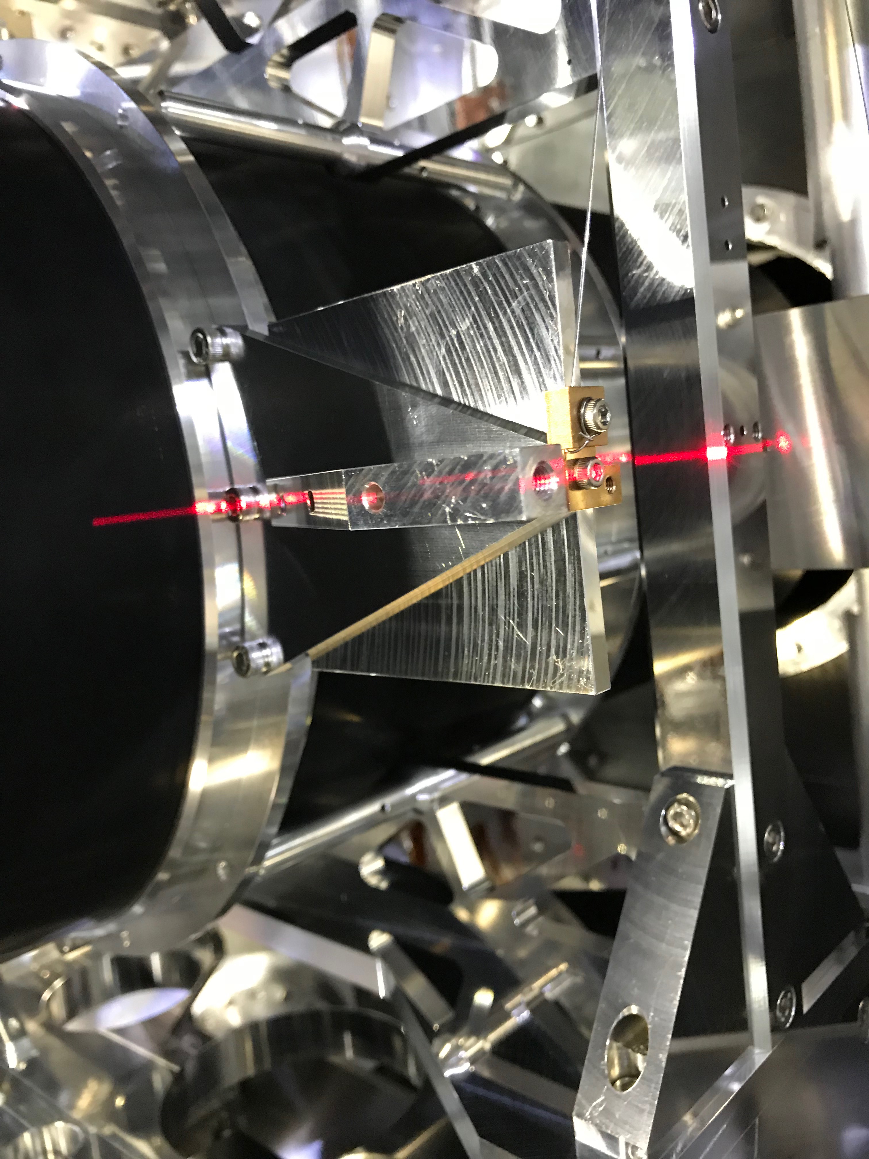
After checking the horizontalness of the breadboard (Fig 1 and 2), we tried to check the height of the suspended WAB. In this chamber, we did not find any useful reference scratches indicating the light-beam height , so we started with making (an) easy reference line(s). Using several screw heads, and among them, especially using heads of two screws that fix the duct-forming part to the 8K shield; the middle of the two heads should be the center of the duct in a certain accuracy and precision (Fig 3 and 4). We left a white tape and put a reference line on it. ...Speaking more precisely, there are several uncertainties (for example, the relative positions of the duct and the true line of the light beam, or the locations of the screws), so it is difficult to say what is the best on this day, but we hoped our reference line could become a reference to some extent. Then the laser line height was measured to be 174 on the vertical ruler, and which corresponded to 174 - 10 + 105 = 269 mm height from the breadboard; here the vertical ruler was attached onto a foot block (we did "laddering" of rulers to measure a height, as we could not find a height gauge with enough height which we have usually used. Here the "minus 10" is to translate the read of the vertical ruler itself, as the ruler's scale starts from "10", while the "105" is the measured height of the first scale line at the bottom of the ruler from the top surface of the breadboard); see Fig 5 and 6. By the way the nominal height of the duct center should be 270 mm, but as described above, there are several sources of errors, we left this as was; you know, there are no other choices, right?
Height (and roll?) check and adjustment
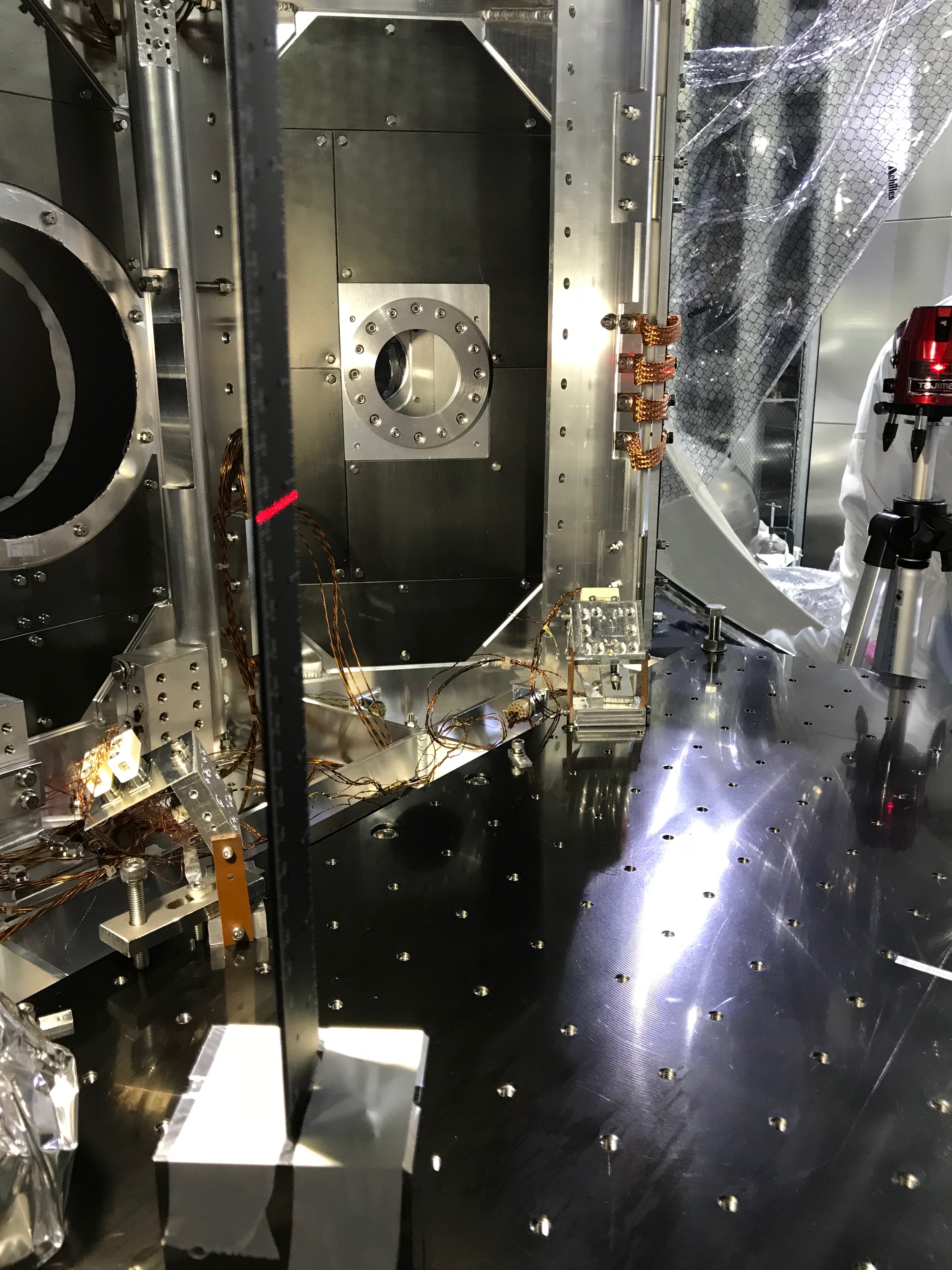
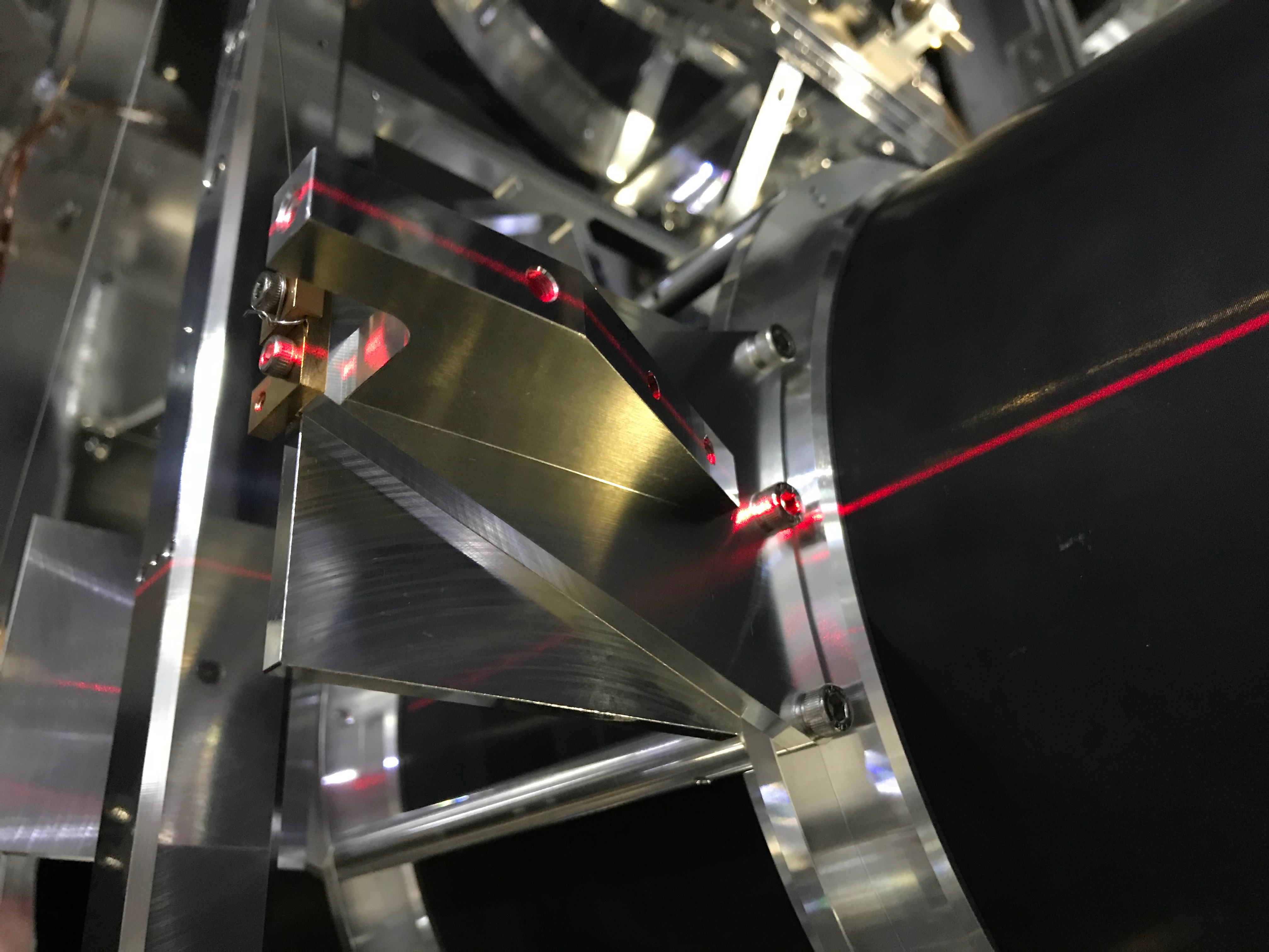
Then we checked the WAB's height; the desired number is -1 mm from the duct center height at room temperature, which should correspond to 173 in the vertical ruler's read. At first, we illuminatd one side of the WAB with a horizontal laser line from the laser leveler to check the WAB's height and got 173 or 173.2, then it was set at the other side and got 174.5. So this indicated a slight rolling (plus vertical shift?) of the suspended WAB. The center of those numbers should be (173.2+174.5)/2 = 173.85. After tweaking the roll by the stages on the suspension structure, the numbers changed to 174 and 173.8 respectively. So the center line is matching with the reference line on the white tape, which is consistent each other, so the roll would be resolved (Fig 7-11). As described above, the WAB would be at 269mm from the top surface of the breadboard.
There still seemed 0.8-1mm height difference from the desired number, but we left it on this day. The reasons are:
- The relative height 269mm is exactly the desrired number as the height of the WAB from the top surface of the breadboard. (Actually we have set to this number at Mitaka then it was shipped to Kamioka)
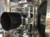
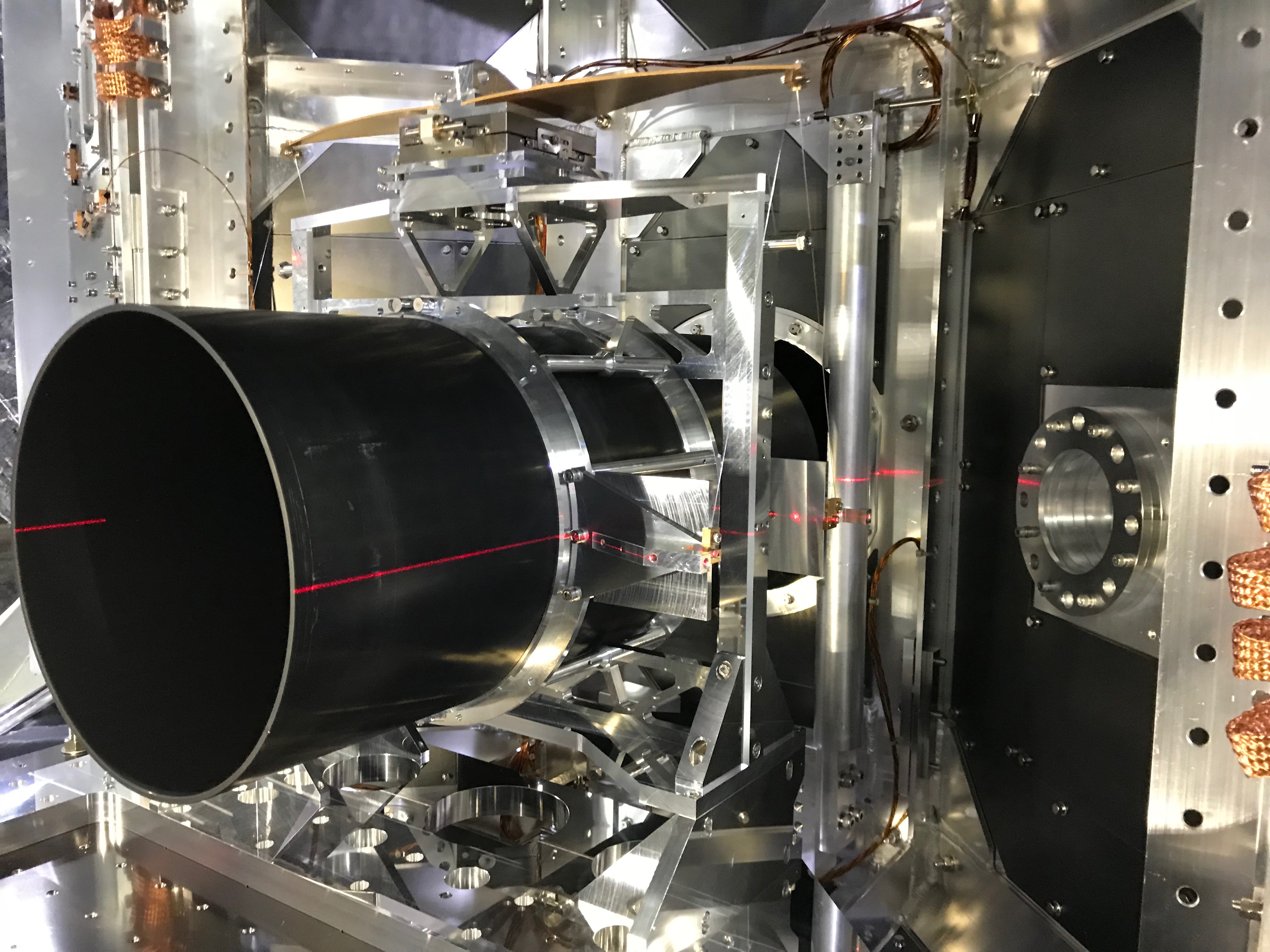
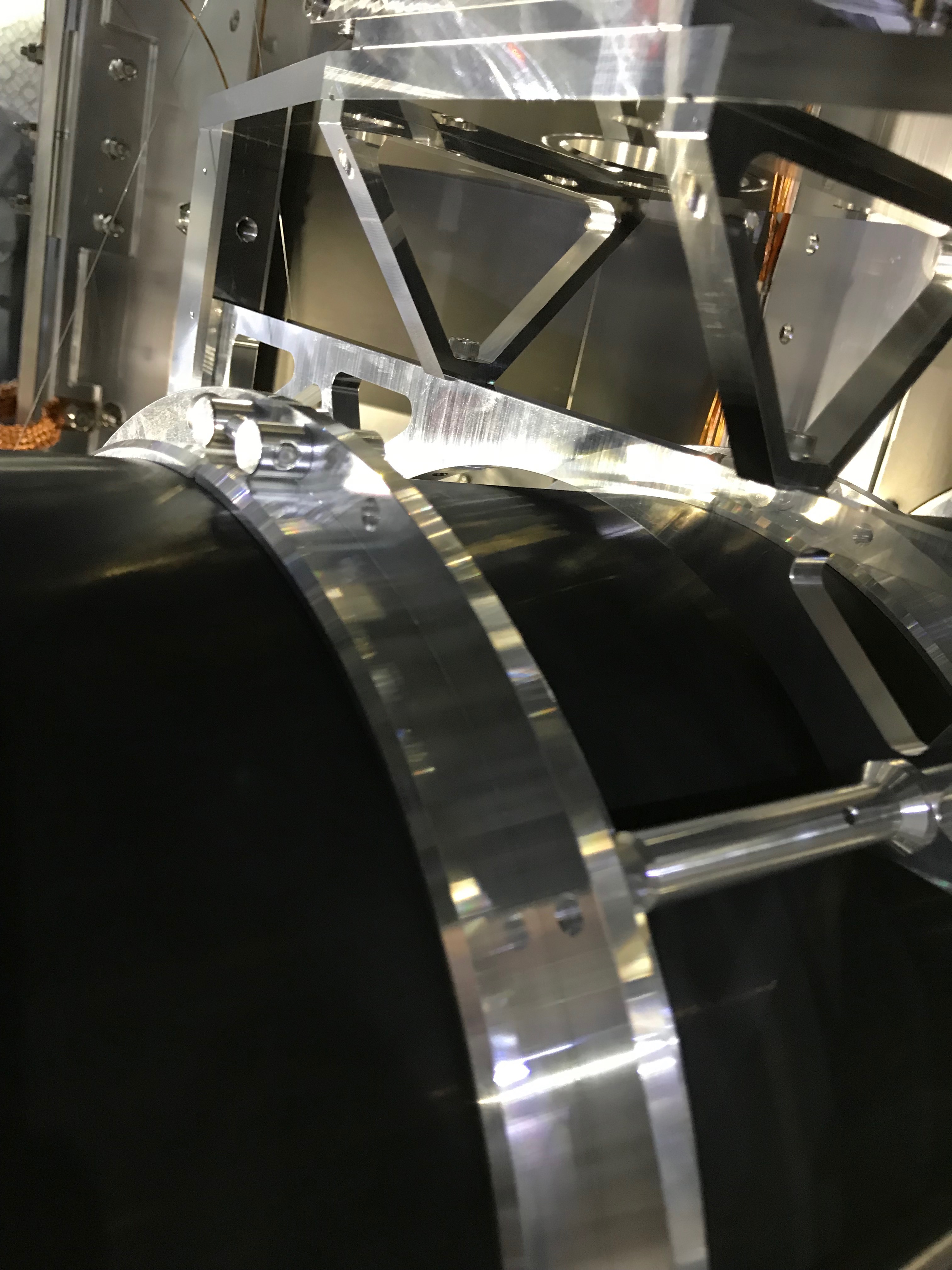
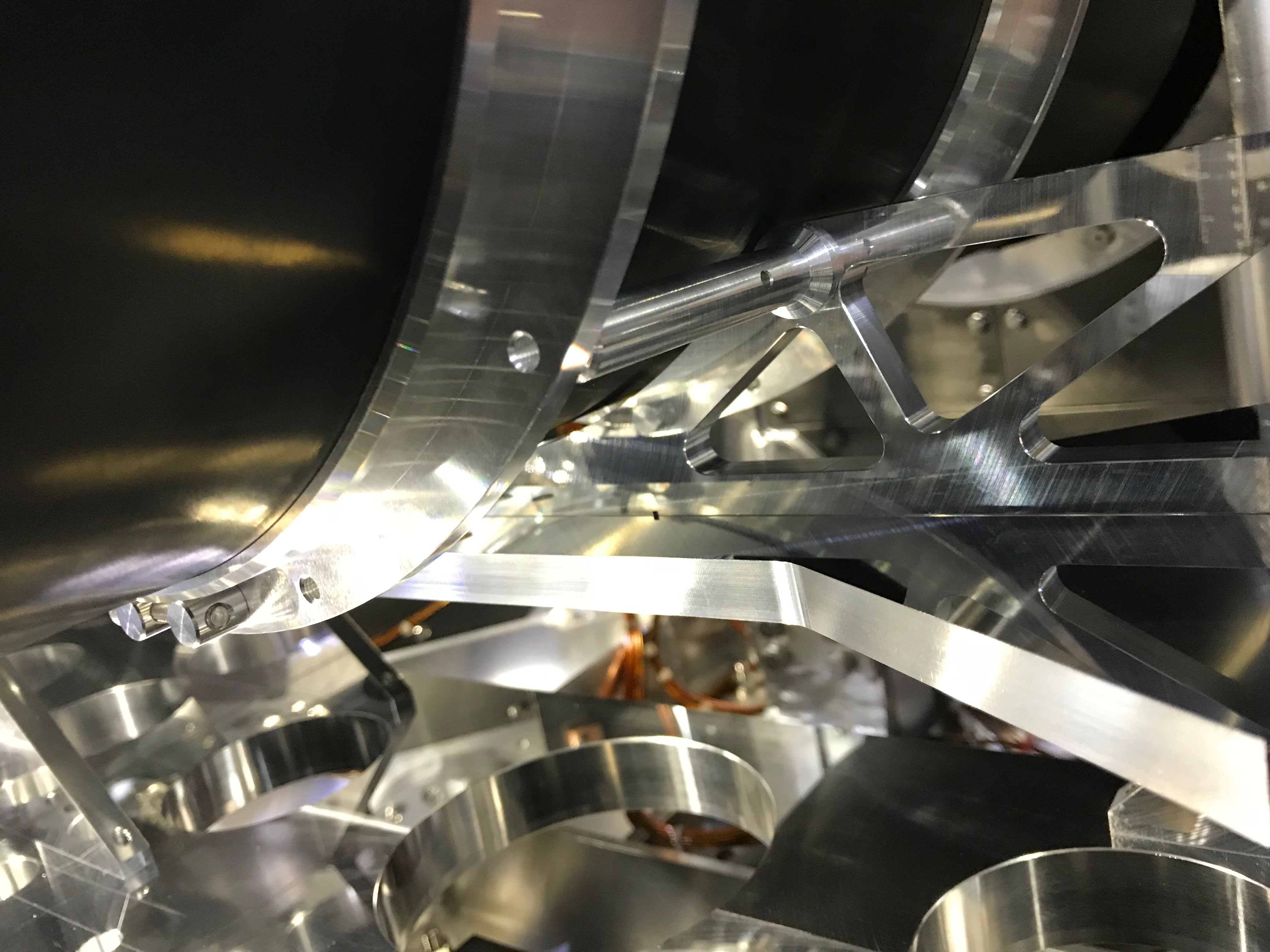
- Looking at the top and bottom gaps between the suspended WAB and the EQ-stop arch structures, this is consistent (Fig 12 and 13); the upper gap seemed wider than the lower (not sure the exact amount).
Need to attach again the magnet dampers (Fig 14).
Note: It would be nice to detach the magnet dampers from the first before the transportation and bring them independently.


