This is report of last week measurement. Sorry for being late.
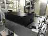
1. Chassis around high power laser output.
We built the chassis around output of fiber amplifier and FI after it.
(It was cool. If we print a KAGRA logo on it, it'll be nicer, I guess...)
2. Detail measurement about beam jitter and intensity noise.
To examine the beam jitter and its effect on the intensity noise of tranmitted light after PMC,
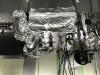
we put two QPDs before and after the position that has the same distance from the laser as beam waist of PMC eigenmode("beam waist of virtual PMC" in the attached picture). Two QPDs were located at symmetrical positions with respect to this virtual PMC.
From these QPD's signals, we can calculate all degrees of freedom about beam jitter.
Vertical (or horizontal) transverse motion can be obtained as common mode of QPD1's pit (or yaw) and QPD2's pit (or yaw).
Vertical (or horizontal) angular motion about the PMC beam waist as differential mode of QPD1's pit (or yaw) and QPD2's pit (or yaw).
We measured beam jitter and intensity noise after PMC under different conditions.
condition 1; All air-conditionings (KOACH and temperature control system) were turned off.
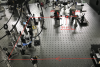
condition 2; A part of main path was covered with aluminum foil (see the attached picture.) with all air-conditionings on.
condition 3; With main path uncovered and all air-conditionings on.
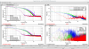
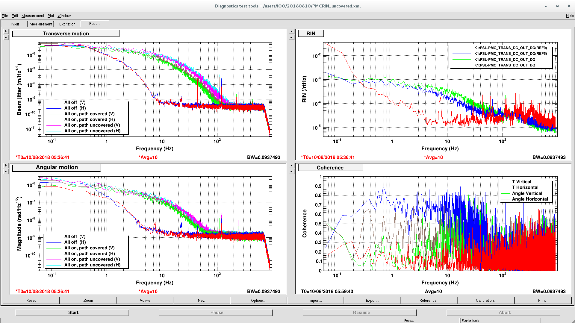
Screenshot of results is attached.
Each degree of freedom is plotted at upper and lower left.
Red and blue lines with legend "All off" are data under condition 1.
Green and brown lines with legend "All on, path covered" are data under condition 2.
Pink and sky-blue lines with legend "All on, path uncovered" are data under condition 3.
It is clear from this results that air-conditionings significantly cause beam jitter and we can reduce it by enclosing beam path with something.
RIN under each condition is plotted at upper right.
Red is data under condition 1, blue under condition 2 and green under condition 3.
We can say that beam jitter were converted to intensity noise and cover reducing beam jitter is effective to lower the intensity noise.
Plot at lower right is coherence between beam jitter and intensity noise under condition 3.
The reason why degrees of freedom about vertical direction showed little coherence with intensity noise may be just because input beam and PMC were well aligned about vertical direction and transmittance intensity responded to beam jitter about the direction mainly in second order.
We concluded that we need to think of some measure about beam jitter caused by air-conditionings in order to reduce intensity noise.