Akutsu-san, Simon
Alignment
(see also the attached pictures from the memobook)
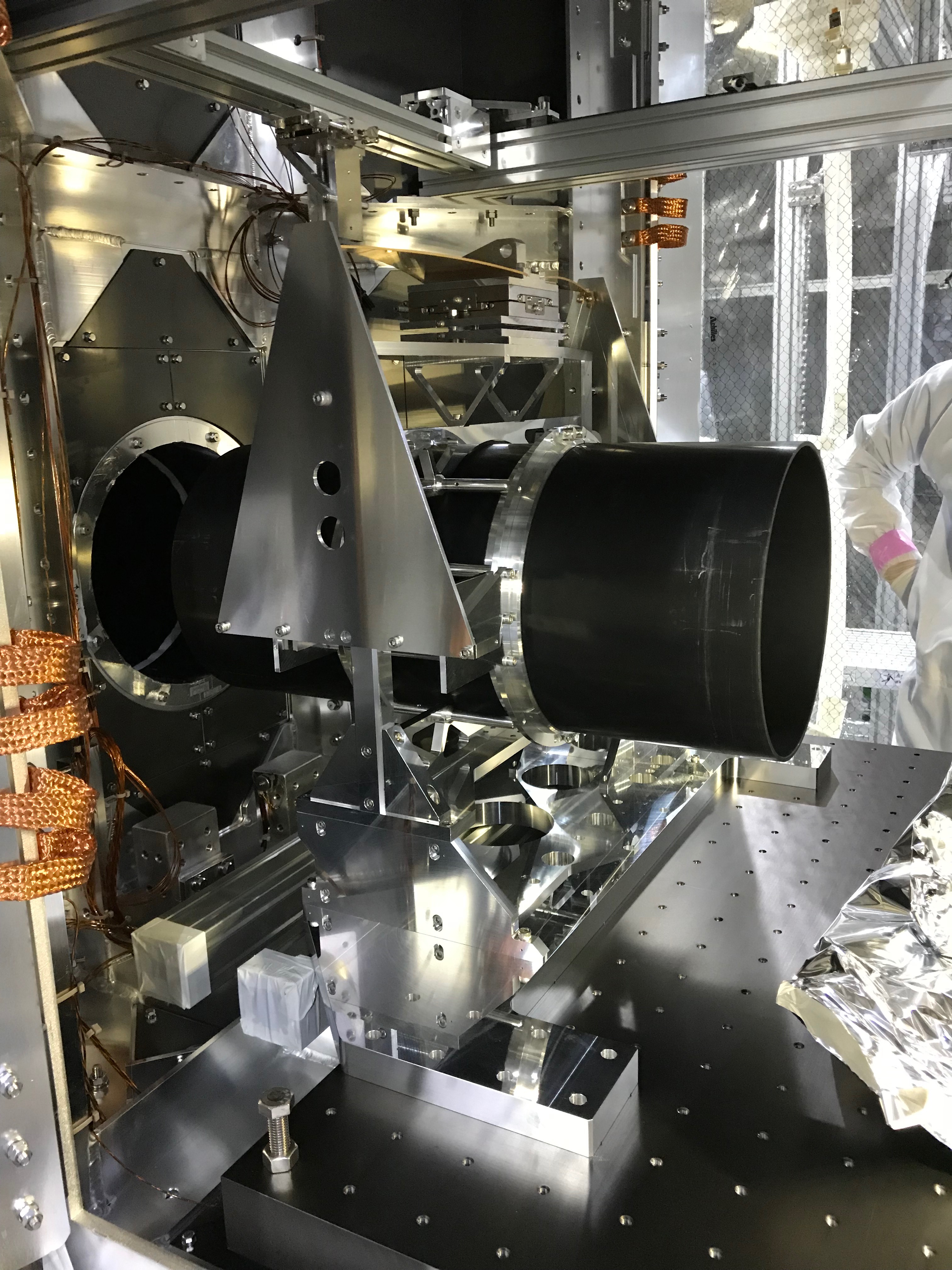
- We moved the WAB back in its nominal position fixed on the optical table to do the alignment. After that, we removed the baffle- and the wire-protectors.
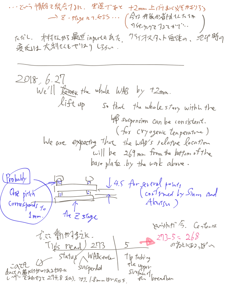
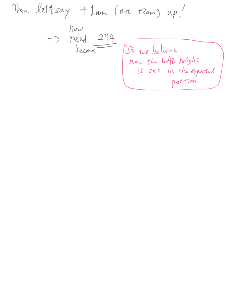
- Then we did alignment measurements on the horizontal and vertical position of the WAB inside the cryostat. They show that in its initial position the center of the baffle has 268mm height from the optical table. To put it into room-temperature nominal position, we lifted the baffle today by 1mm to 269mm.
- There might be a very small pitch offset left but it is hard to measure actually.
-
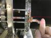
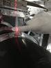
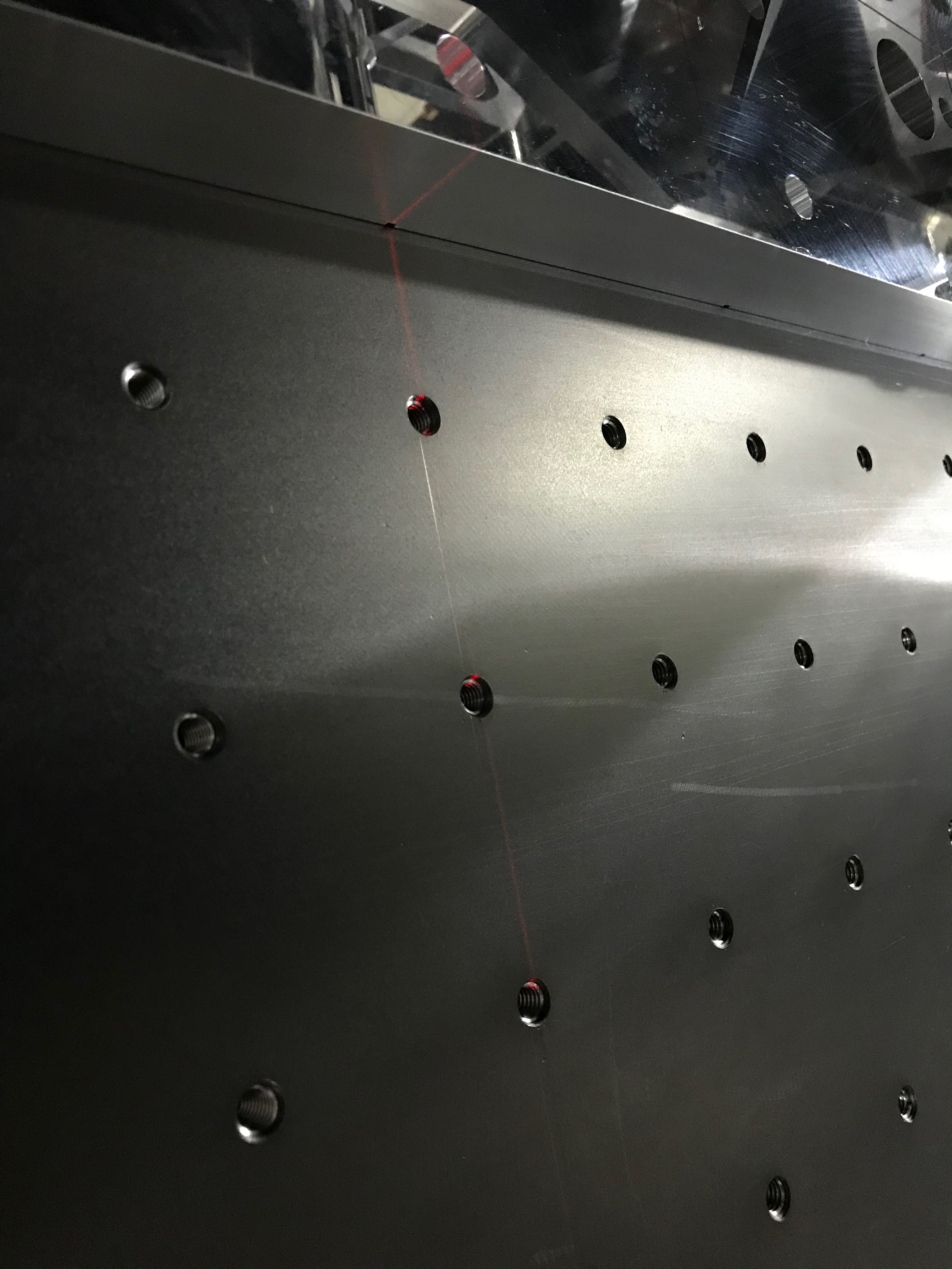
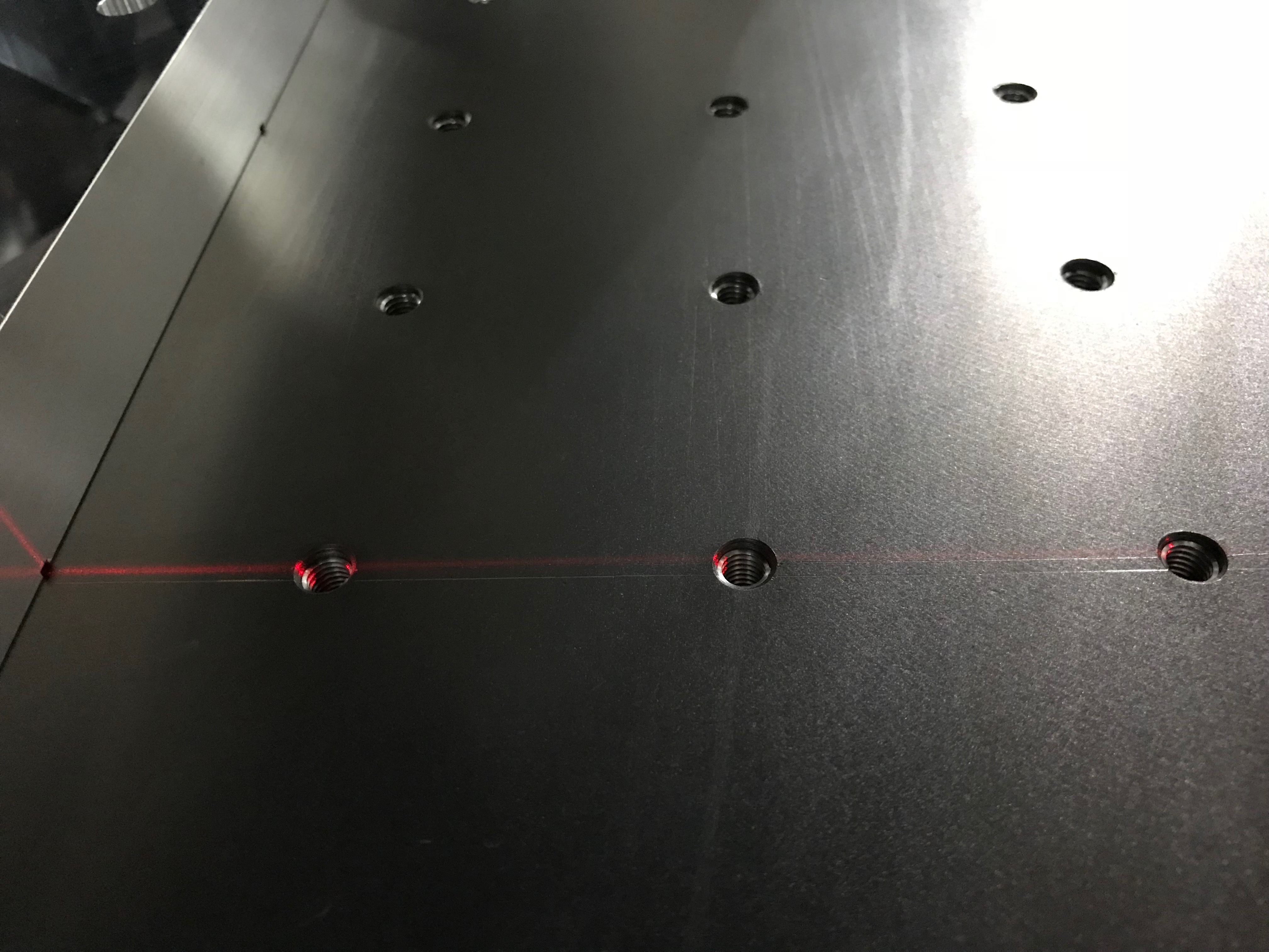
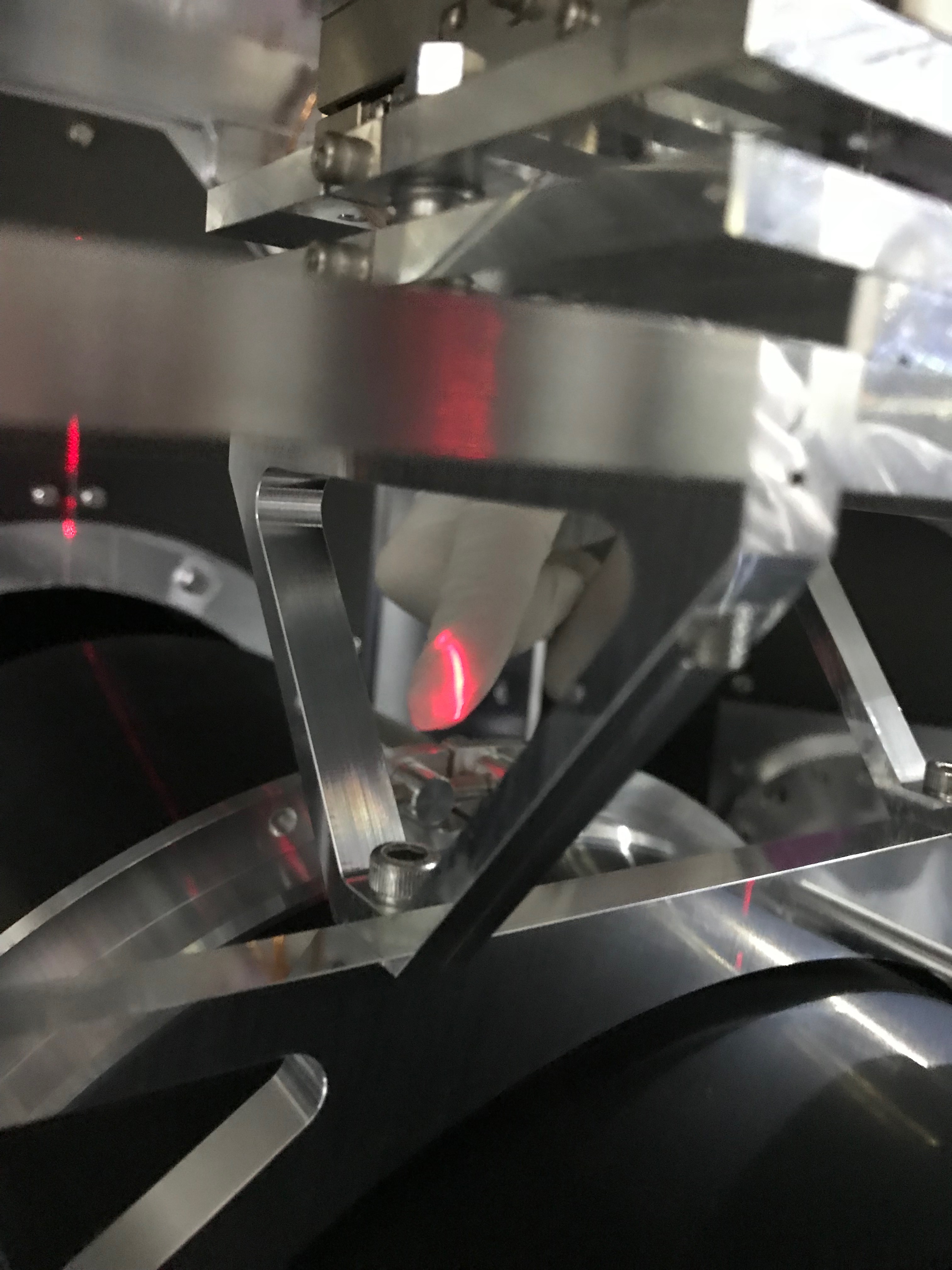
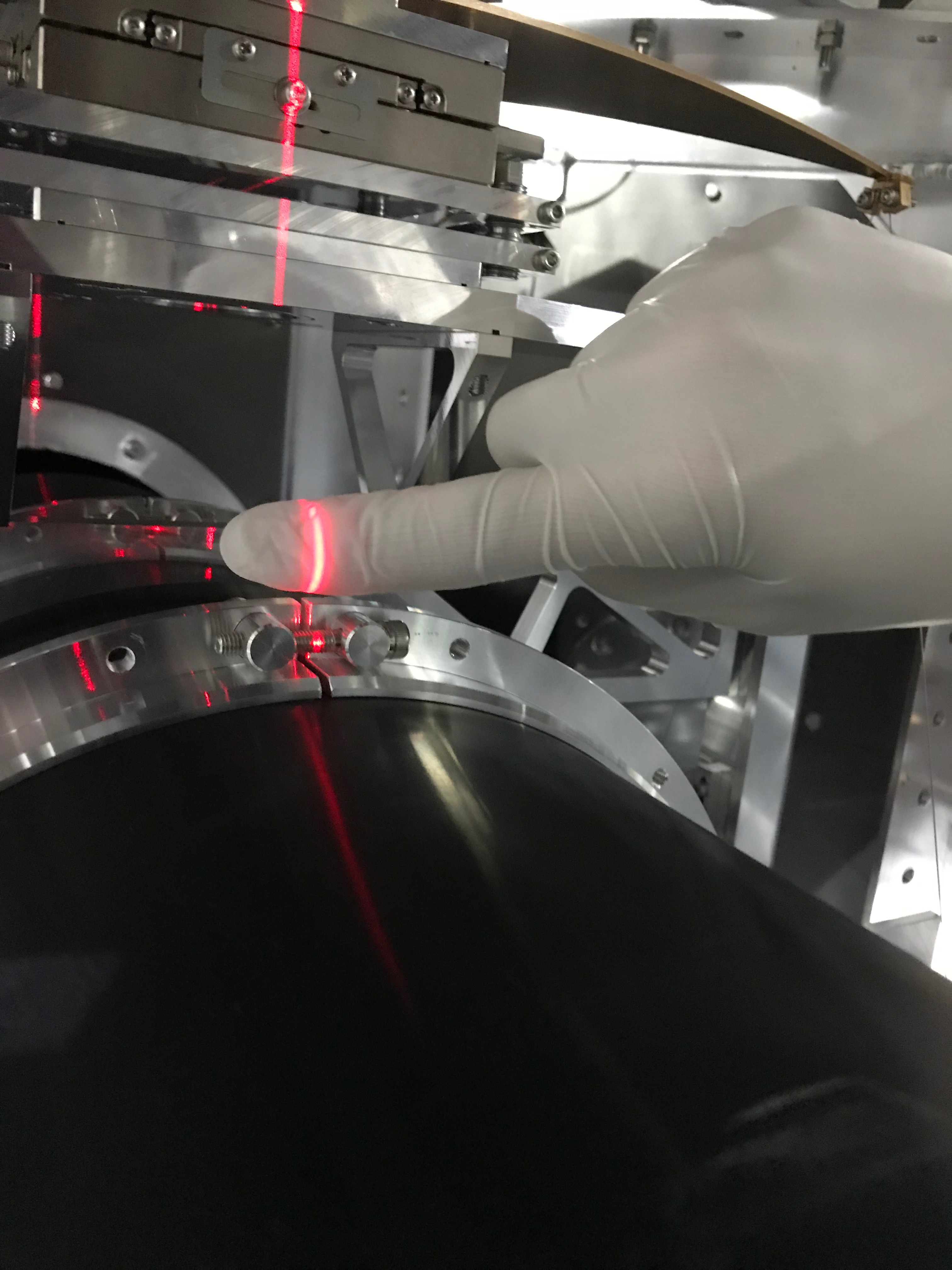
For the yaw alignment, we needed a reference line. However, there are basically two lines on the optical table that could serve as that (see picture)
- A careful adjustment of the laser leveler to both of them showed us that the one on the -Y side seems to be the centerline of the optical table
- The on the +Y side, however, is corresponding to some indication marks on the duct opening. Maybe, this is the main-beam line(?)
- We choose the table's centerline for being a reference to align the yaw and the horizontal position of the WAB!
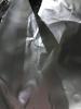
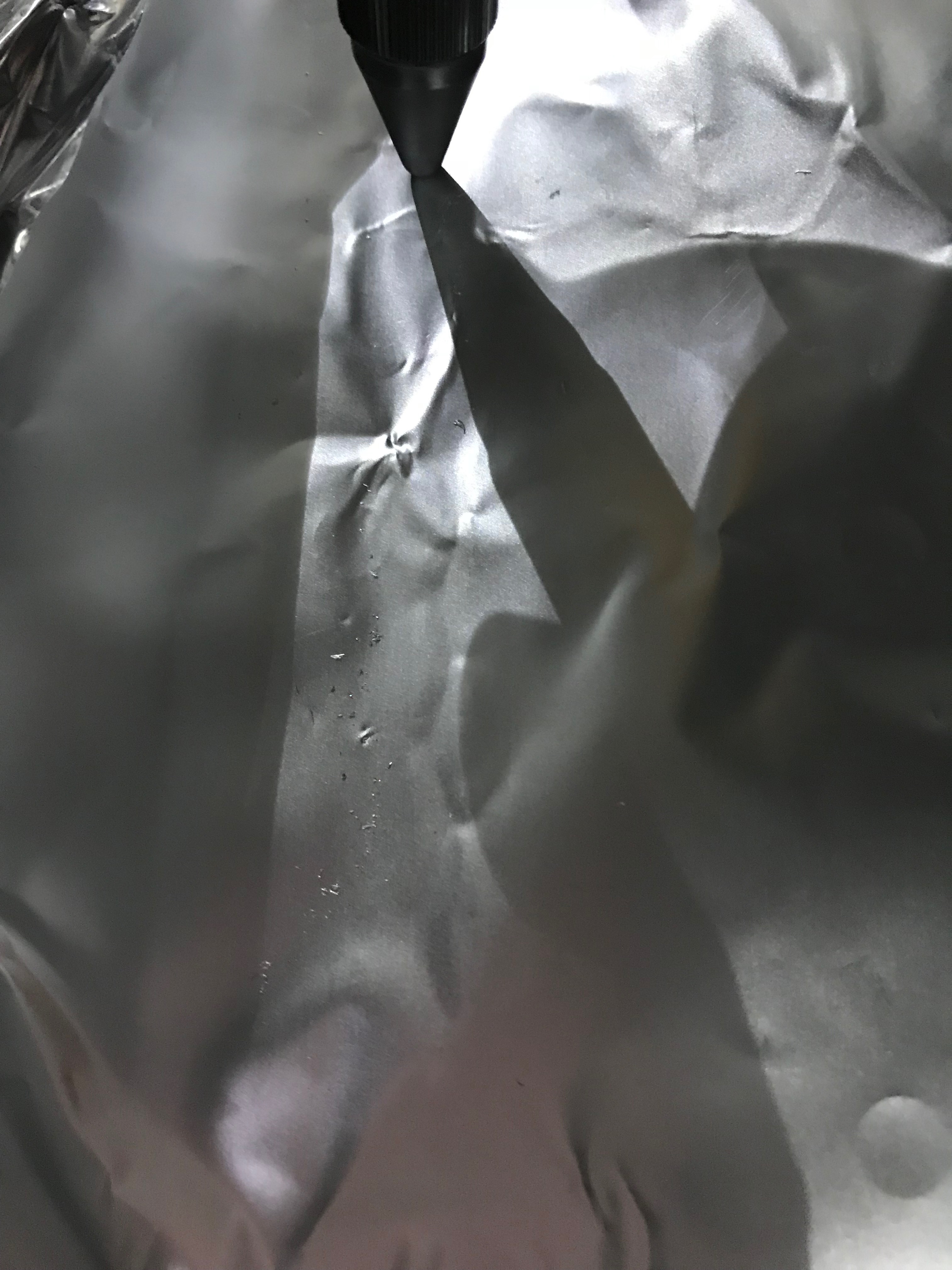
- Note: to have the laser-leveler in a good position (illuminating the upper side of the baffle and the lines on the table), we put a plastic-box covered in Aluminum-foil on the optical table and shifted it backward (with support of a Misumi bar). Then, the laser-leveler just needs to be put on top of it.
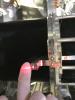
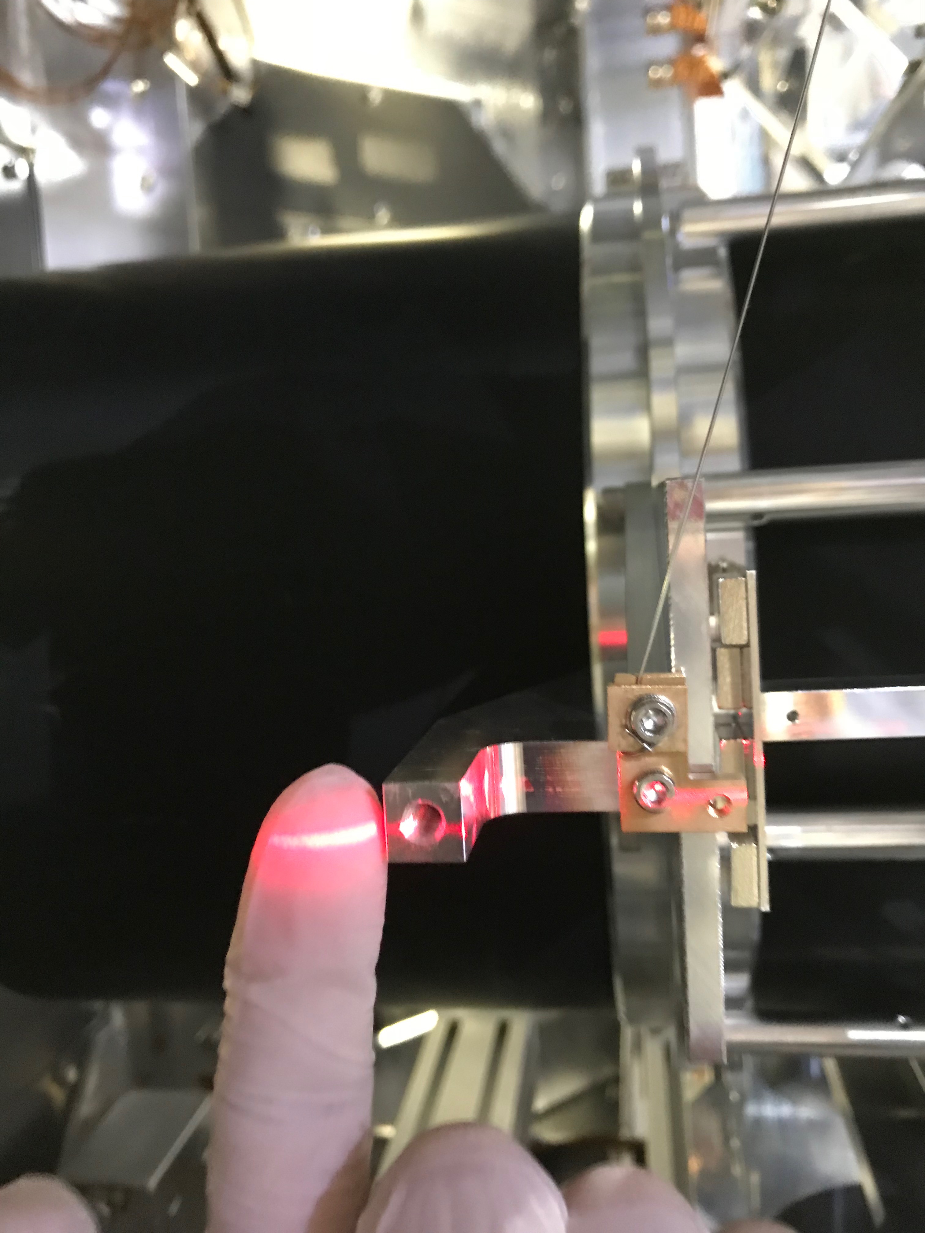
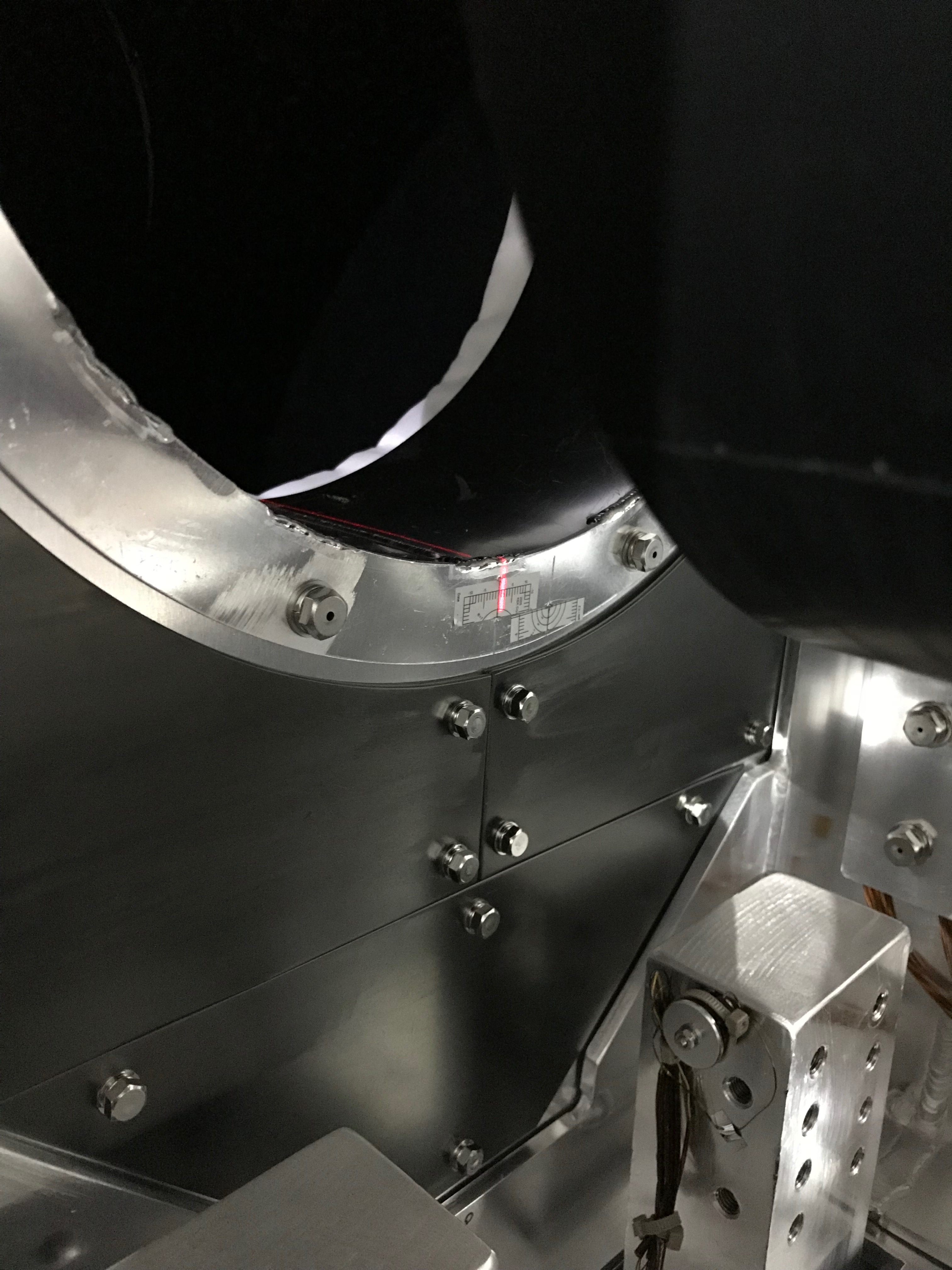
- In yaw, we found no offset within an accuracy of 0.67° (defined by the gap of the flanges which was used for the alignment, see pictures)
Put baffle in "saving mode"
Normal procedure (WAB starts in nominal position):
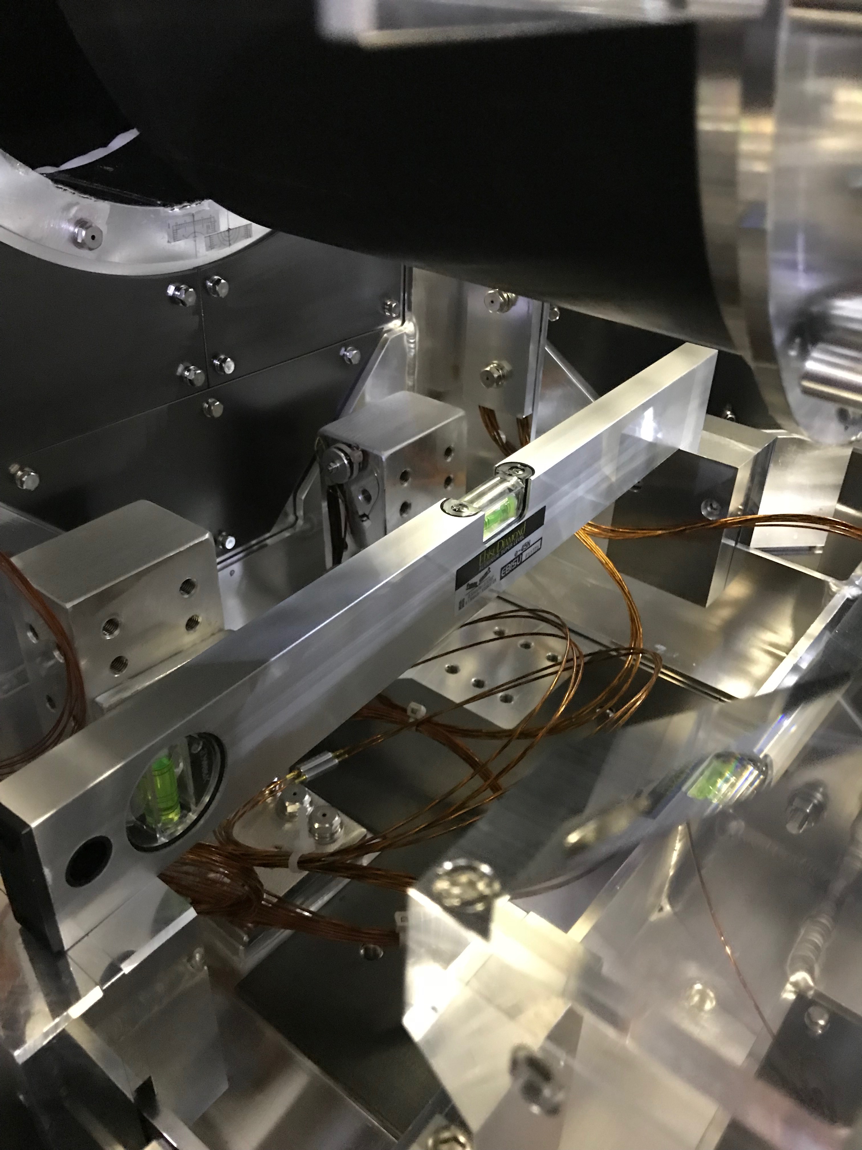
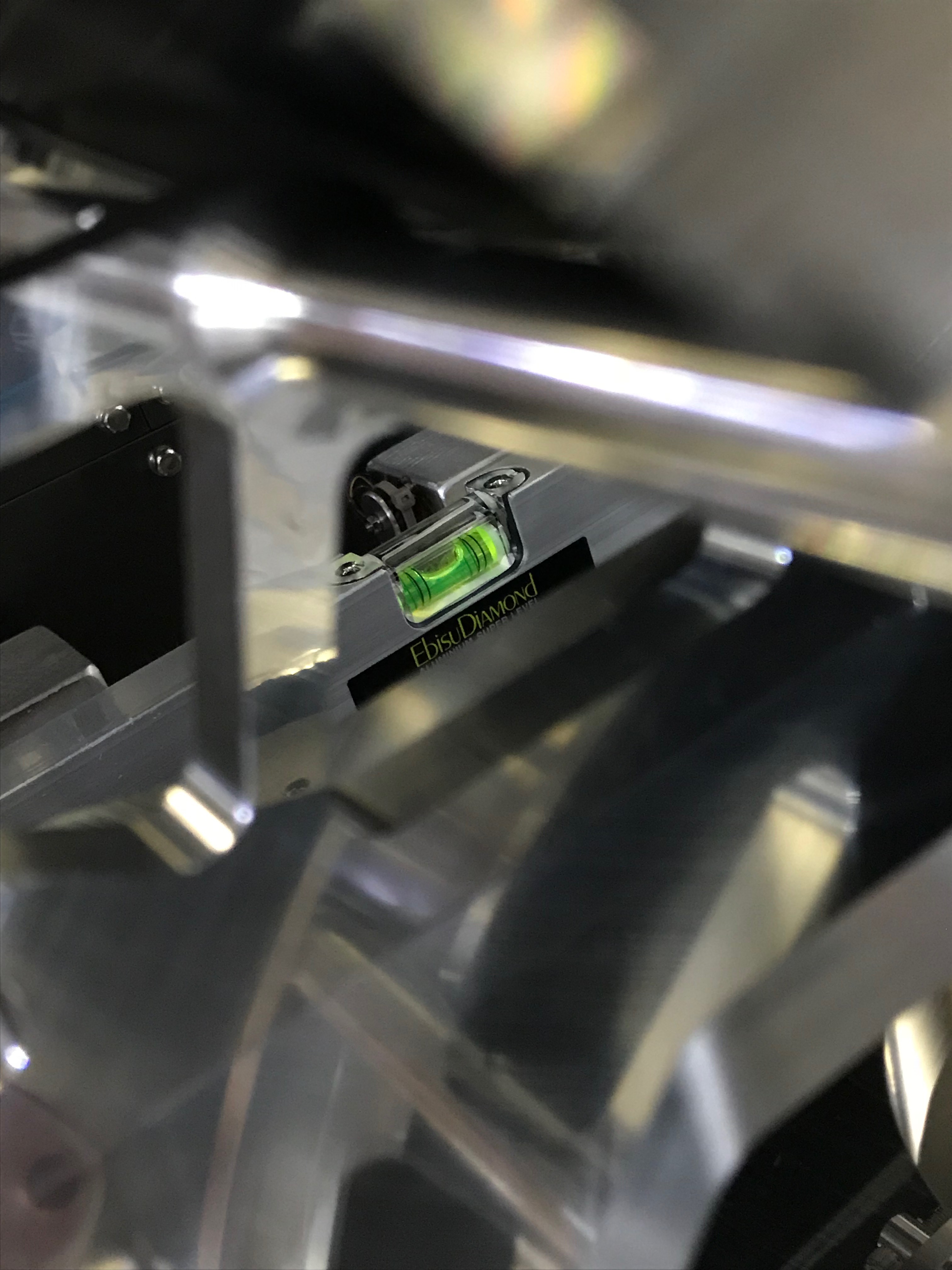
- Adjust the holding blocks to the measured height-difference of cryostat's T-beams on the ground of the optical table
- Place the holding blocks on the T-beams (4 points)
- Hook the WAB on the traverser (no lifting!)
- Remove the screws, holding the WAB onto the optical table (there might be some lifting necessary, depending on how smooth the screws can be removed)
- Lift-up the WAB so that it can pass the fixing-screws of the optical-table. Put stoppers on the traverser's slider when lifting.
- Slide the WAB toward the duct but stop when just passed the optical-table's screws (again, put stoppers right in place so that the baffle does not hit the walls)
- Lower-down the WAB so that it can enter the duct (Put again stoppers on both side of the slider when lowering)
- Slide it inside the duct until the end of the slider is reached (there is a stopper anyways, so don't worry)
- Lower-down the WAB onto the blocks (put stoppers so that the slider cannot move back)
When sliding the WAB into the duct, we need to take care that it is not yawing too much. Otherwise, the baffle may hit the duct and will be scratched.
Issues:
-
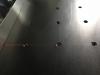
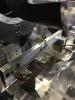
Even though the blocks were adjusted with almost perfect planarity (as can be seen in the attached pictures), we discovered that placing the WAB eventually will leave some blocks untouched...
- -> We are still unsure why but probably, the two screw-heads, on which the block is residing, have not a stable stand (or equal height) enough and cause one or two of the blocks to be obliqued when the WAB is settling down. Thus, the whole WAB may become obliqued and there will be a gap to other blocks.
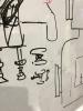
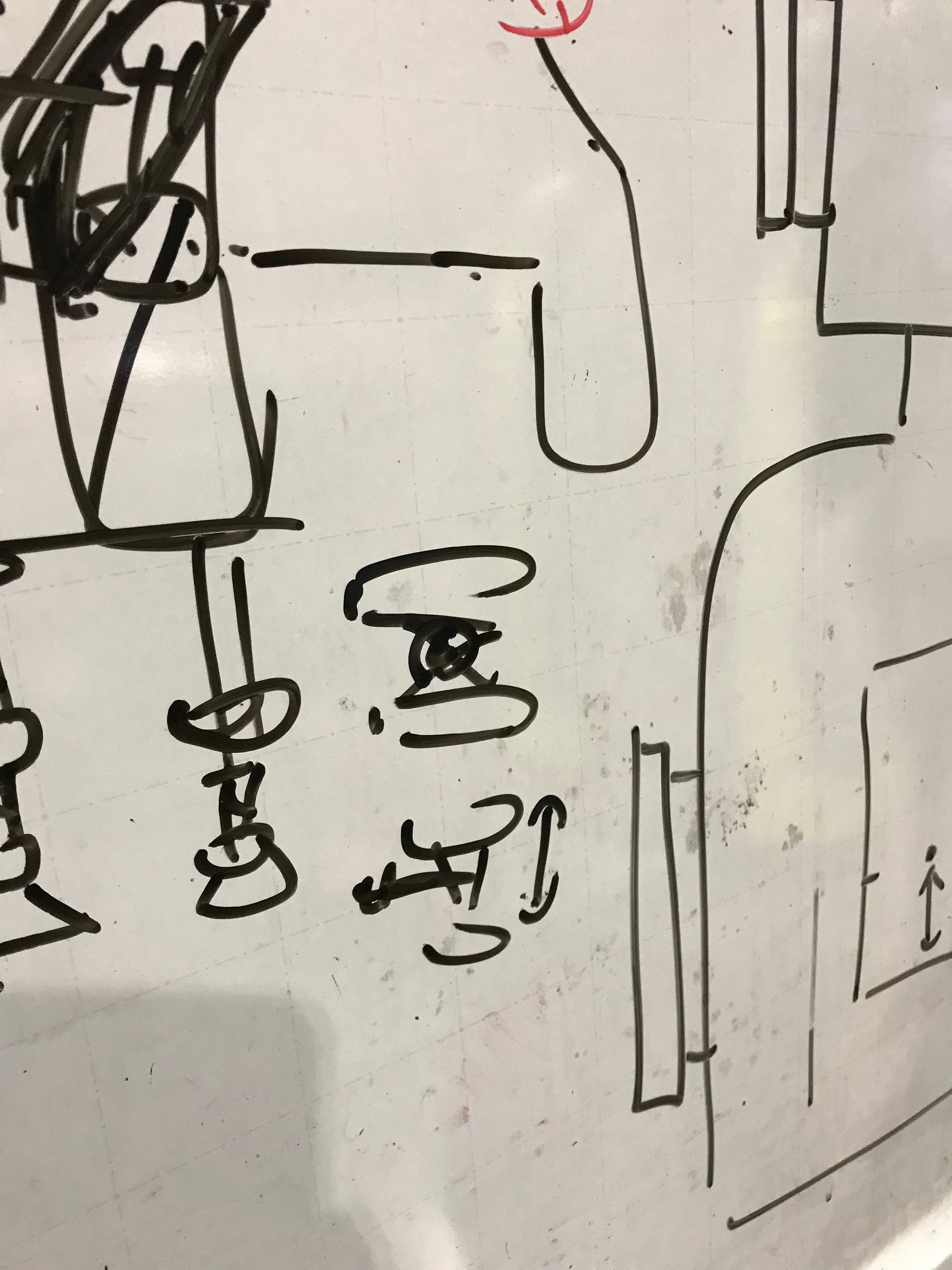
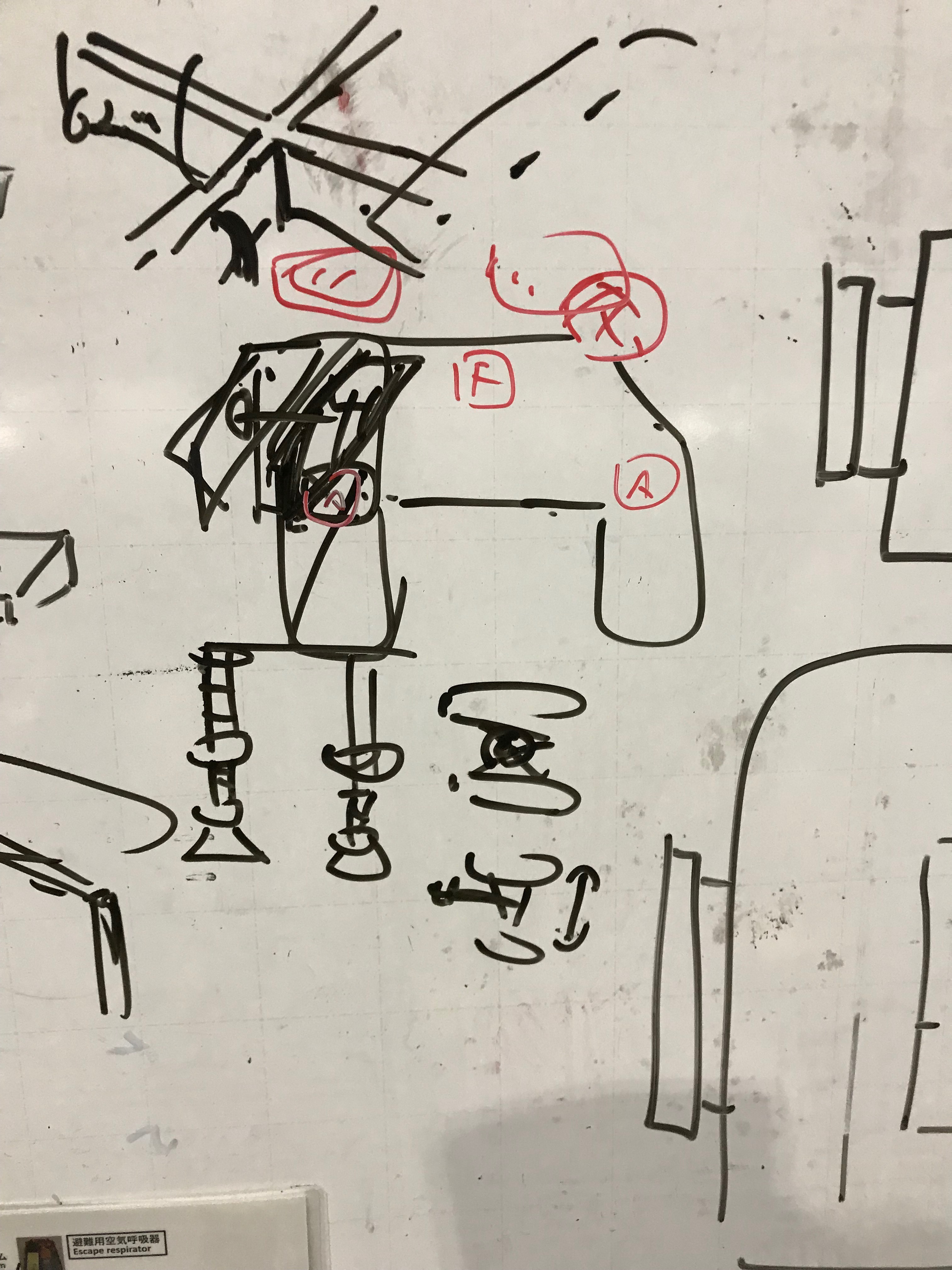
- To overcome this problem, a new design in the future may be necessary
- e.g. put one stand in center toward the duct-side with a fixed height, and two other stands at each side with an adjustable height to stabilize the WAB (see the attached white-board sketches).
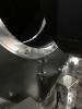
- Although, we did an alignment of the baffle to the (what we think) centerline of the optical table, inserting the baffle into the duct showed that there is less space on the -Y side than on the +Y one. This is not really an issue as long there is at least some space. However, one needs to be careful and observe both sides when inserting!
- Another issue is that by unmounting the baffle protectors, there seems to be a lot of dust being produced (small Aluminum parts). We used sheet of Aluminum foil to catch the dust when we removed the protectors.


