Simon, Ken Tanaka, Akutsu on 22 June 2018
Abstract
We measured several dimensions in the IXC chamber, then brought the whole WAB suspension into the IXC chamber. Also we played around the WAB traverser with the WAB suspension, and finally tentatively locate the WAB suspension in its saving mode.
Measuring dimensinos
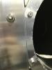
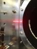
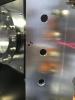
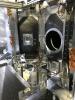
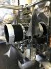
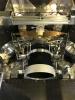
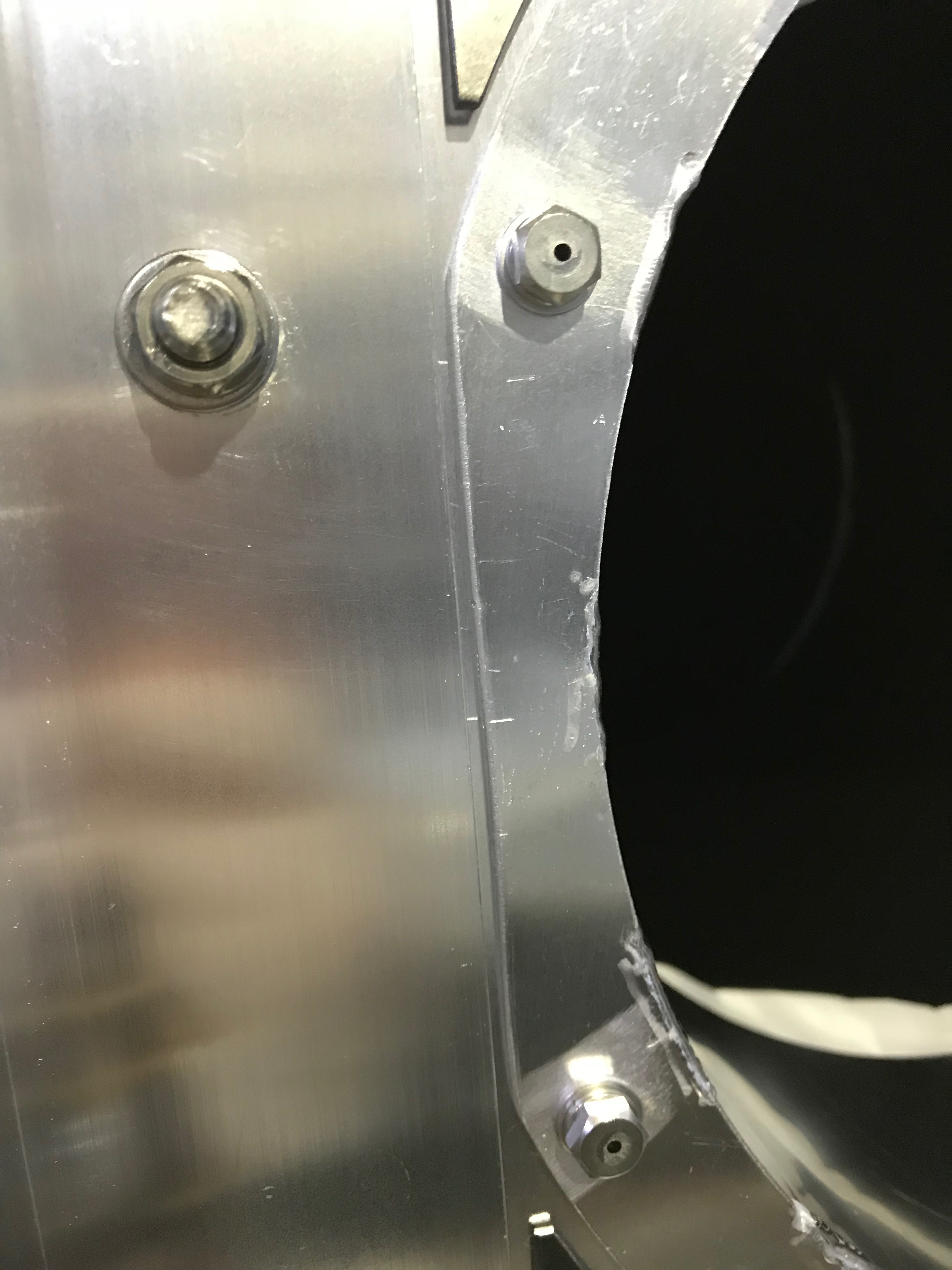
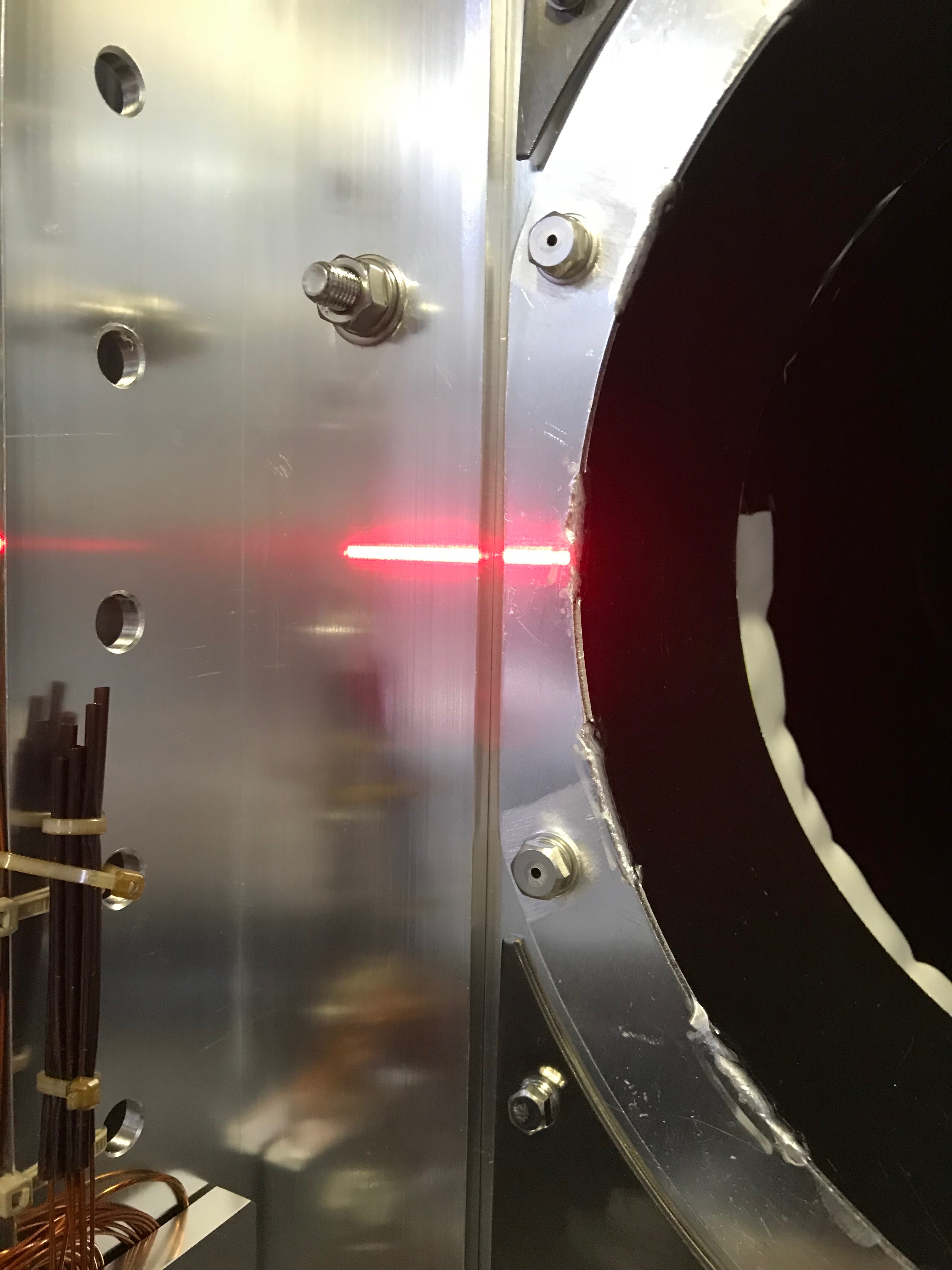
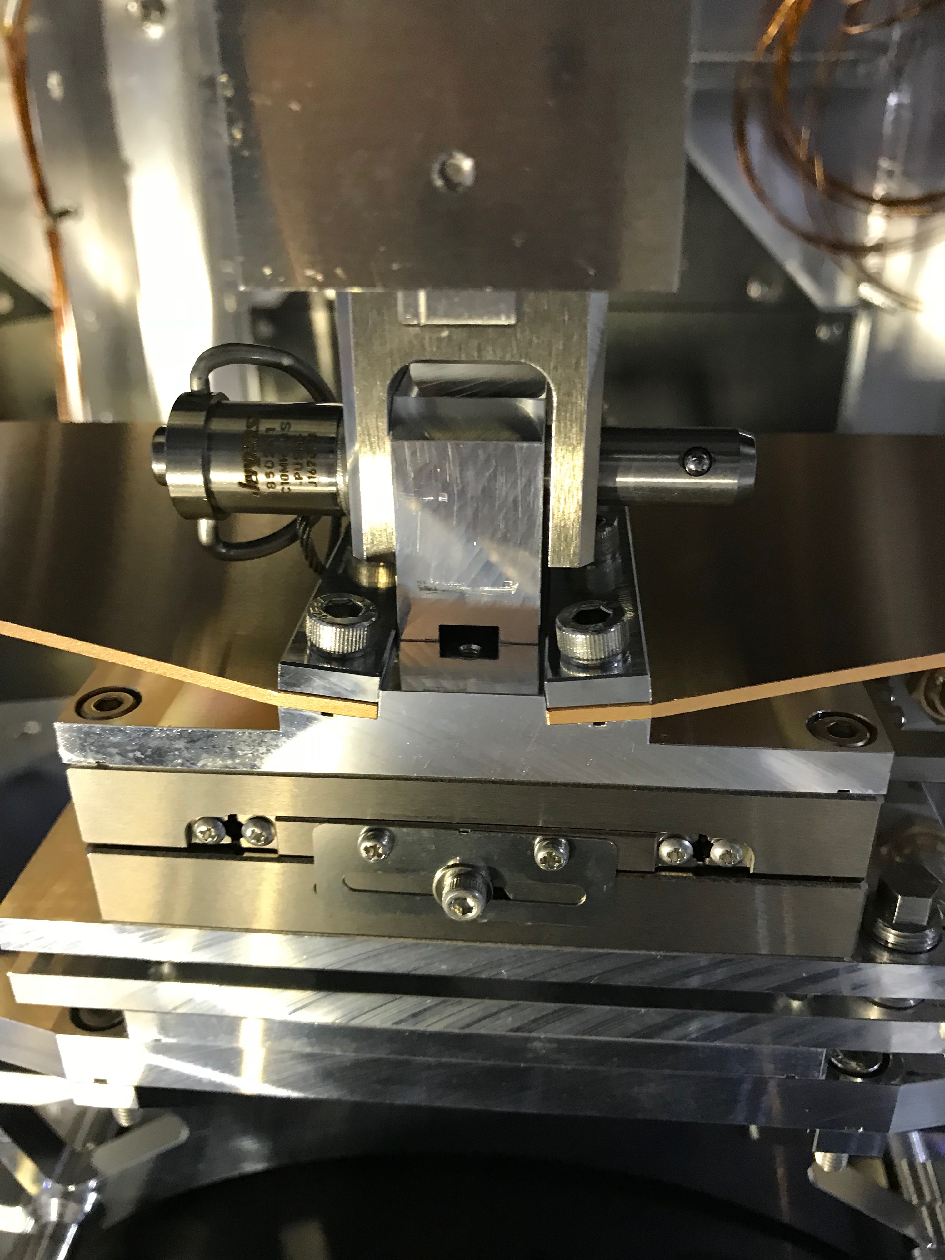
To design or modify the islands that finally supports the WAB suspension in the saving mode, we need to know the differeneces between the 3D model of the chamber and the actual world. From this viewpoint, we did several measurement and finally learned that the height distance from the upper surface of the breadboard lying in the chamber to the duct's center would be as nominal value: 270mm (Figs 1-3).
Bringing the WAB suspension
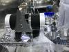
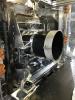
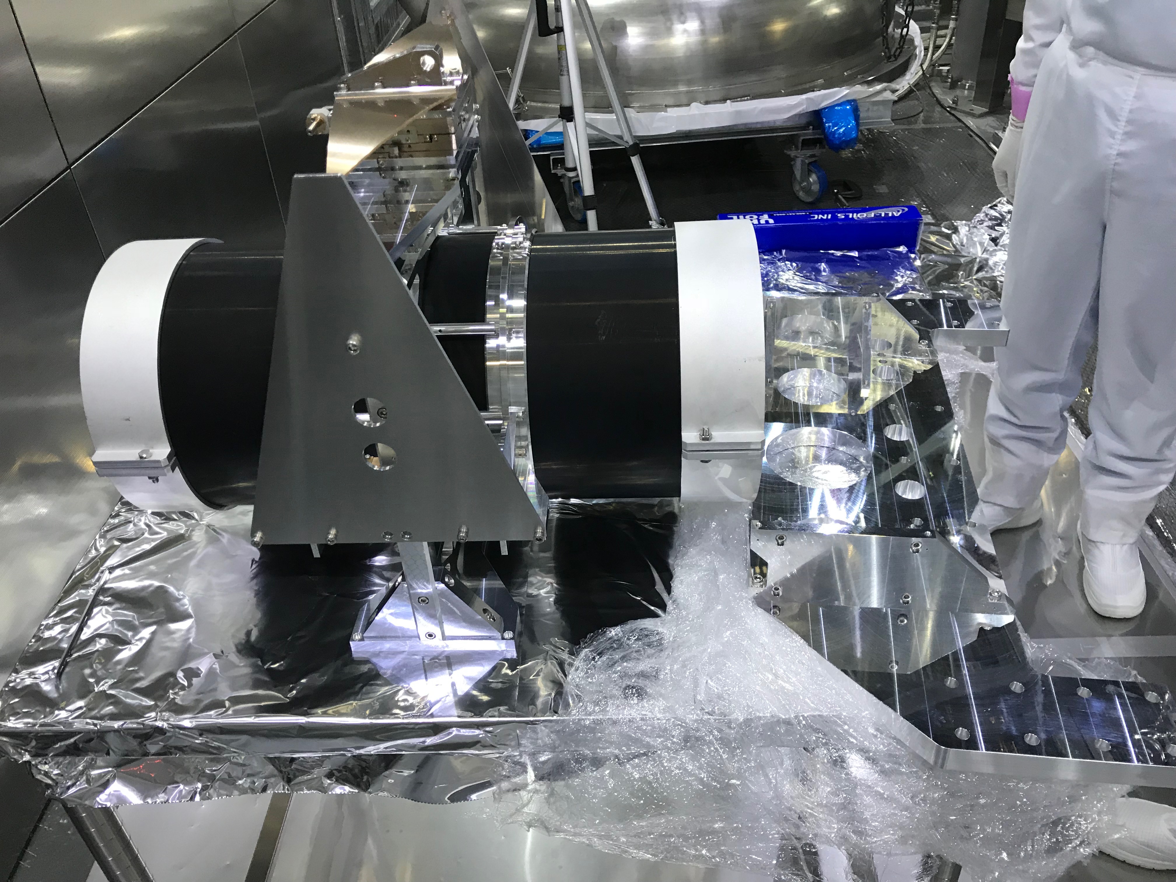
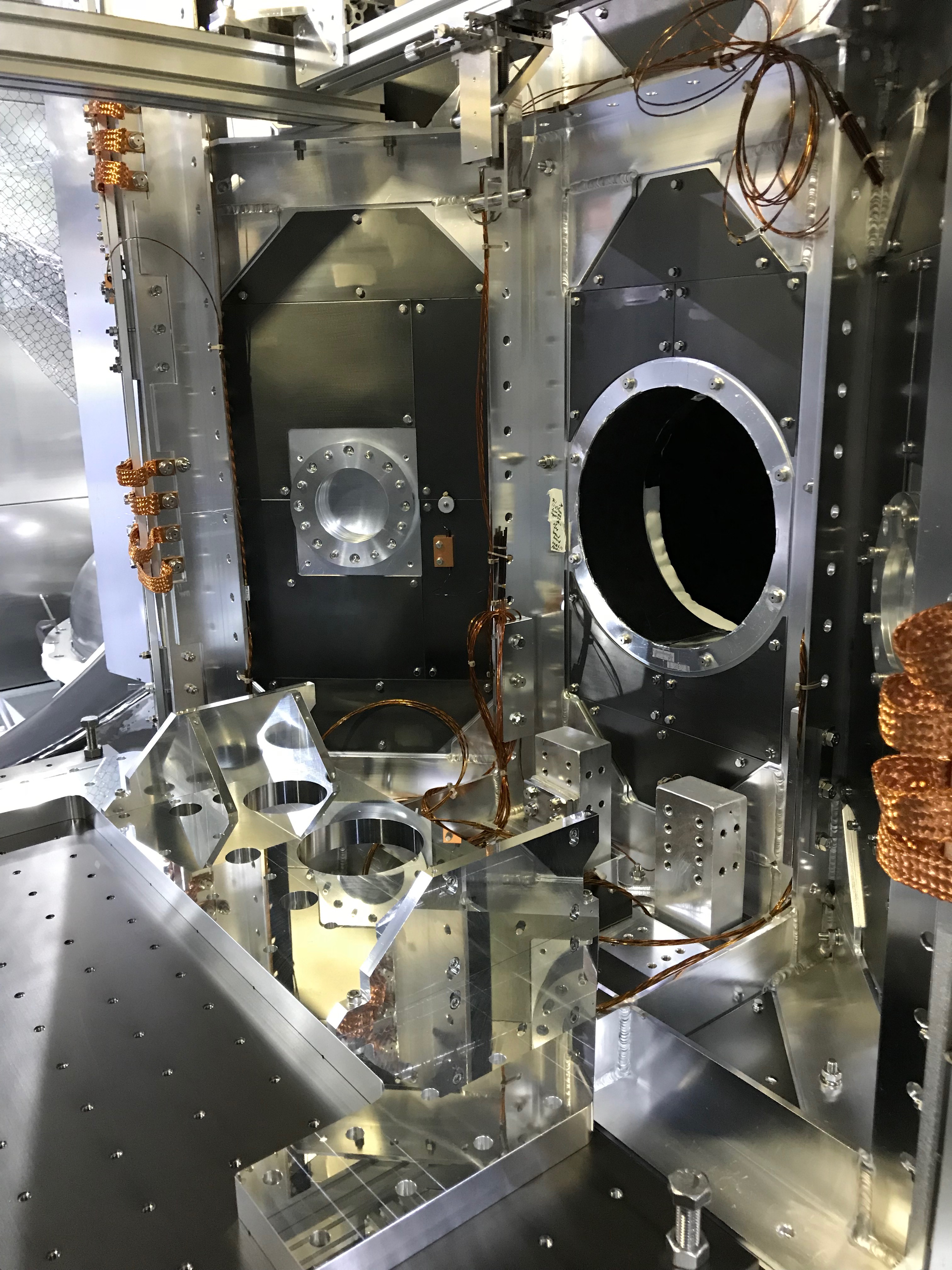
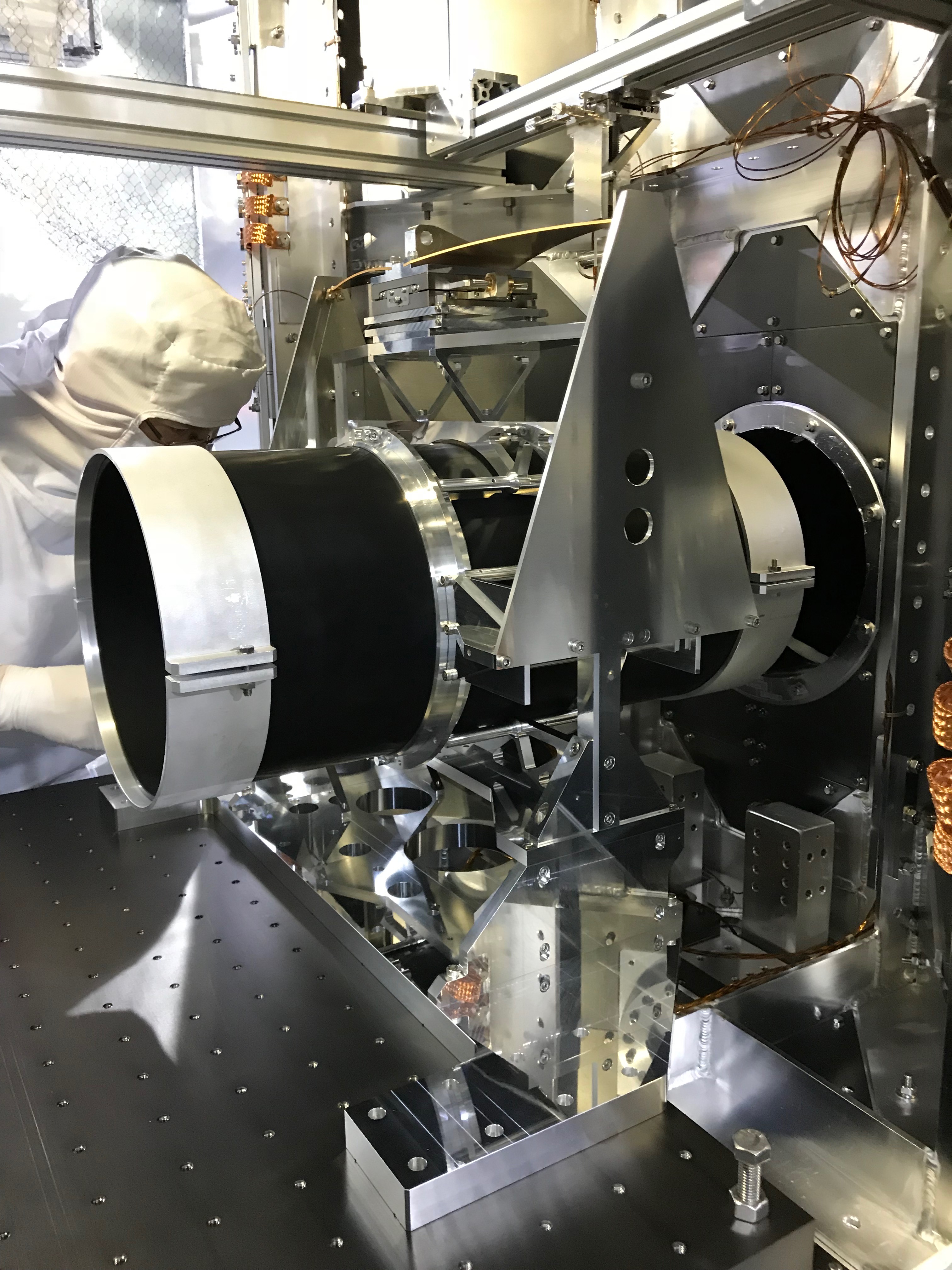
We detached four screws that were fixed the upper and lower half of the WAB suspension on the desk outside of the chamber. The upper half can stand alone on the desk (Fig 4). Then we brought the lower half --- meaning the baseplate plus alpha --- into the chamber and put on the breadboard. The baseplate was tetatively fixed with several screws at its nominal position (Fig 5) so that the WAB traverser can access it from the top. Then the upper half was also brought into the chamber, and put on the lower half, and fixed to it with the screws (Fig 6). The transportations were done by our hands and powers!
Traversing the WAB suspension
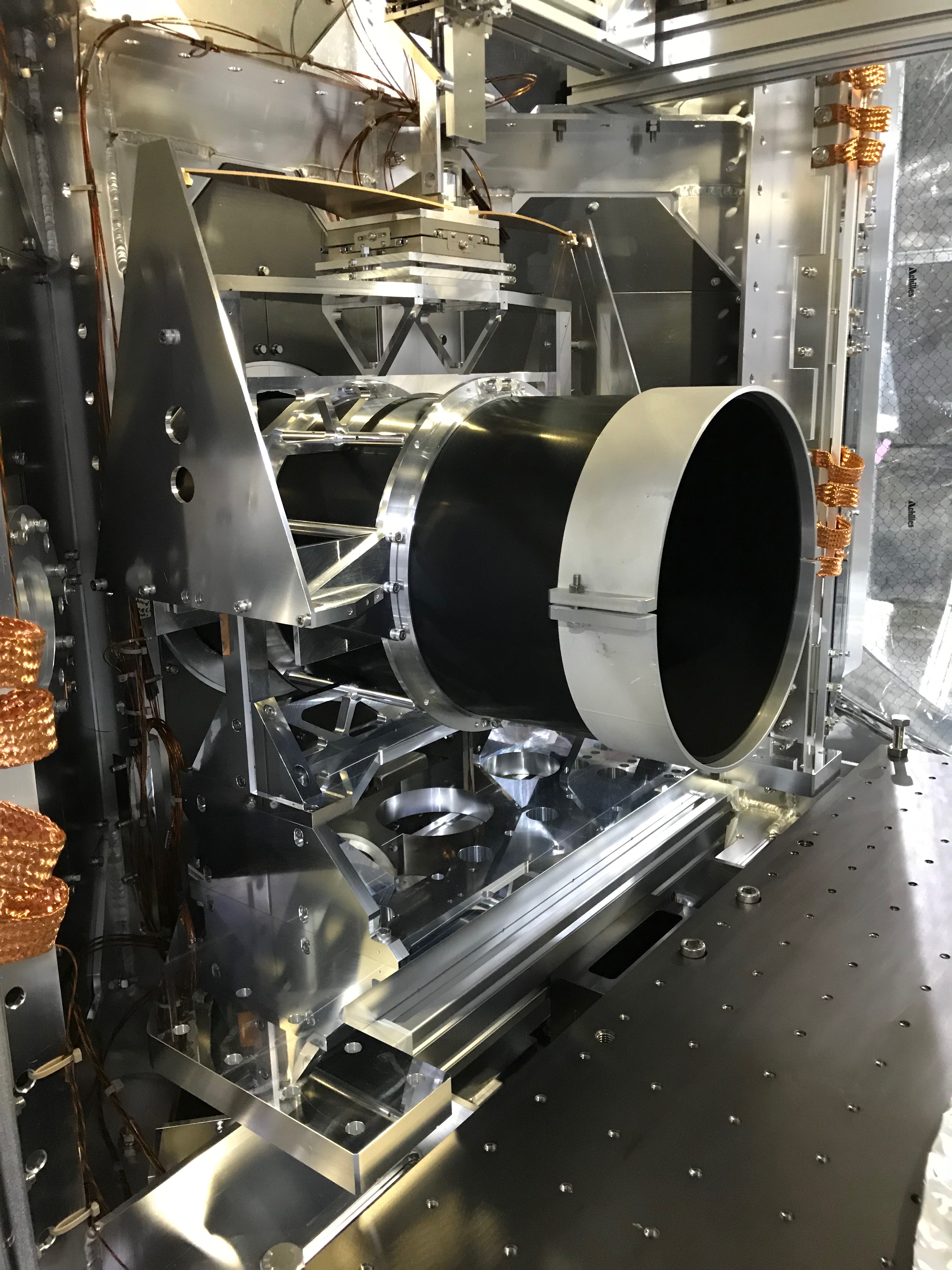
Using the setup of the WAB traverser (see here), we connected the hook to the top of the WAB suspension (Fig 7). Then we removed the screws fixing the base plate to the breadboard while carefully checking the balance of the WAB suspension, as the half footprint of the base plates in its nominal position was out of the breadboard, so it would be more or less unstable. After removing all the screws, we lifted up the suspension carefully to be floated (Fig 8), and tested the traversibility, and found it was very smooth; too smooth so we need to put stoppers on the both beams.
By lying two misumi bars, which had been used in the IYC test at that time and were used here tentatively, the WAB suspension was brought to its saving mode postision (Fig 9). Before inserting the half of the WAB into the duct, don't forget to remove the protector attached to the edge of the WAB. The protector on the other side should be remained until the installation phase.
