Ikenoue, L. Shimizu, Simon, Yokozawa, and Akutsu
Abstract
Inserted the NAB suspension assembly to the inner tower of IXA.
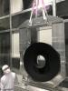
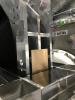
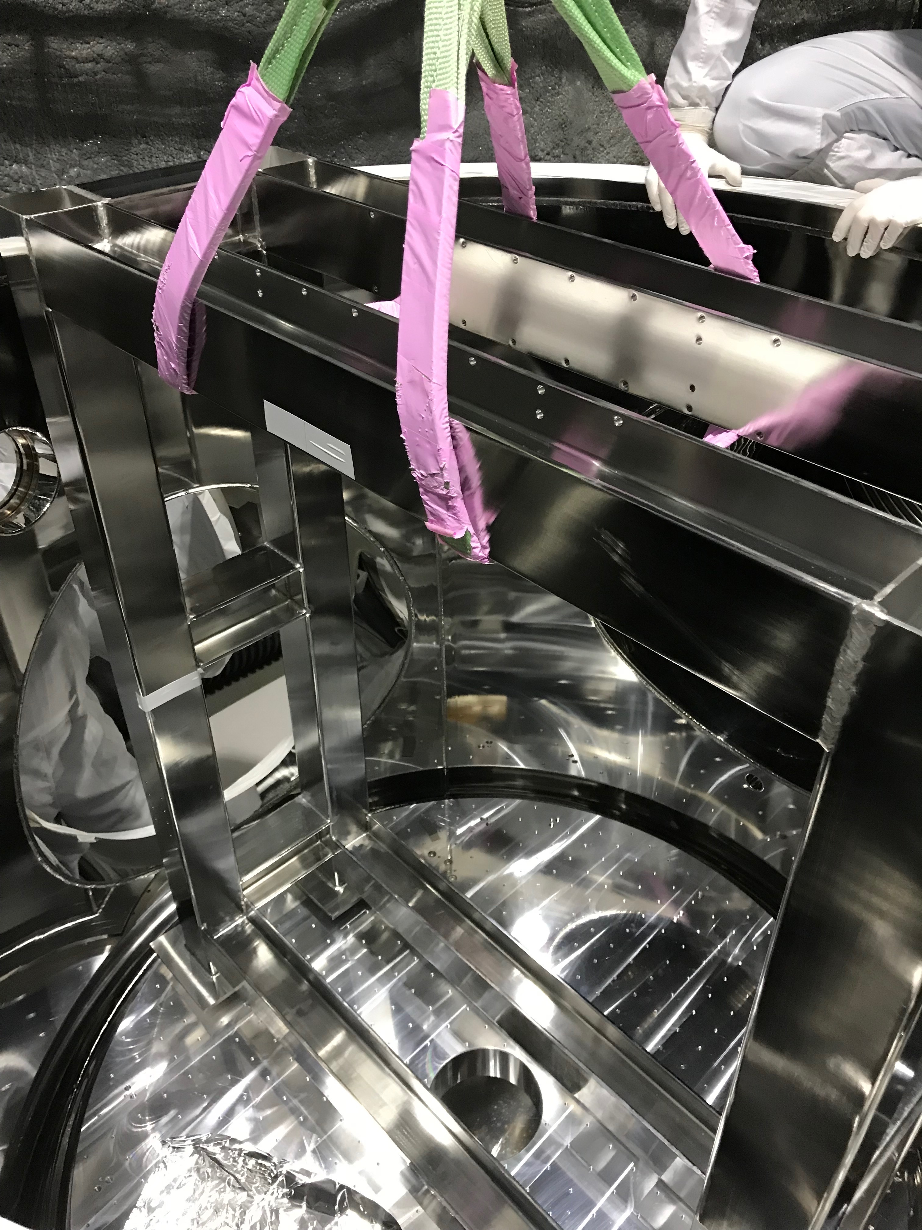
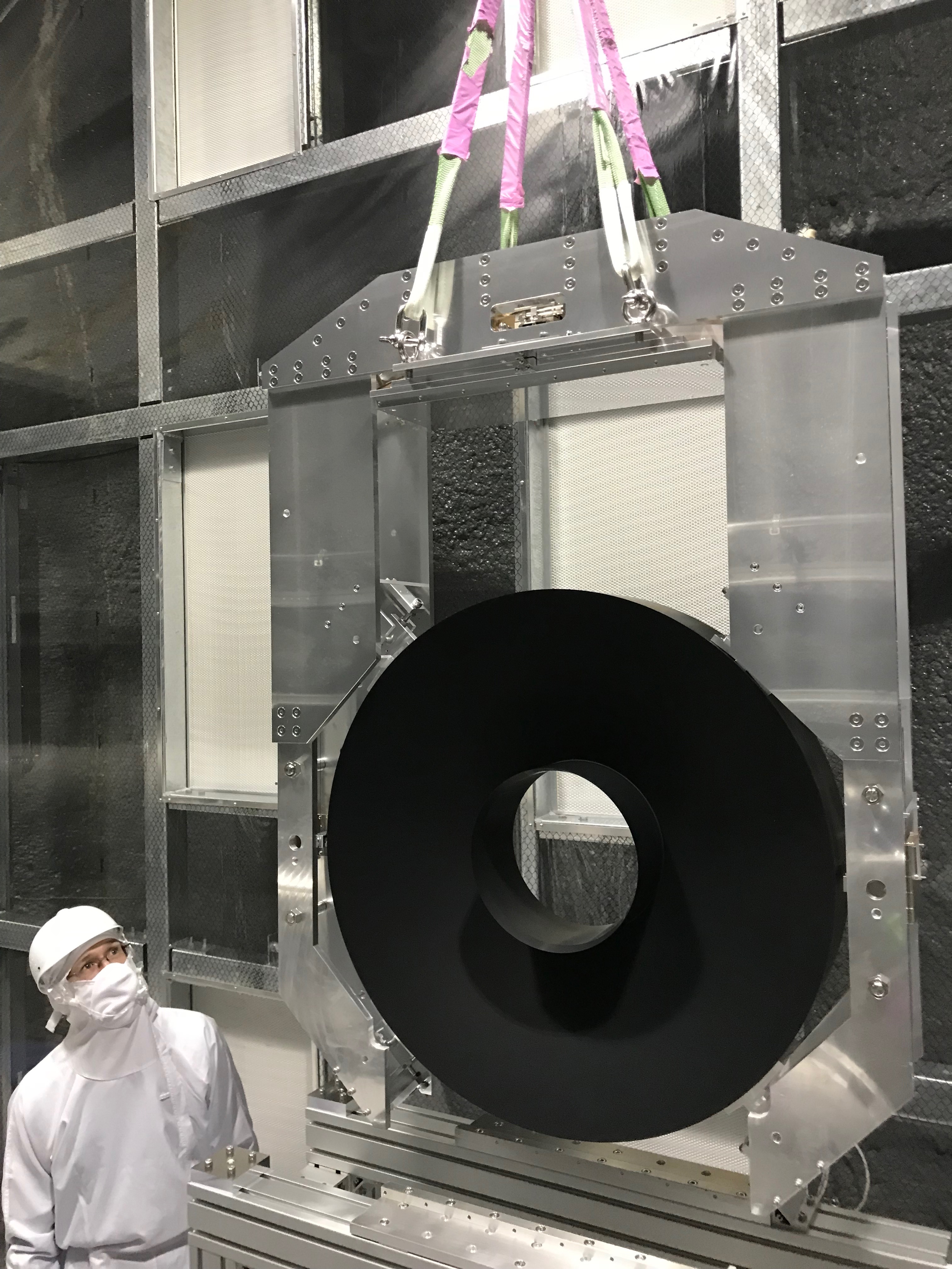
Detaching the inner tower
Because the crane above IXA cannot move in transverse, it is natural to carry out the assembly work just under the crane-movable line. We first detached the inner tower (yagura) from IXA (Fig 1), and put on the floor outside of the chamber. This was because it was difficult to access around the inner tower when it was at the center of the chamber. During the moving the inner tower in the transversal direction (-Y direction), the inner tower got dancing due to the rough move of the crane, but this was unavoidable, as the crane itself was violent move.
To stabilize the alignment of the inner tower, some shims were inserted underneath one of the four legs. The tilt was checked by bubble levers and ... probably it was ok.
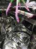
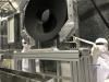
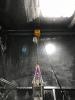
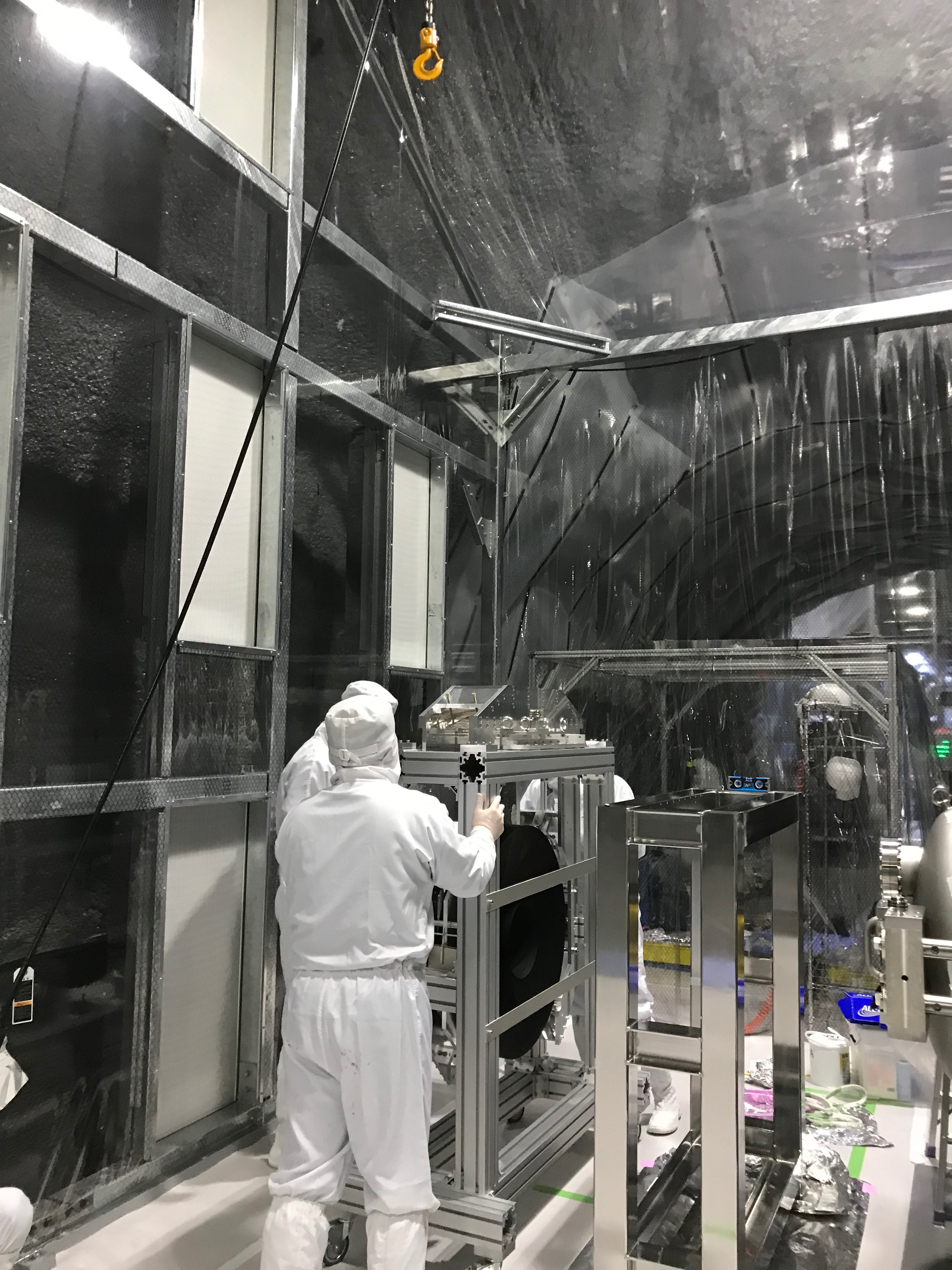
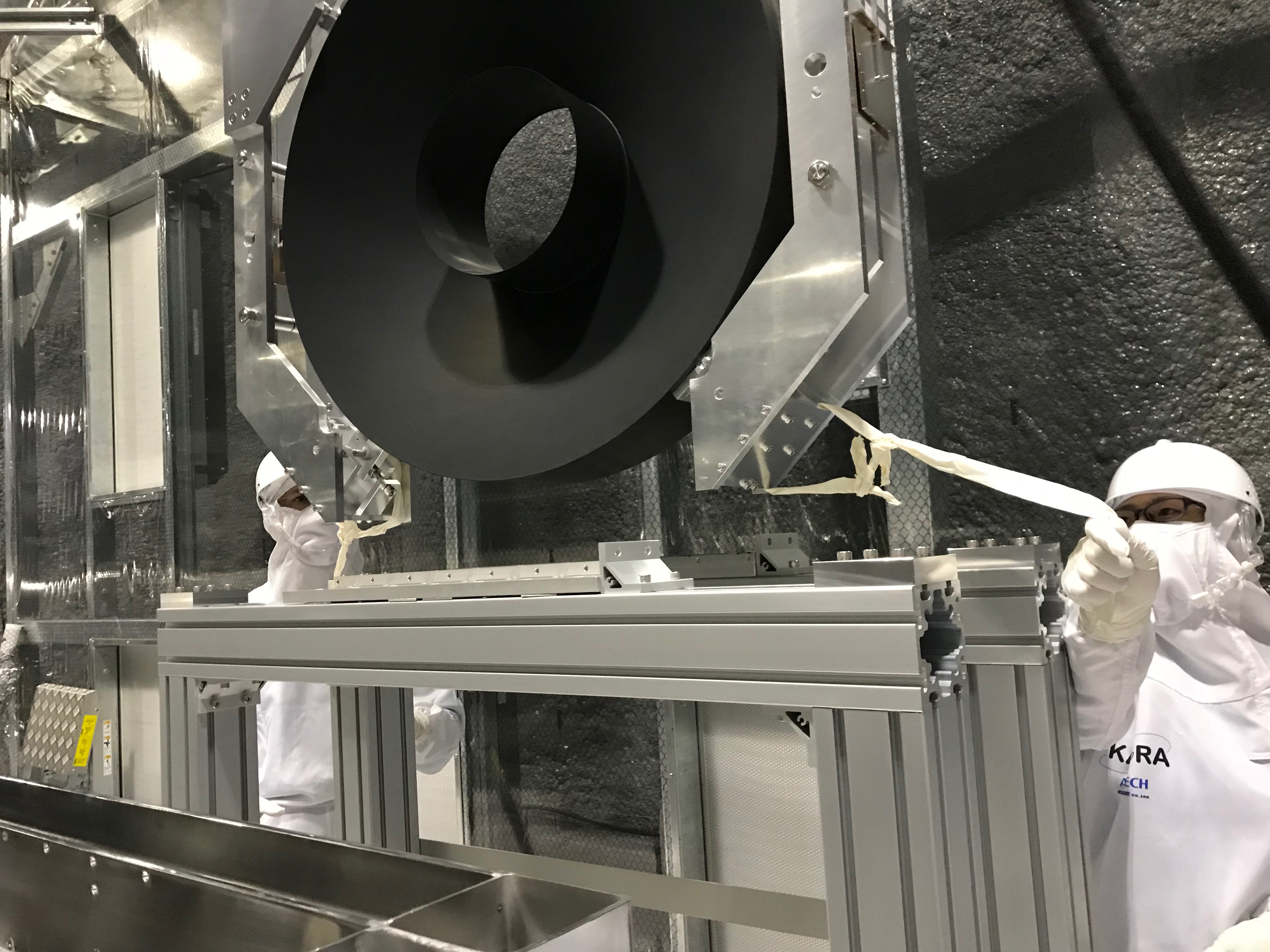
Taking out the NAB suspension
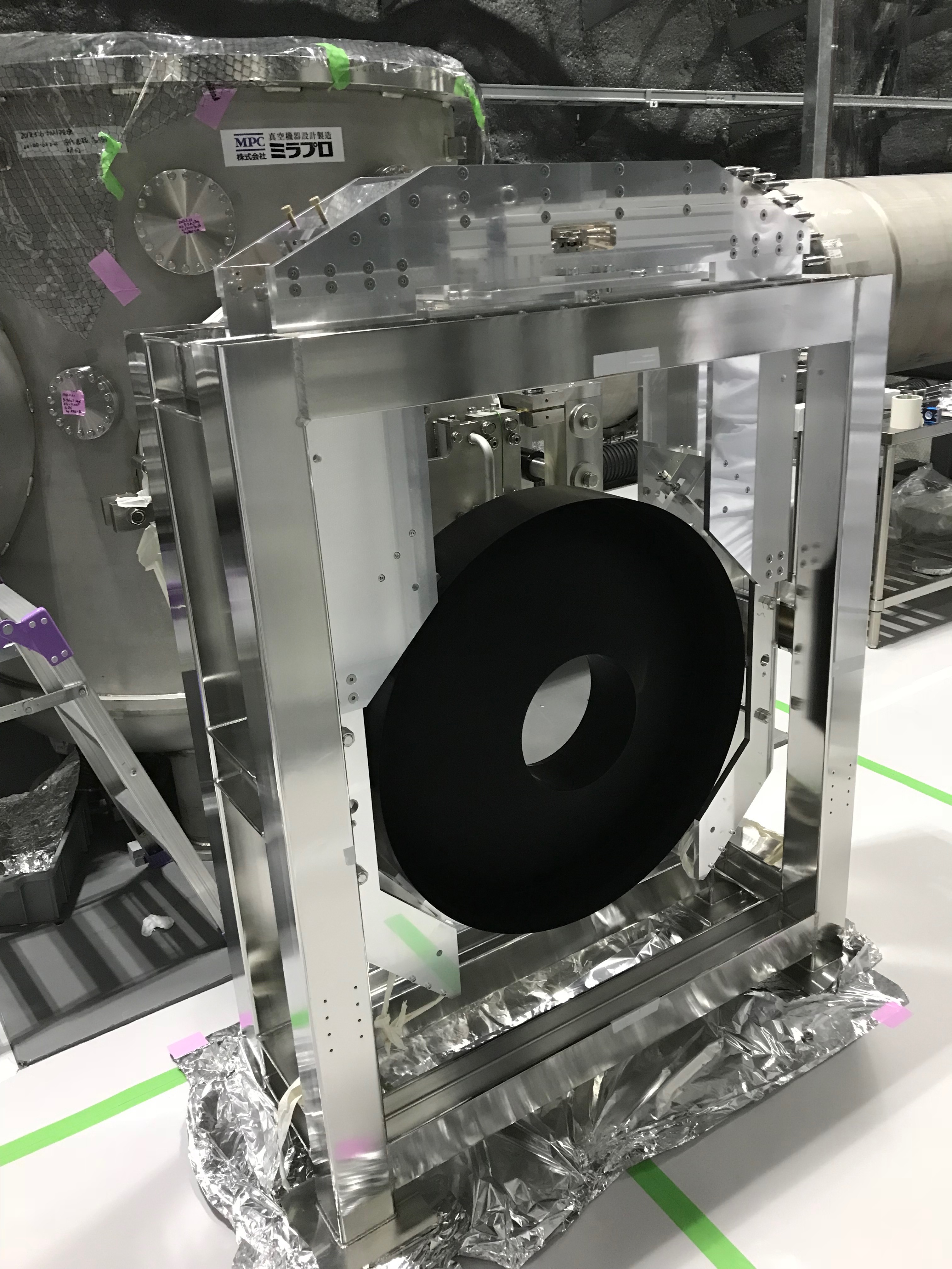
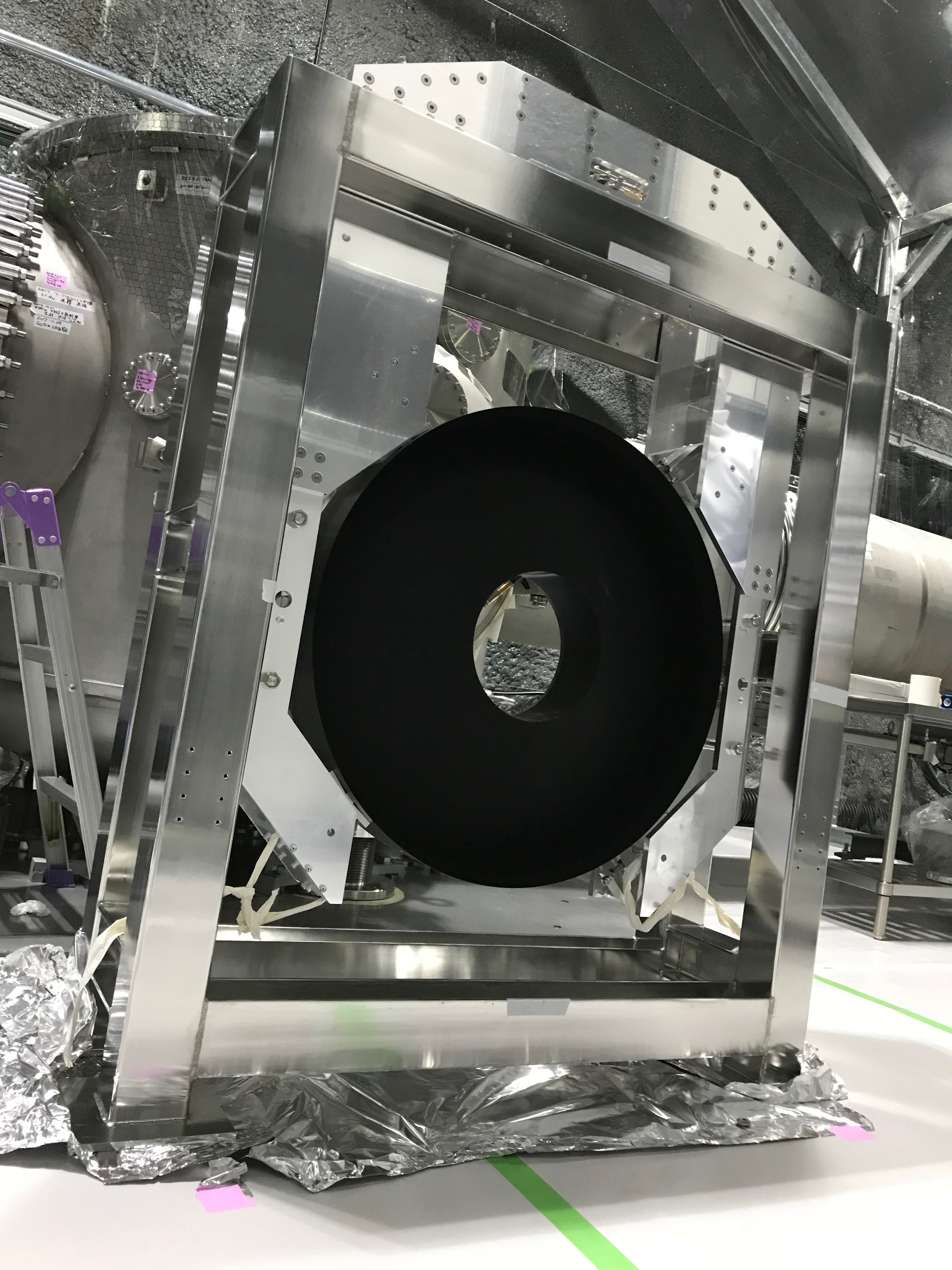
Removed the NAB suspension from the jig (Fig. 2-5). We sometimes moved the inner tower so that the NAB suspension could launch from the jig The crane's horizontal move was very rough and it is easier to move the jig than clicking the crane one by one to try to control the suspended load precisely. Even more, we intentionally broke/decompose the jig so that the NAB suspension can launch easier.
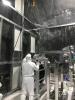
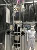
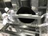
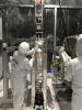
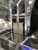
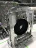
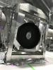
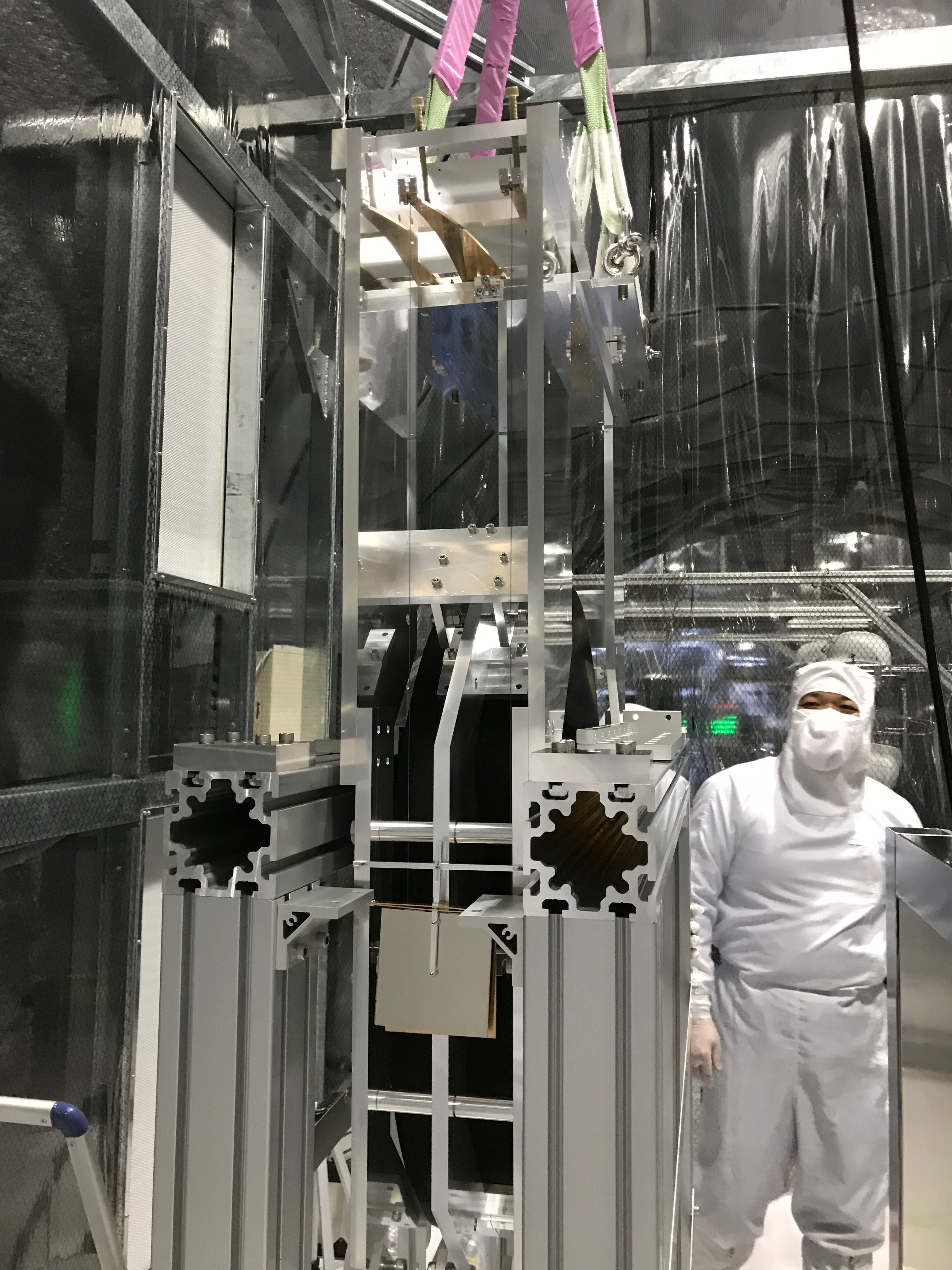
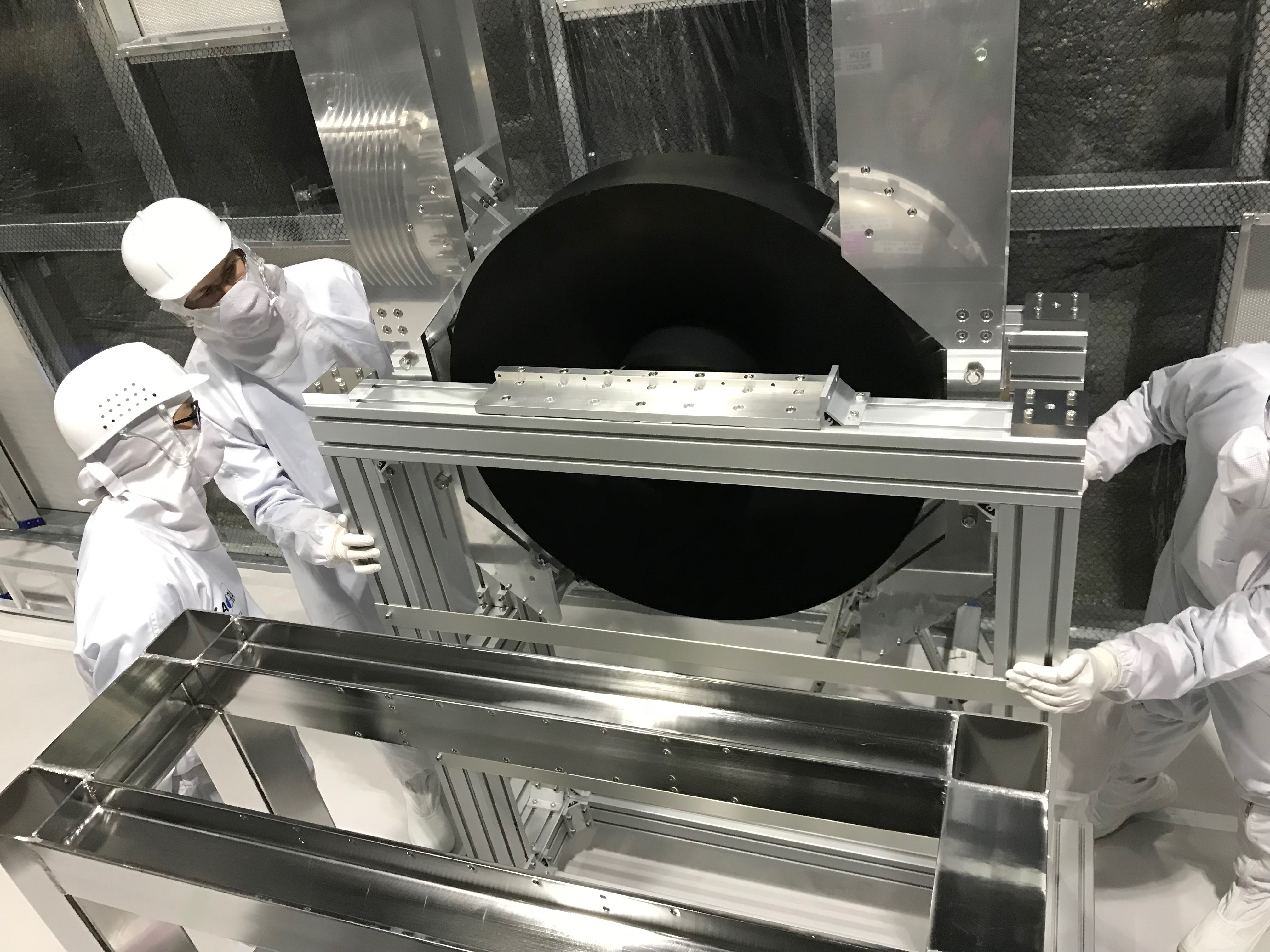
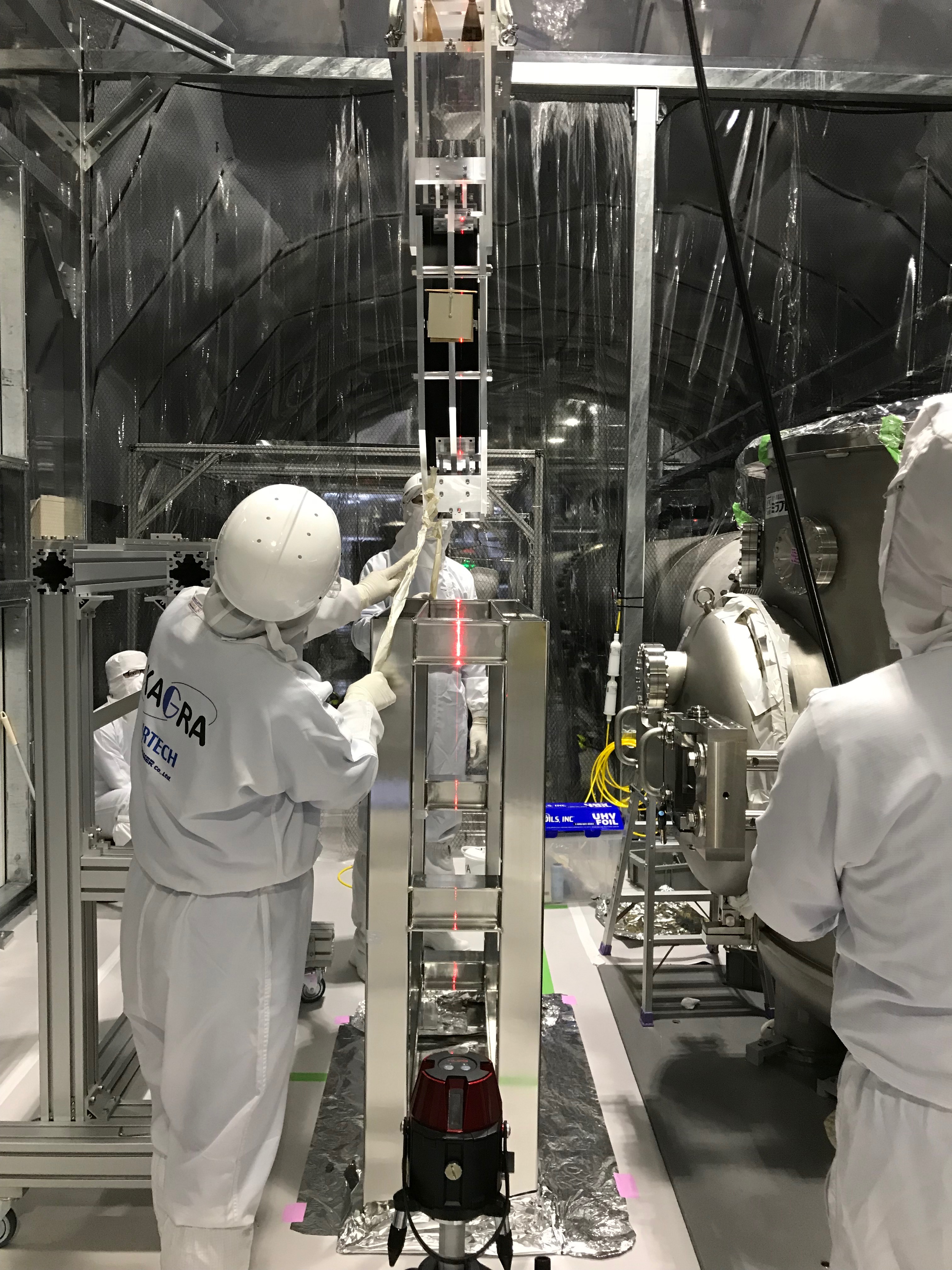
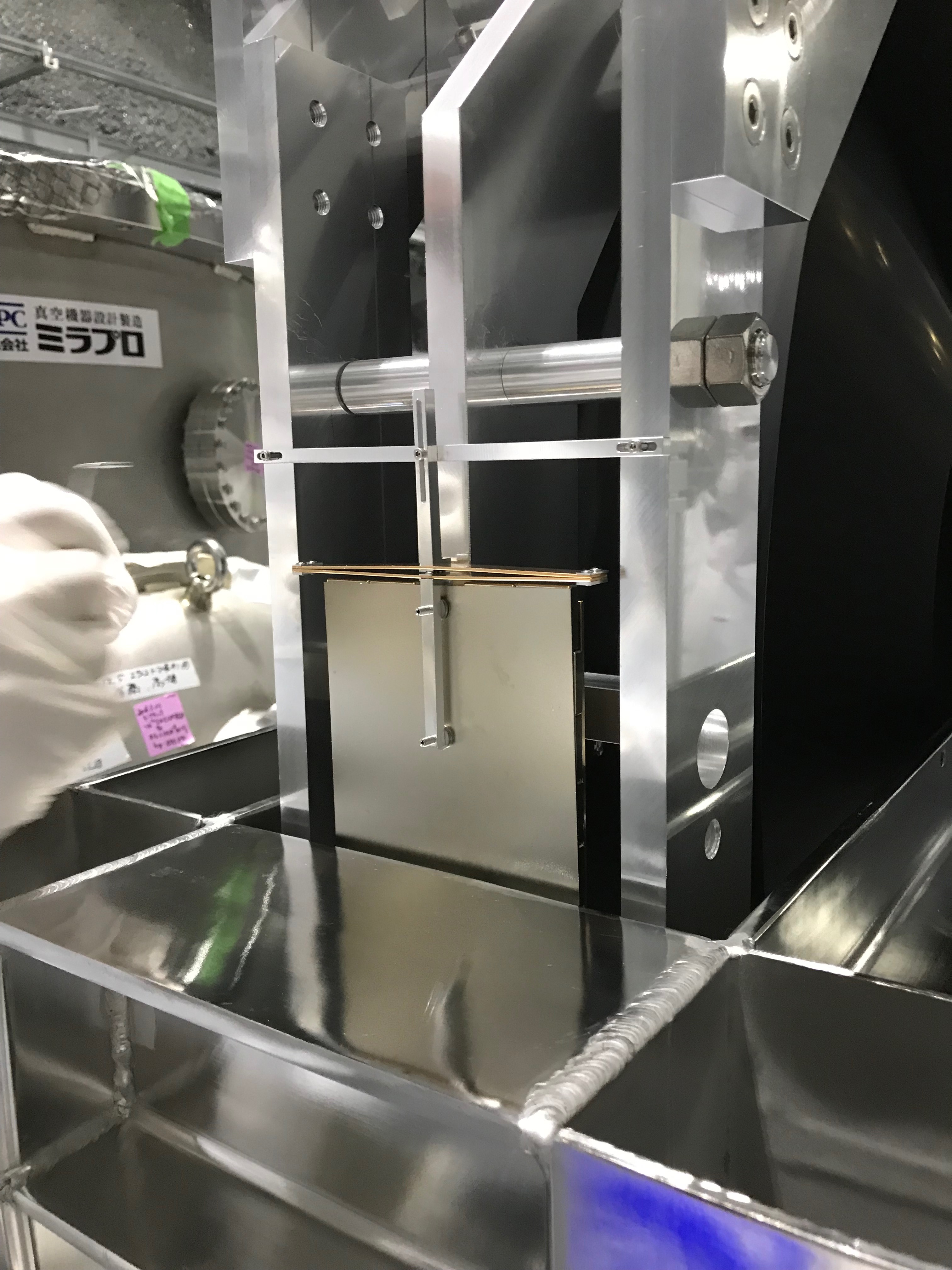
Inserting the NAB suspension
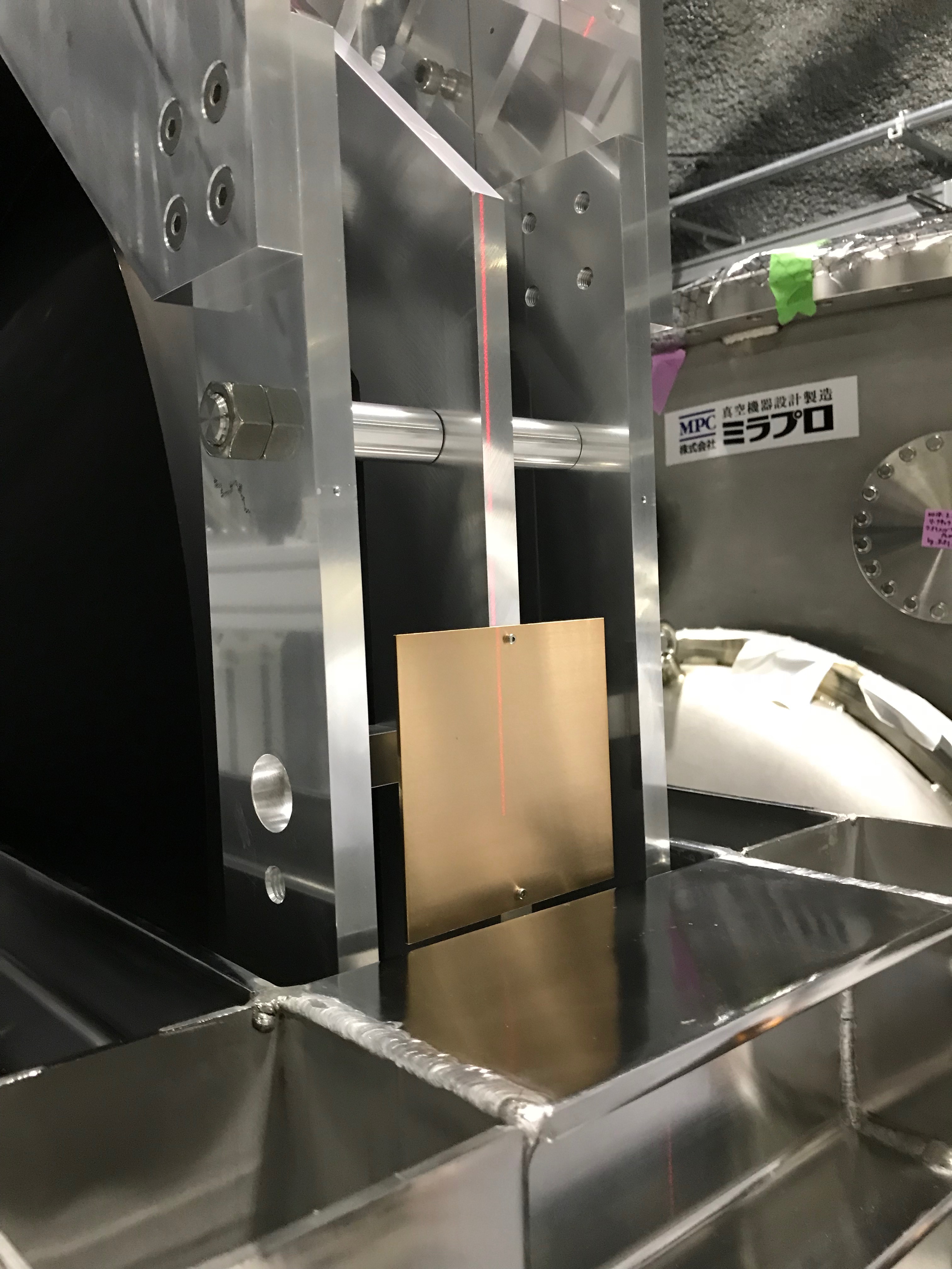
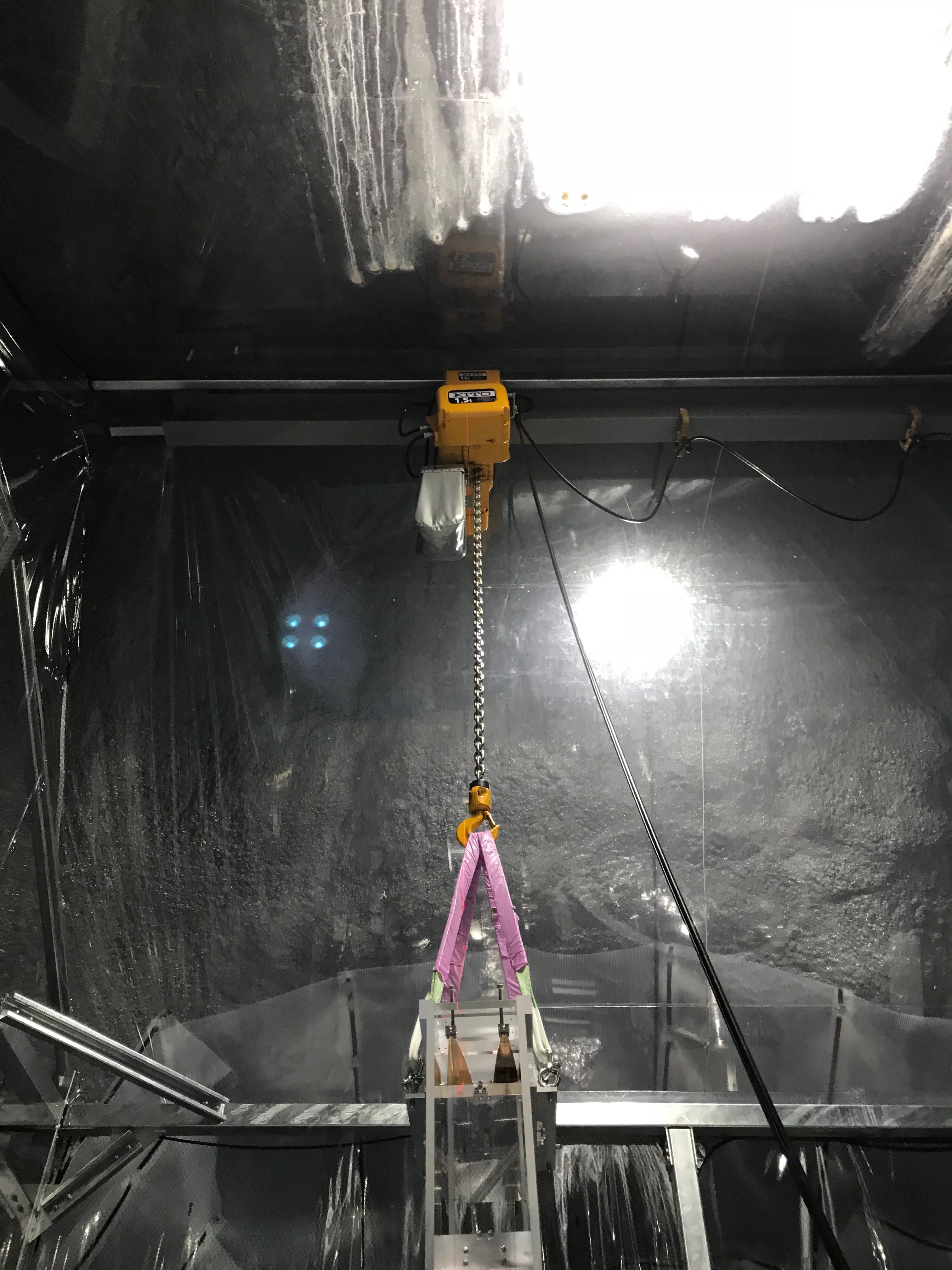
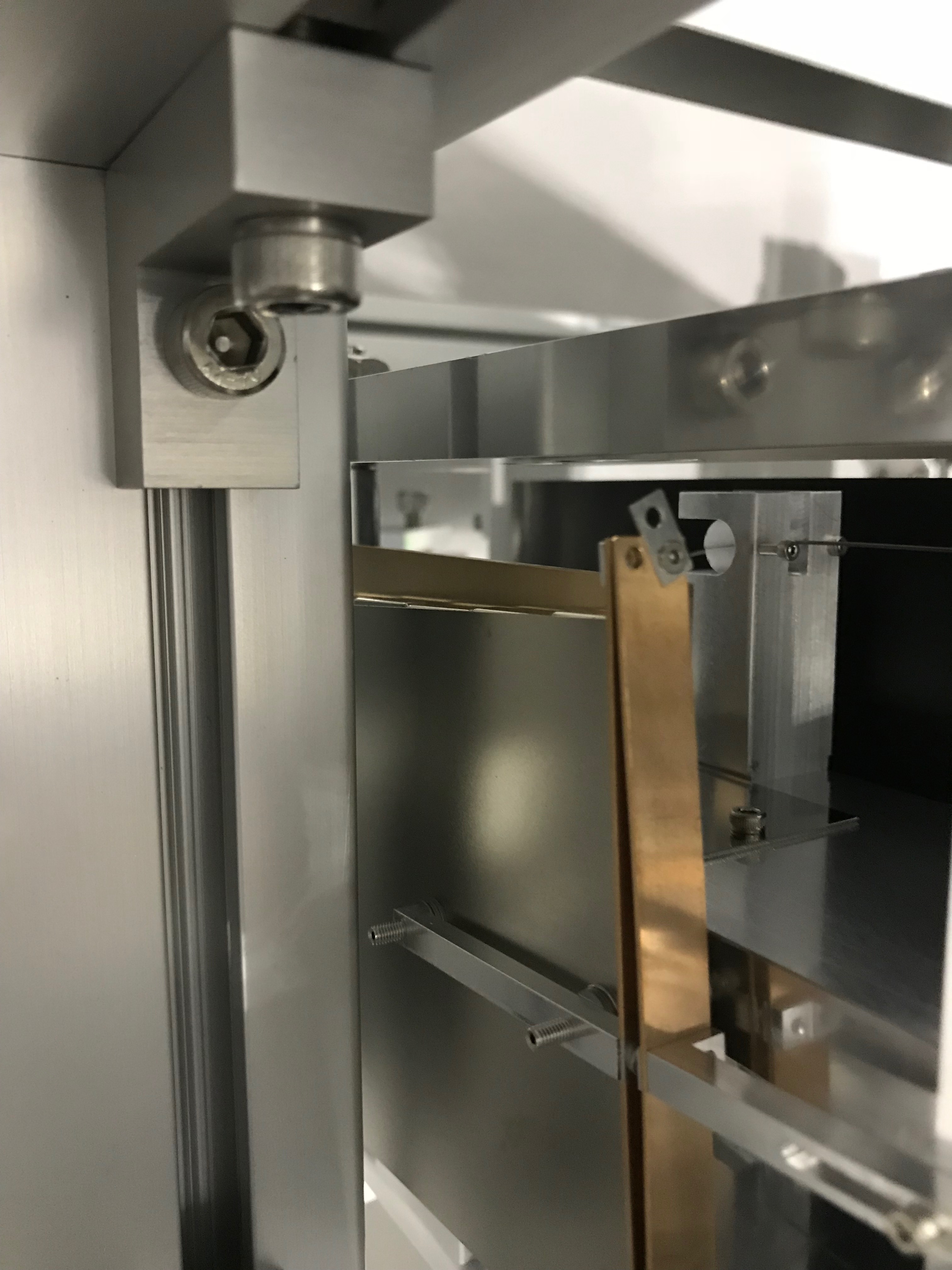
We tried to insert the whole structure into the inner tower. Because the crane was very rough in the transversal direction, we determined to use leads to damp the swing of the NAB suspension (Fig. 6, 7). During the process, we sometimes moved the inner tower so that it won't interefere against the NAB suspension. We found some of the screws fixing magnet plates were about to interfere against the jig and decided to detach those magnet plates (Fig. 8, 9).The laser level's vertical line was shooting the "probably" center lines of the inner tower from its side, and the crane's position was tuned so that the crane chanes and so on can be hung along with the laser line (Fig. 10; in this figure you can see the vertical universal laser line on the crane and the chanes). The interface plate of the NAB suspension was bit by the inner tower slightly, but we can move the NAB suspension in the transversal direction so that the screw holes (NAB suspension) and the holes (on the inner tower) can match as much as possilbe... finally one side of the screw hole array could be matched, but the other side was not... Anway it was inserted (Fig. 11 and 12). Then we measure several relative displacement; later to be reported.
Notes
- A screw which was fixing the vertical spring of the damper had been detached (Fig. 13)... no idea when this had happened. We did not know the reason but we just fixed it with new yobi screw.
- While inserting the NAB suspension into the inner tower outside, we found the damper plates would interfere with the inner tower's structre. We detached both of the damper plates. Need to consider how to get back those.
- Found some imbalance of measurements of relative distance of several part to part... need to be confirmed.
