[Tahara, Sakakibara, Nakano]
1. Replace a collimator lens
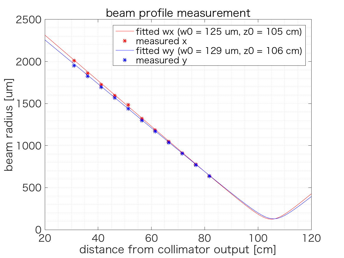
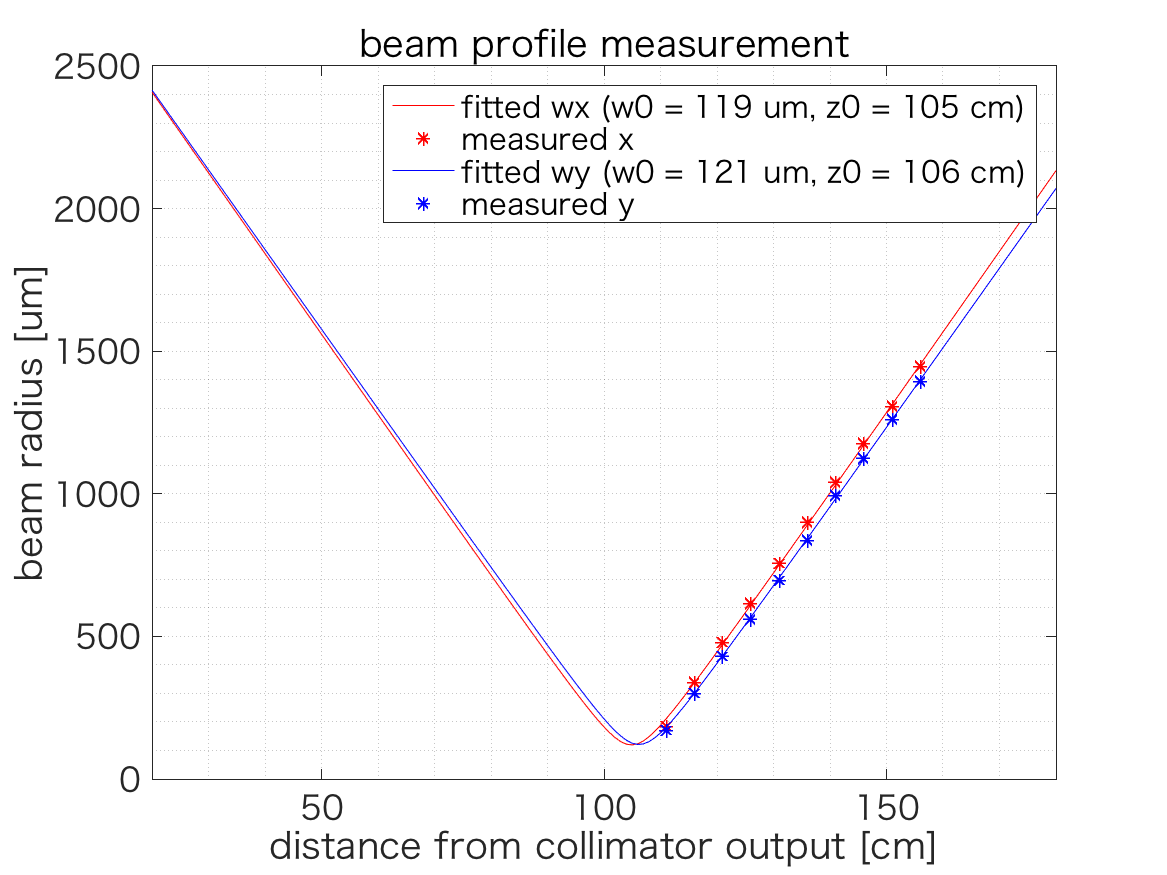
As the previous report, we used a lens with the focal length of 250 mm to collimate the beam toward the Faraday. That was too weak, and we replaced that by the one of a focal length of 200 mm. After replacement, the beam profile was measured. The result is shown in Fig.1 The origin of the z-axis is the output point of the fiber collimator.
2. Installation of a Faraday isolator
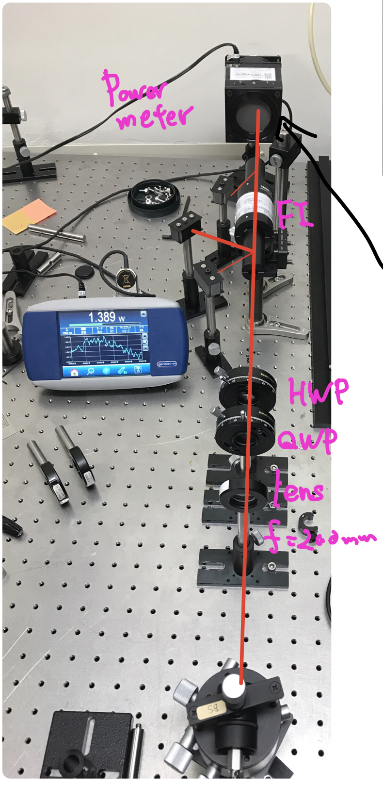
The Faraday isolator is installed at the position where the beam size is smaller than 3 mm. Figure 2 shows the layout of the Faraday and wave plates.
The transmittance of FI is (1.4 W)/(1.5 W) = 93.3 %. It is consistent with the catalog spec of 92 %. The power is measured by the power meter putting before and after the FI directly. The polarization extinction ratio is (60 mW)/(10 W) = 0.006.
3. RIN re-measurement
The RIN was measured again, and we saw the structure in the RIN reported on klog5055. Therefore, that structure is not because of the back-reflection to the fiber amplifier.
To confirm that is a real intensity fluctuation, we divided the beam into two paths just before the PD and the beam was injected to another PD. Then, we compared the spectrum of each PD. The spectra had the same structure. Therefore that structure would be the real RIN structure.
4. Backscattering error
During the operation, the fiber amplifier has stopped once due to the backscattering light. To recover the fiber amplifier, we have to re-connect the cables such as the power cable and USB cable between the PC and the fiber amplifier. It is not written in the manual, so we should remember this recovery procedure.