[K. Nagano, Yokogawa, Sugimoto, Ko. Yamamoto]
(This is a report of work on Mar. 30th.)
# Summary
- Two QPD interfaces were installed to EY0 rack. Using them, two TMS QPDs for green light were connected to ADC0 ch13-16(QPD1) and ch17-20 (QPD2).
- Althogh we tried centering the QPDs, it was difficult and centering was not good. This was because the green light was faint.
- We measured the power of the green light in green path (just after periscope optics for green) to be 1.6 uW.
- Periscope optics for IR path and two stering mirrors were installed using green light reflected by harmonic beam splitter in BRT chamber as a reference.
# Detail
## Installation of QPD interfaces and cabling
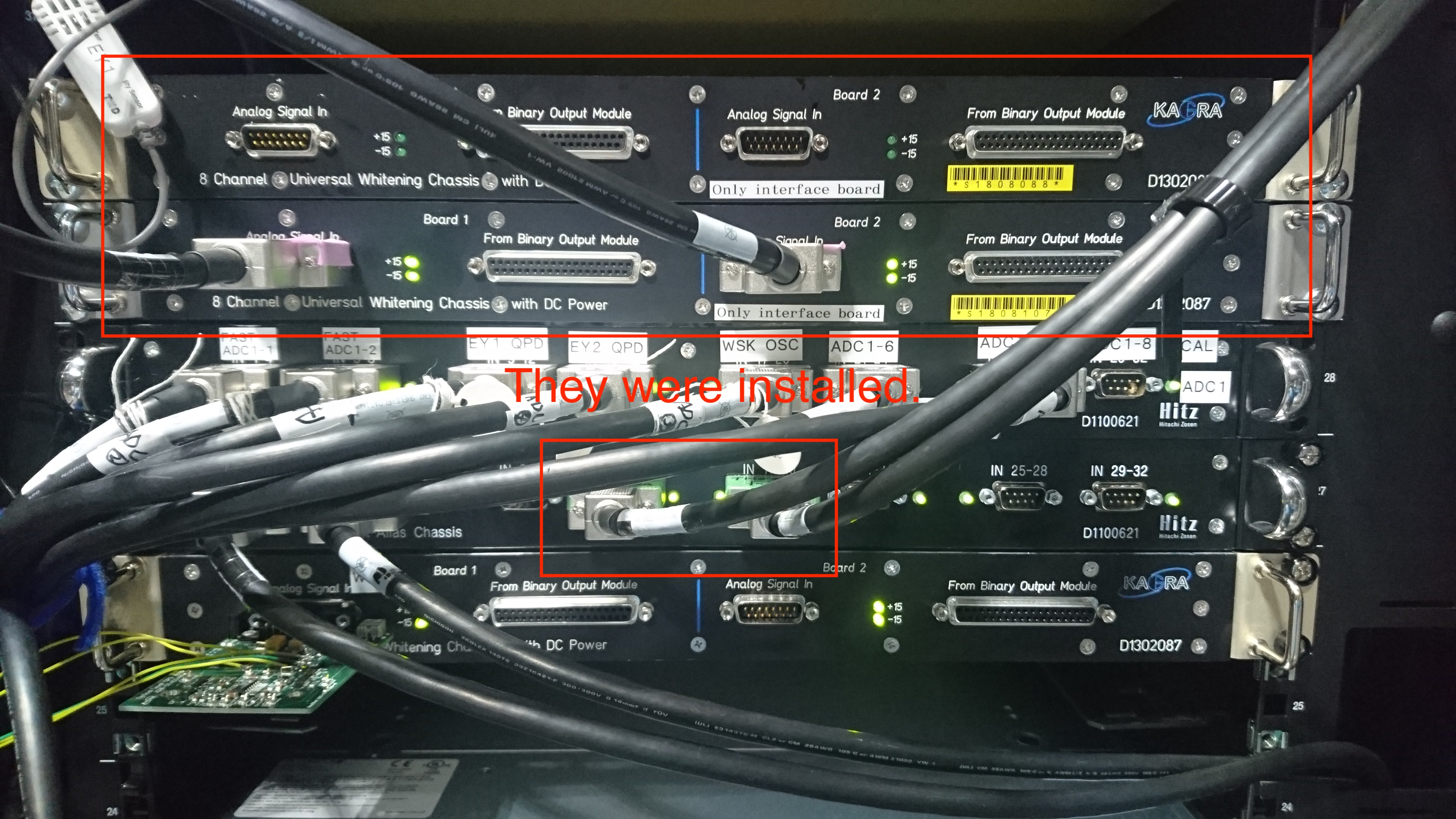
- Two QPD interfaces (S1808088 (for IR), S1808107 (for green)) were installed to EY0 rack.
- To S180817, we connected TMS QPDs for green light. The output signals from S1808107 were connected ADC0 ch13-16(QPD1) and ch17-20 (QPD2).
- About S1808088, we just connected power line.
-
You can find the picture of the status after the installation as follows:
## QPD centering
- We tried centering the QPDs. However, it was difficult and centering was not so good since the green light was faint.
- In ADC counts of QPD output with higher gain, green light was 20 counts although ambient light was 200 counts (LED light was off). When we cover the QPD placing an iris in front of QPD, the output counts was about 20 counts.
- Also, the output signal fluctuated at 60 Hz maybe because of ambient light.
- We centered the QPDs by placing the iris infront of them by hand.
-
After the try of centering, the value of micrometer of the QPD bases were as follows:
- QPD1: (yaw) 5.480, (pitch) 1.200
- QPD2: (yaw) 5.475, (pitch) 1.319
-
Problems
- QPD Dusb cables were not tighten.
- Beam size could be small. However, this is a trade-off of the sensitivity. If small tilt should be measrued, this is not so bad. Actually, when we misaligned the green beam on ETMY a bit (~1/3 of mirror size), we could not see any change of beam spot. (However, it was not so clear since the light was faint.)
-
Update ideas
- Make something to reduce ambient light effect.
- Make 60 Hz notch fileter.
- Tighten screws of Dusb on QPDs.
## Green power measurement
- We measured green light power using PDA100A wigh 40 dB gain and oscilloscope (1 MOhm input impedance mode) just after periscope optics for green light.
- Since the output signal fluctuated at 60 Hz, we measured the lowest value of the signals when the greeen was on and off.
-
The measured value was as follows:
- Green on: 206 mV
- Green off: 126 mV
- Increment: 80 mV
- Using the PDA100A sensitivity for 532 nm with 40 dB gain and high input impedance instrument is 5.1x10^4 V/W (from manual), we can calculate the power of green light to be 1.6 uW.
## IR path installation
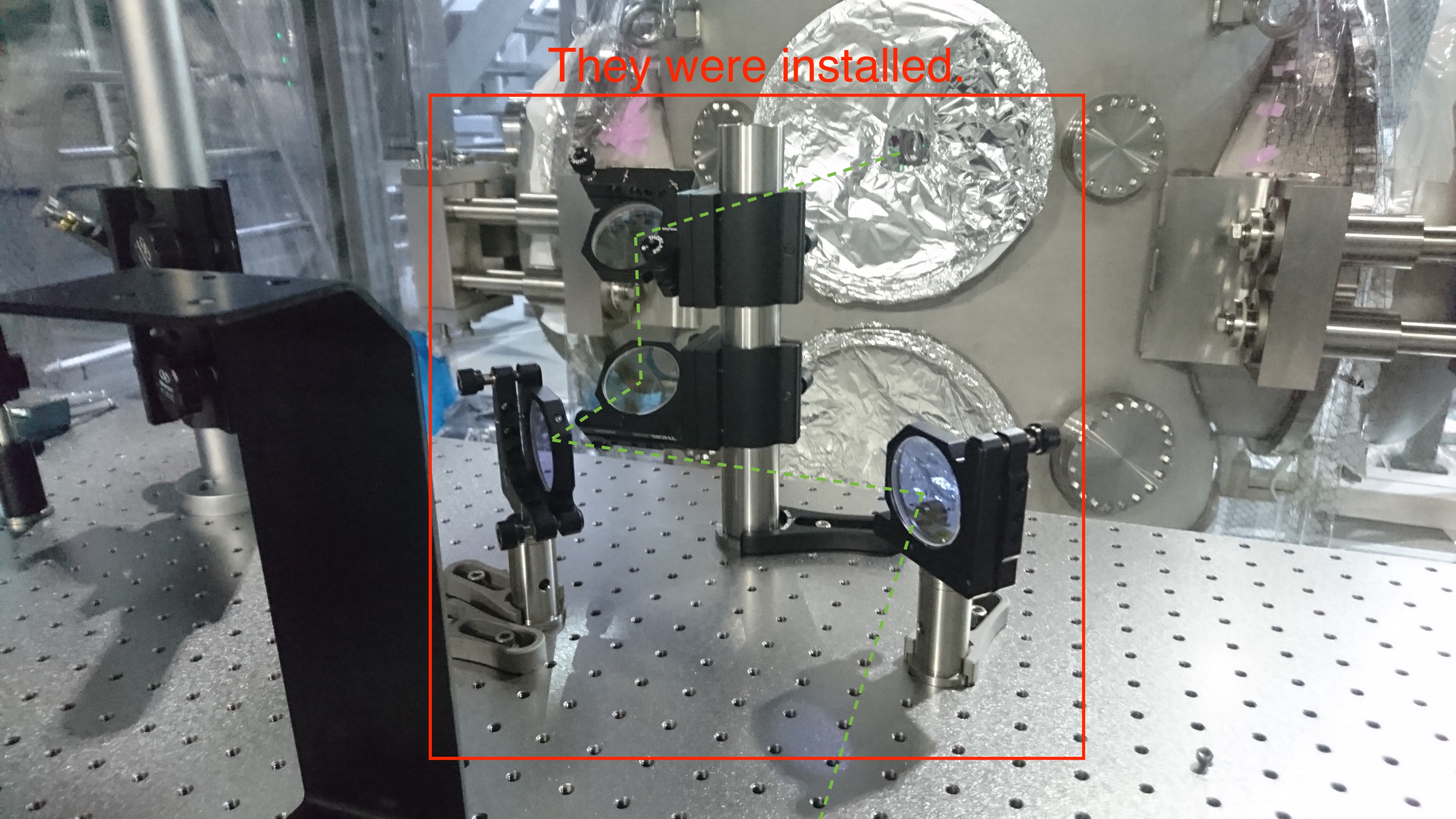
- Periscope optics for IR path and two stering mirrors were installed using green light reflected by harmonic beam splitter in BRT chamber as a reference.
- We did not install any lenses since we could not know IR beam profile.
- All installed mirorrs are PYD-20.
- The hight of the optical path on TMS bench is 100 mm.
-
Picture: