Miyo, Akutsu
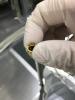
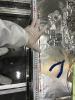
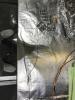
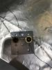
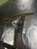
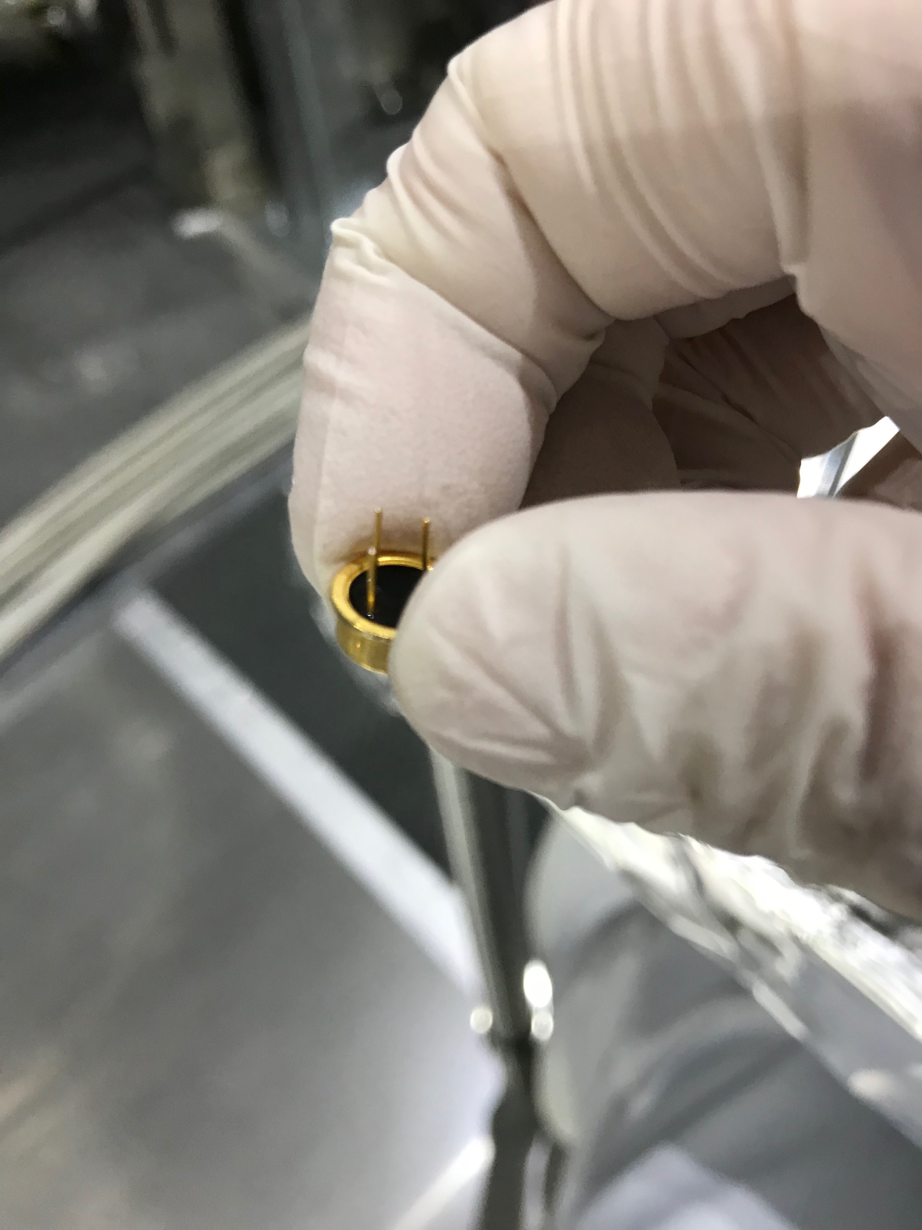
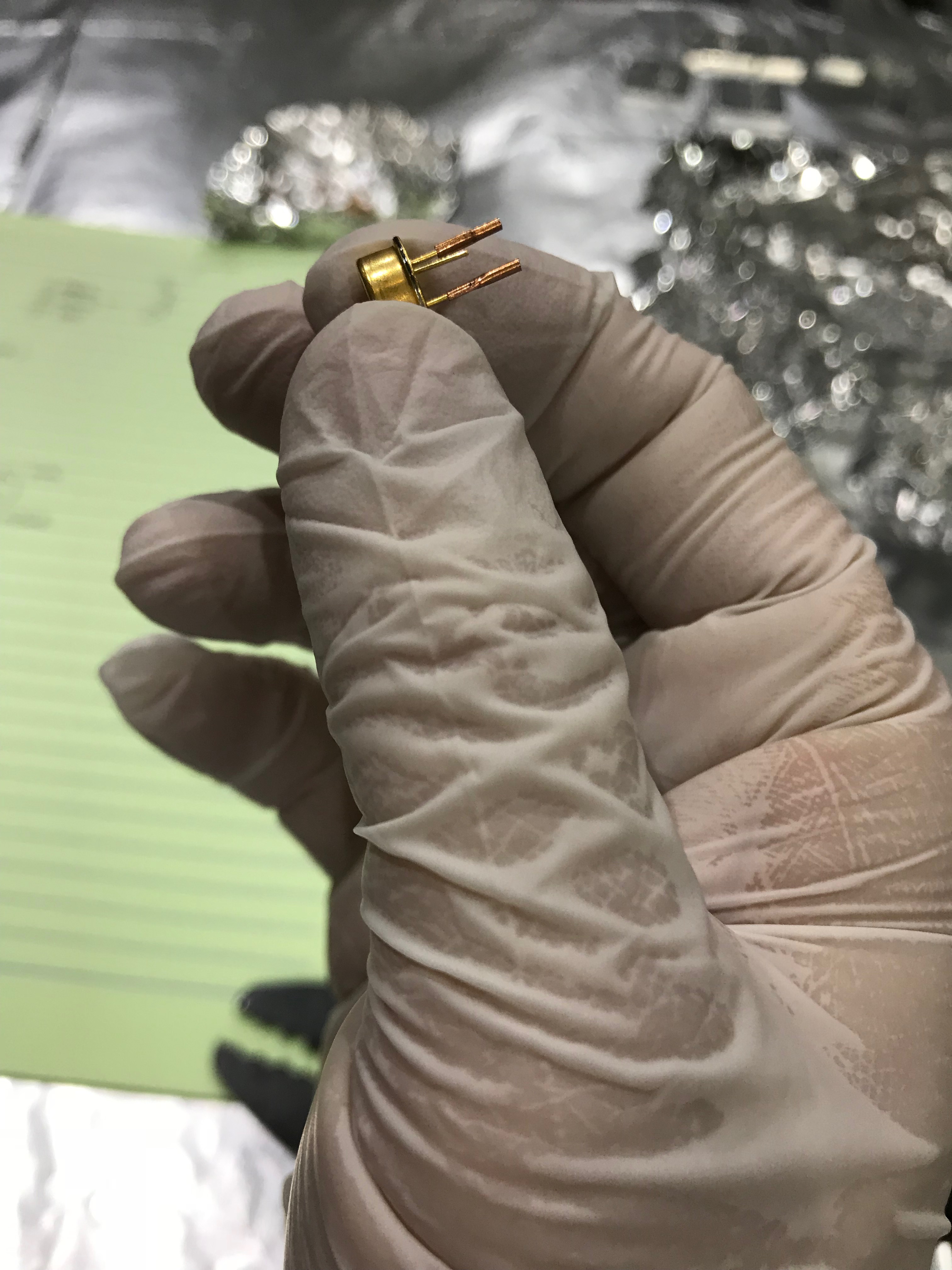
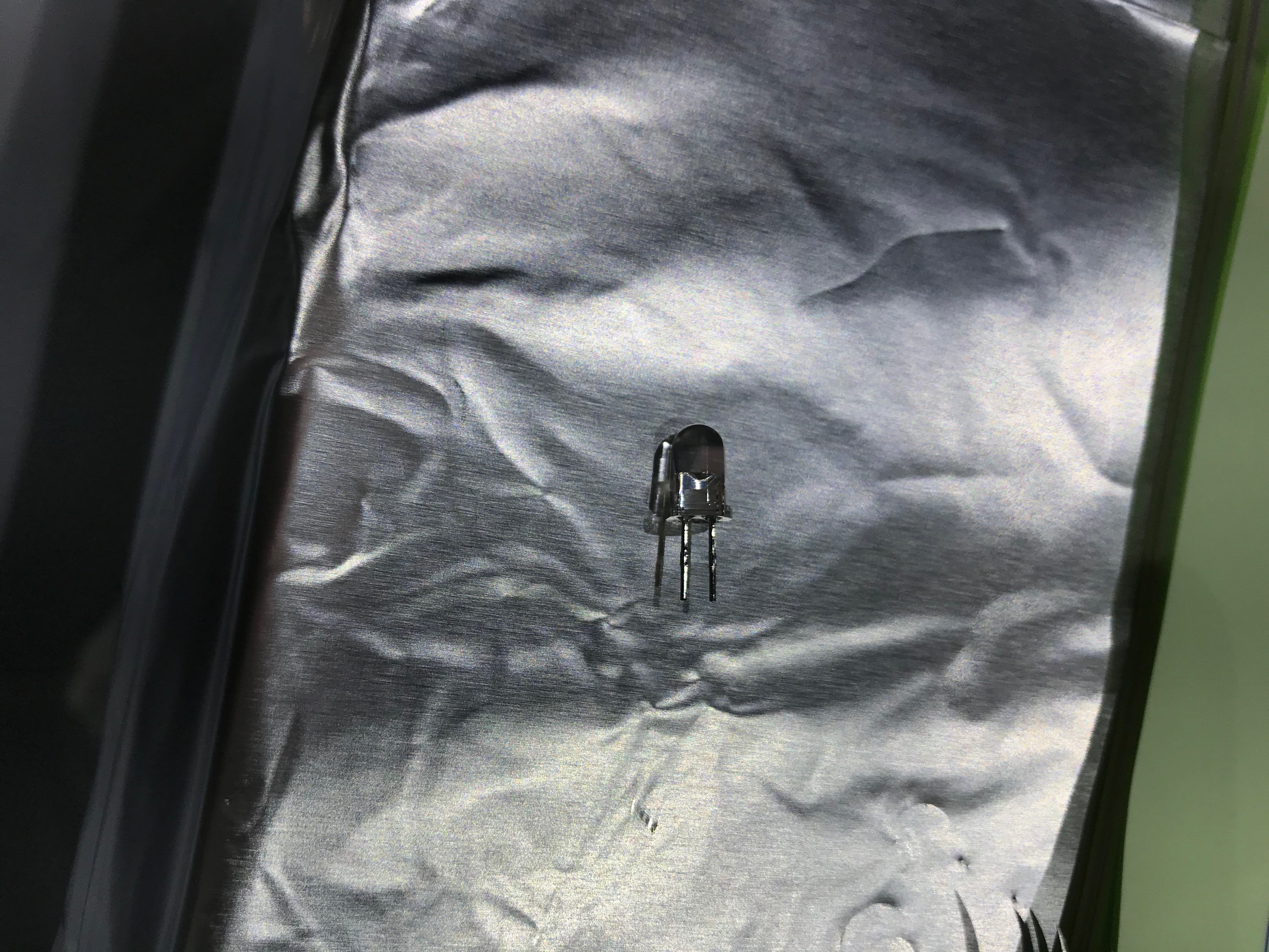
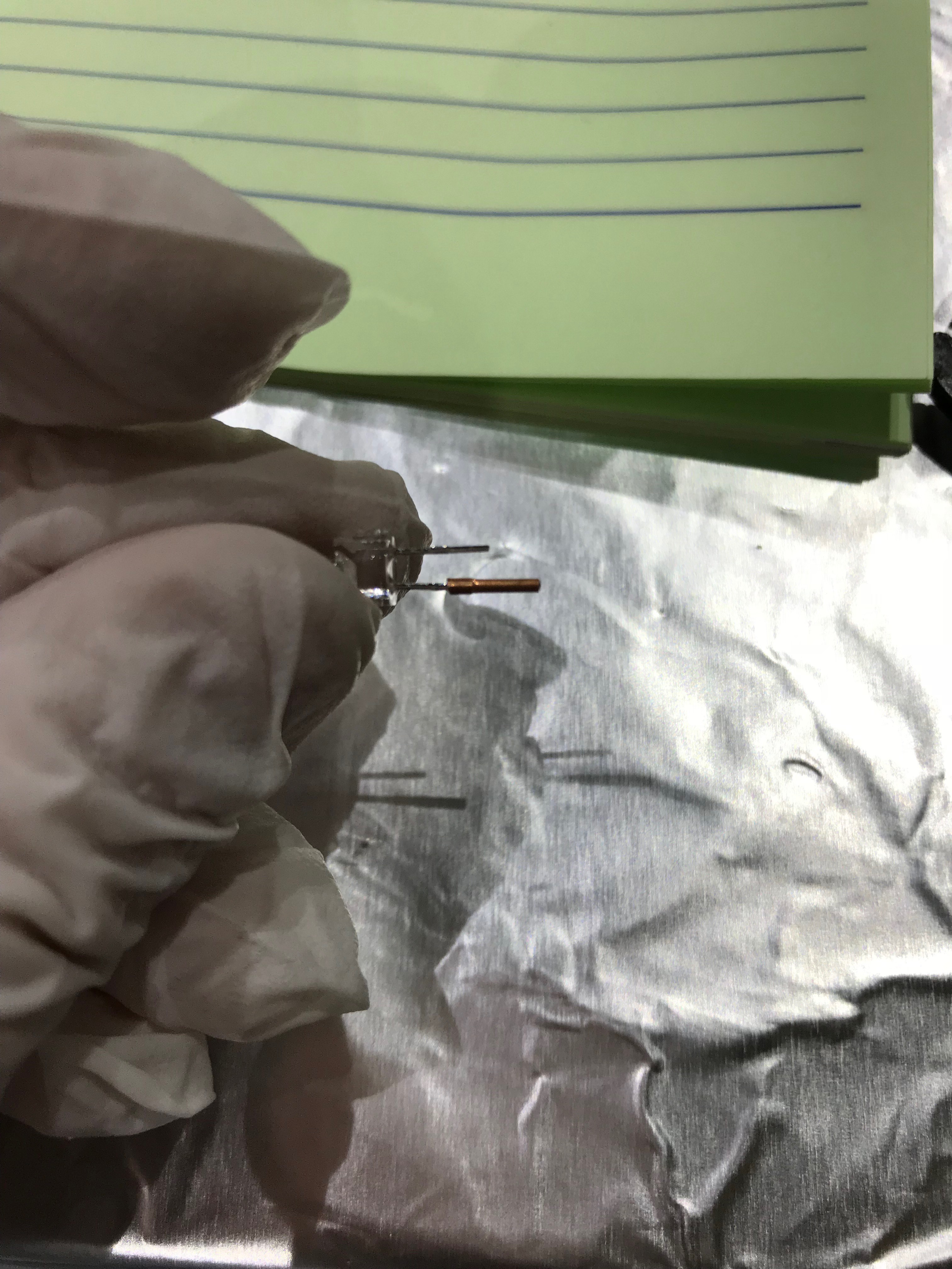
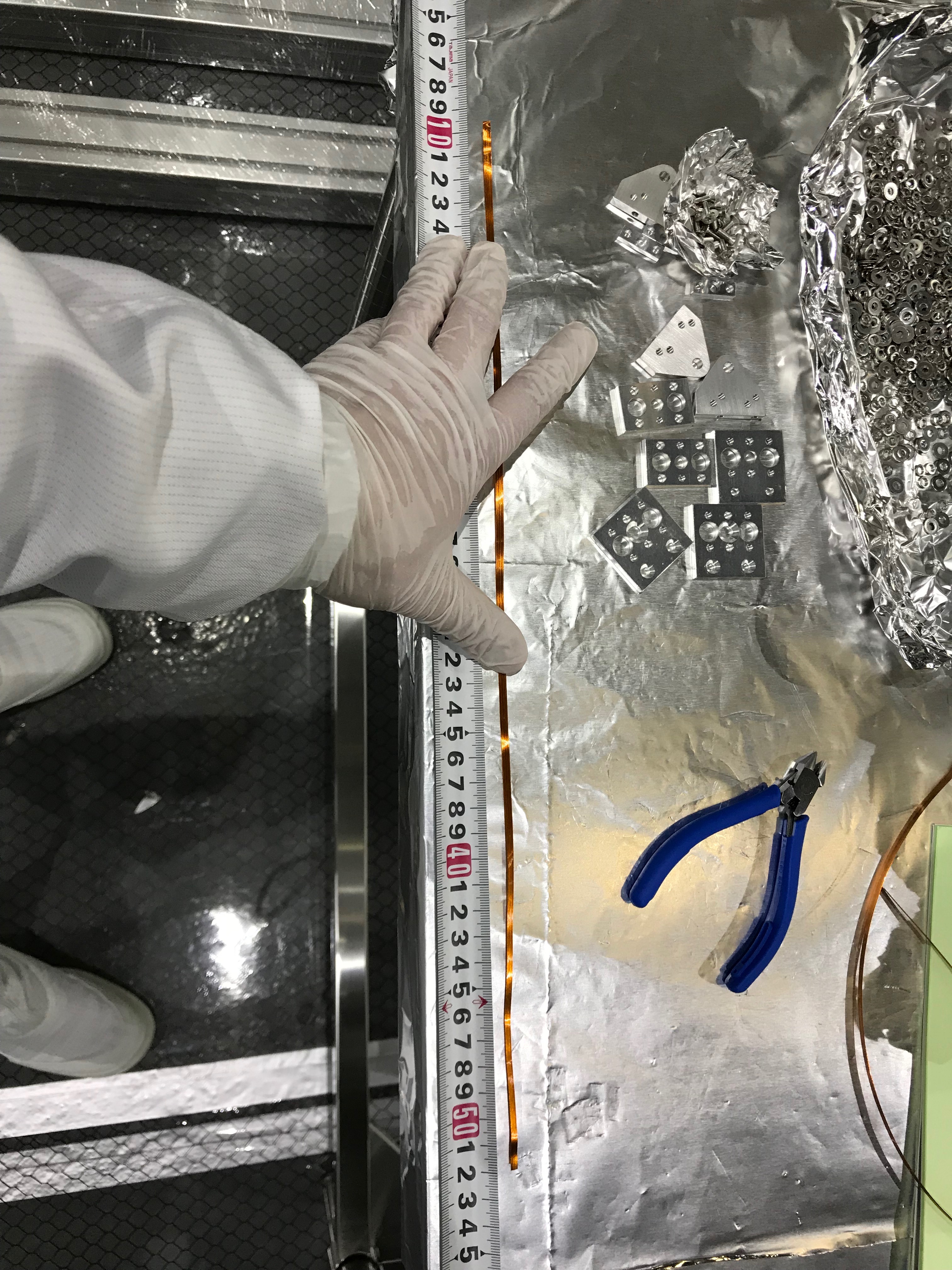
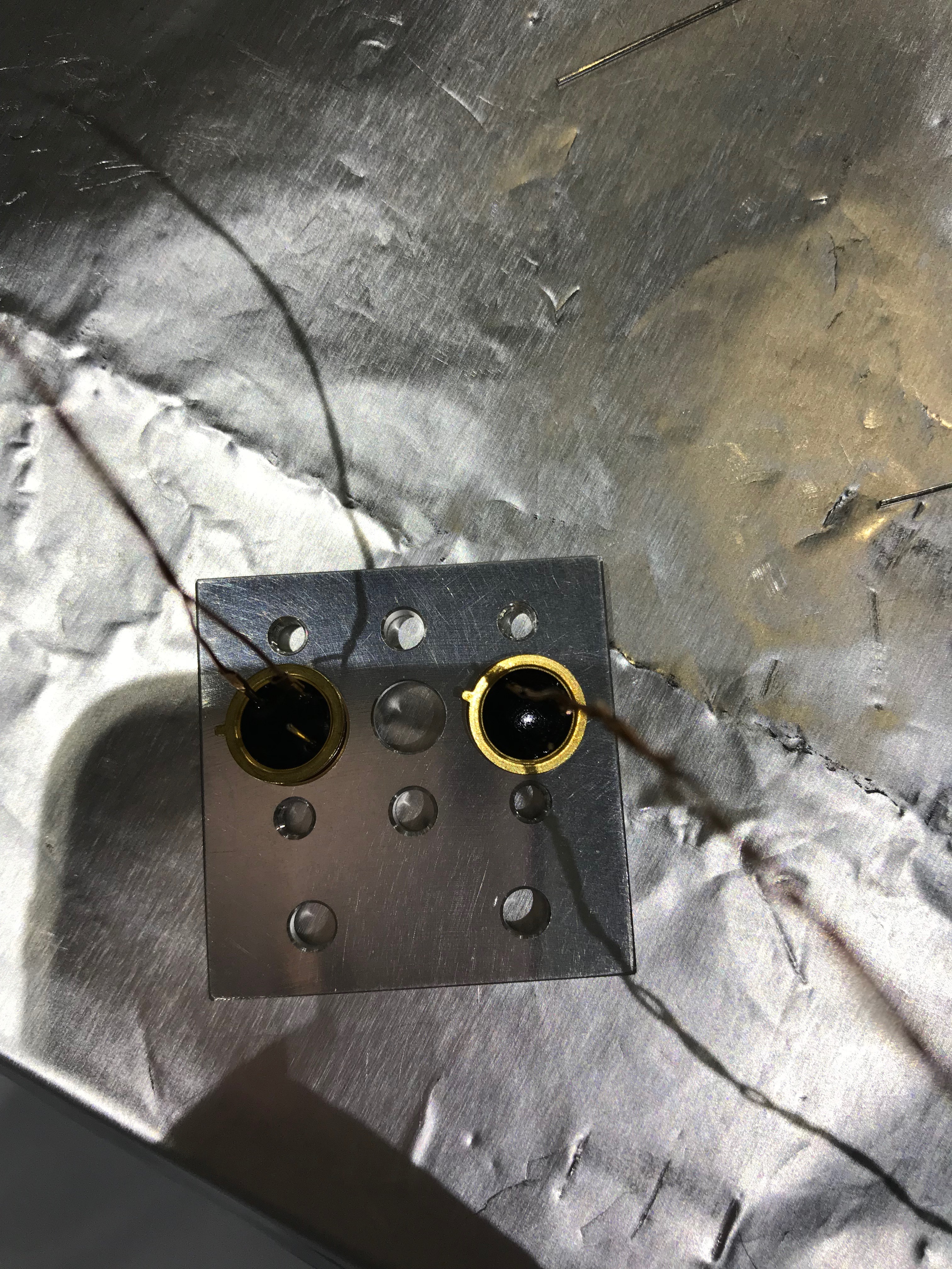
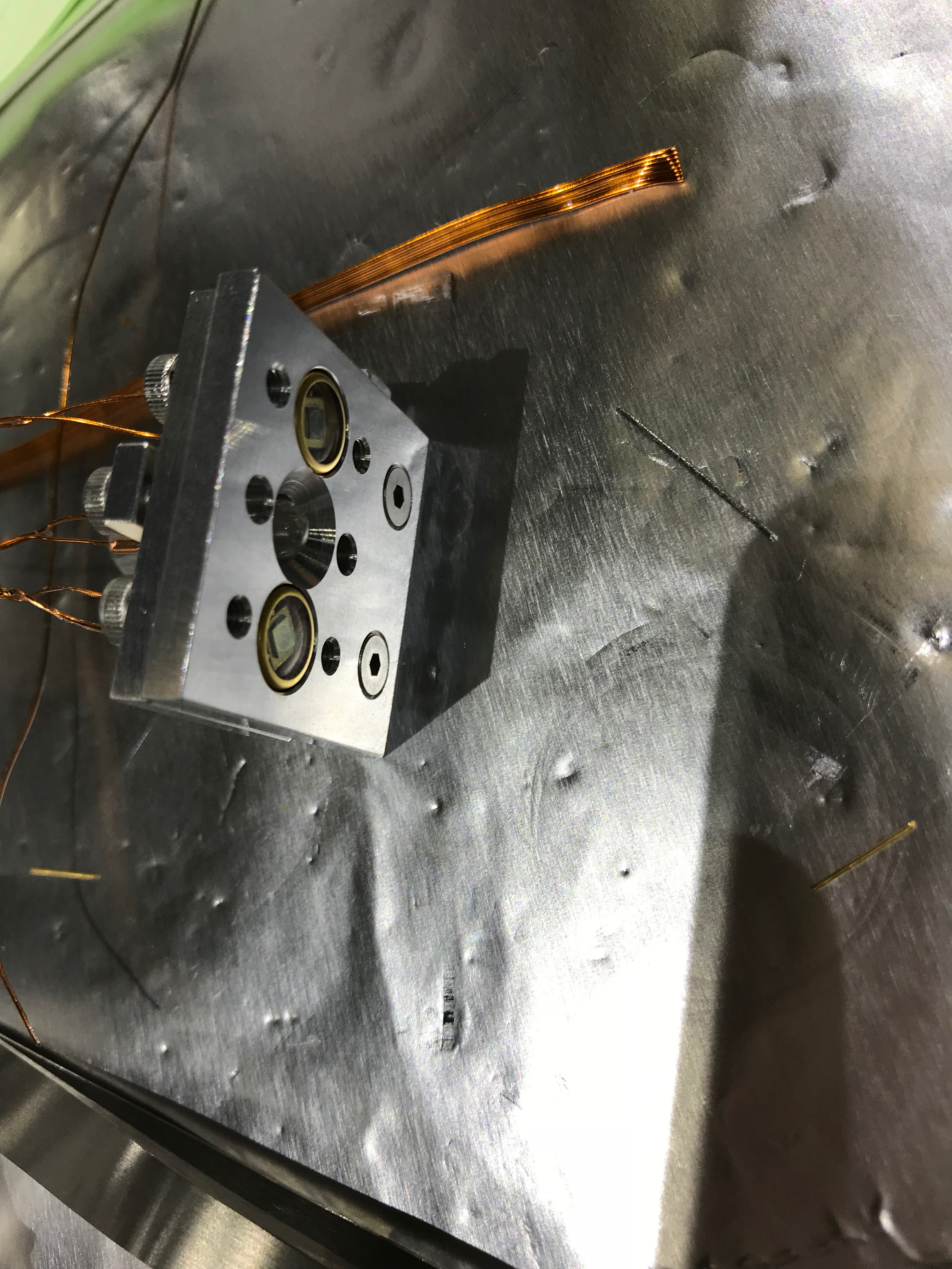
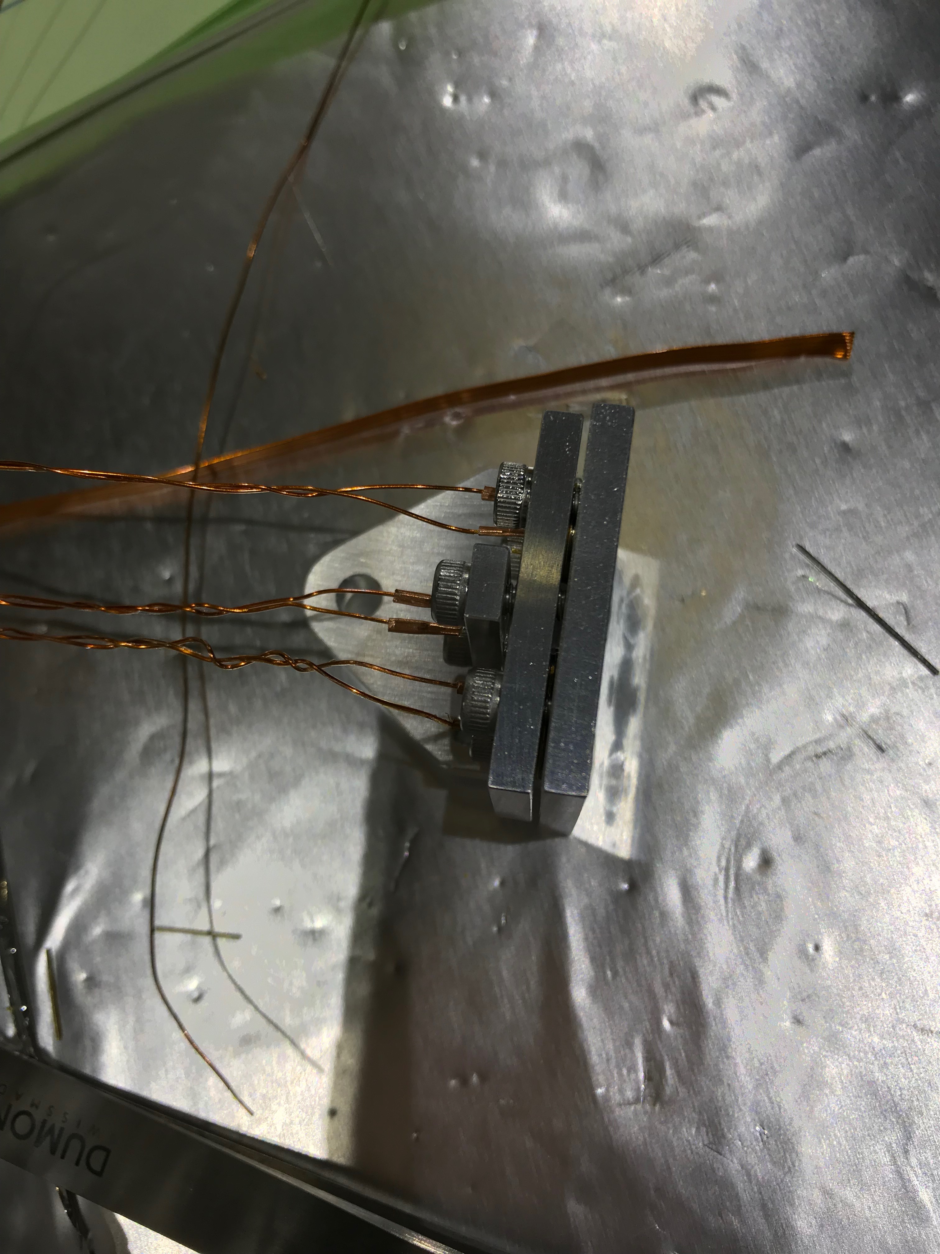
To assemble photosensor heads, we did some electric crafts (Fig 1, 2, 3, 4, 5, 6). Following information inputs from Ushiba-kun and Miyamoto-kun I got beforehand, we swaged the pins of the sensors with cupper pipes in one side, and kapton-coated wires the other sides, and checked the electric continuities. Then two PDs were firstly set to the head and then a LED. After that, wires from the two PDs were swaged to female burndy pins so that the two were connected parallelly, which meant each pin accepted two electric wires. Note that the pin swaging should be done after the PDs were located to their position, otherwise the PDs cannot be fixed by the retainer!!! For the LED, each wire for each single burndy pin; due to too small diamater of the wire, we needed to fill the remaining gap around the wire in the the same manner as for the thermometers. Fig 7 shows the rough alignment of the two PDs, and they were more alighned later. Fig 8 and 9 shows the resultant photosensor head.
Then we connected the photosensor head to digital system via OSEM satellite box so that we can observe signals online. So far it seems nice, but more detailed investigation should be done tomorrow.
More information is here.
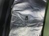
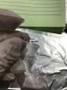
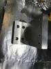
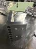
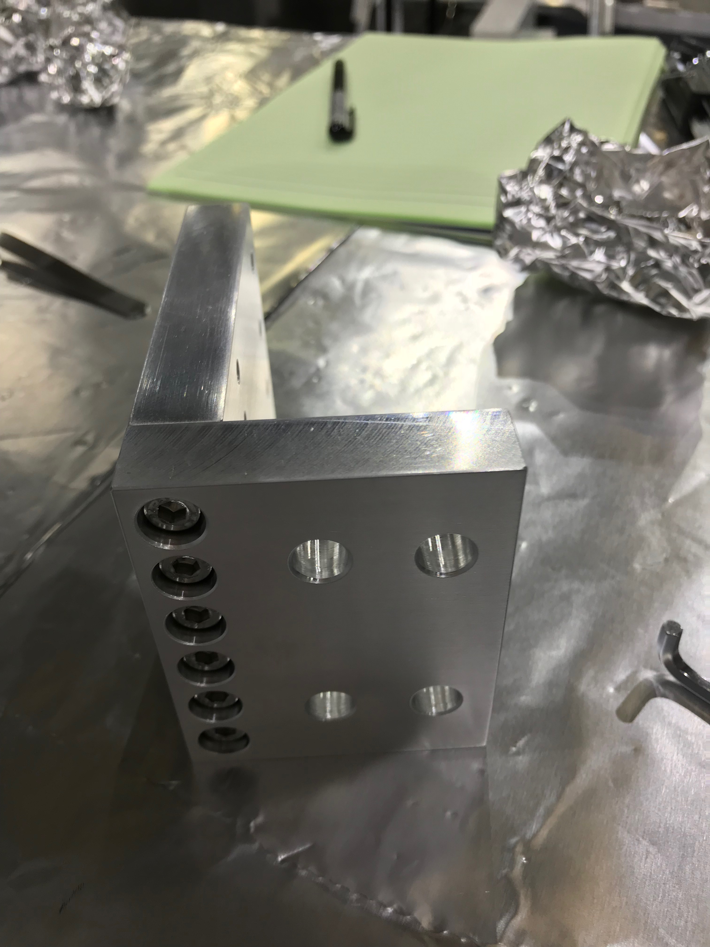
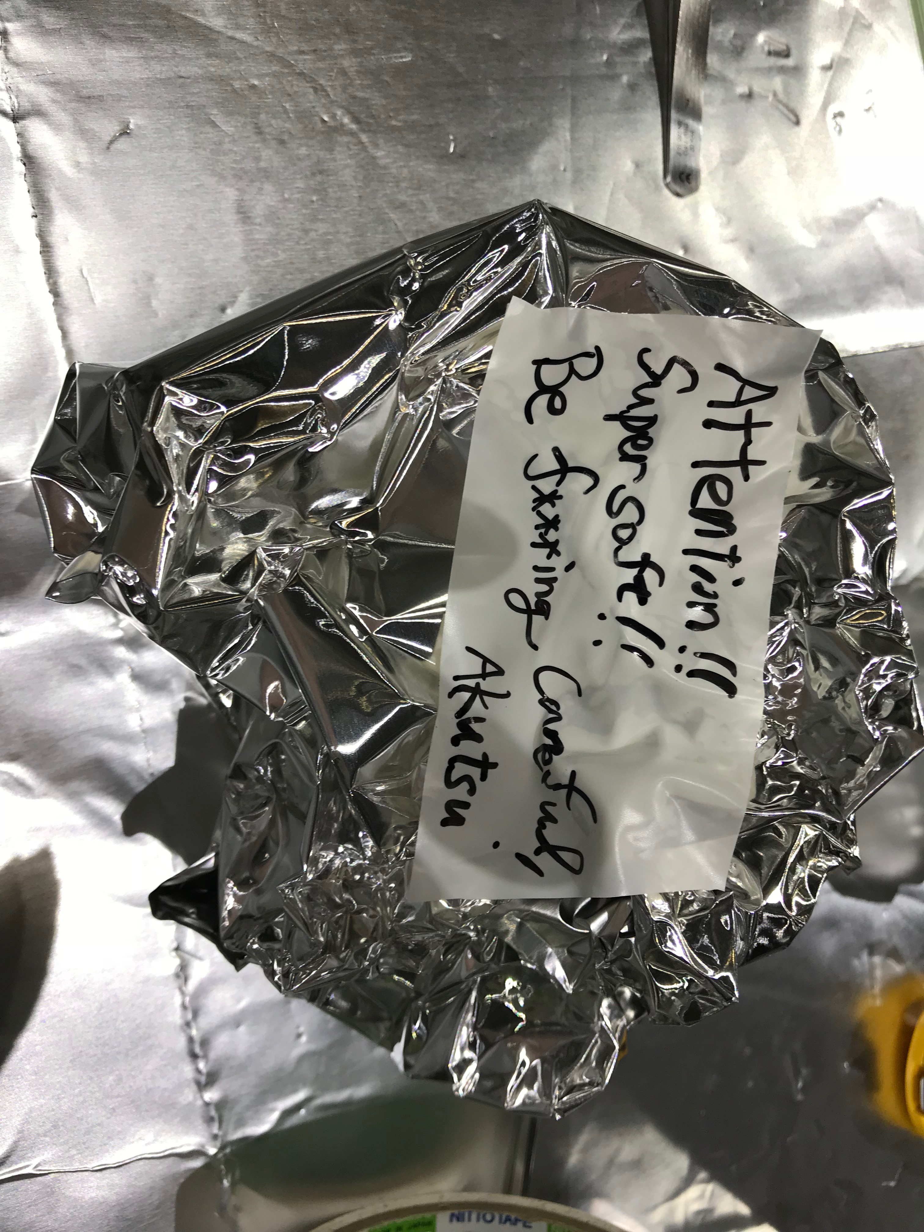
In additoin, an aluminum block, the adaptor for heat links was assembled (Fig 10, 11). That is too soft so be careful when you use it  (Fig. 12)


