[Okutomi with Miyo-kun's help]
I characterized three geophones for Type-A ETMX control test.
The geophones have better noise level than the expected accelerometers!
Target
To characterize the assembled geophones with measurements of
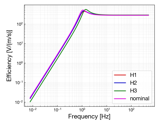
- Efficiency: a conversion from raw outputs to data in velocity or displacement
- Noise: sensor noise in frequency domain
Issue
- The geophone L-4C has each inspection sheet which gives the information of the conversion efficiency
-
But their individual parameters seems not to be valid any more
- Because a simultaneous measurement with the geophones and PEM seismometers has different level of ground motion to each other using the parameters on the inspection sheet
- So I estimated the parameters of geophone with a free run measurement to get the conversion efficiency
- Then the converted sensor noise of the geophones is obtained
Free-run measurement
-
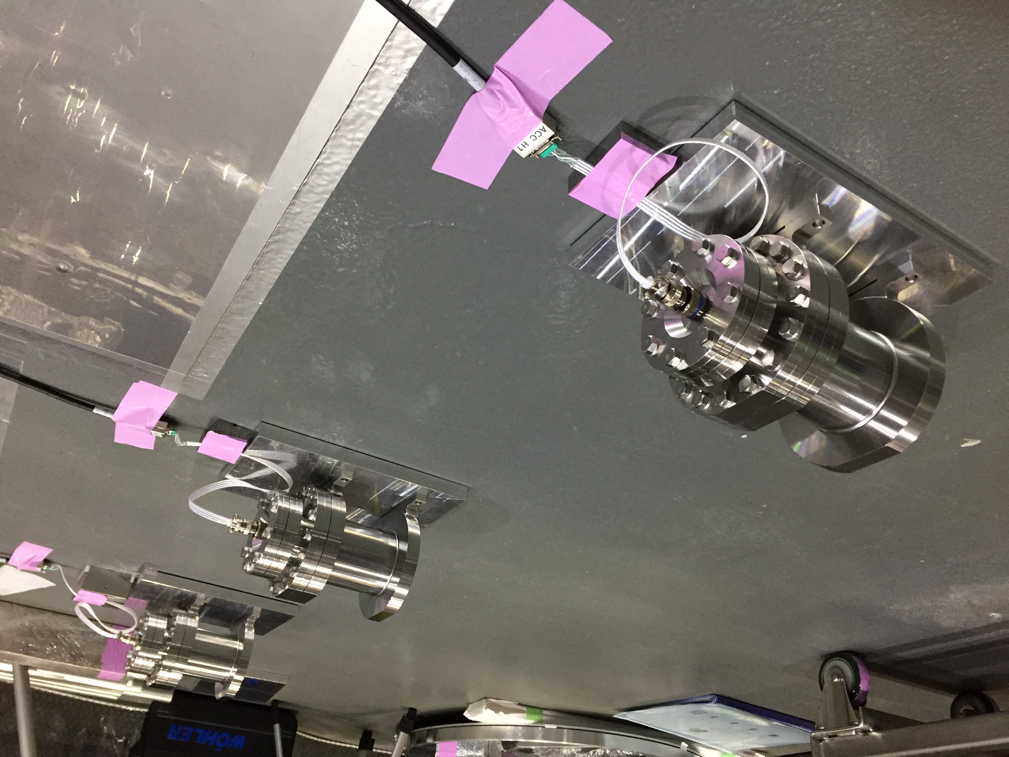
Geophones
- In-pod x3: with pre-amp circuit, set on each aluminum plate on the floor (for tilt adjustment)
- Naked: without pre-amp circuit, set on a table
-
Seismometers
- Trillium Compact x2 (JGW-S1707526): 45dB amplification with whitening filter, set in a corner of EXV room (outside of the clean booth)
- Trillium 120QA (JGW-T1707554): 45dB amplification with whitening filter, set in a corner of EXV room (outside of the clean booth)
-
Geophone parameter
- Generator constant [V/(m/s)]: assumed that the values in the inspection sheet are correct
- Damping ratio: to be estimated
- Resonant frequency (f0) [Hz]: to be estimated
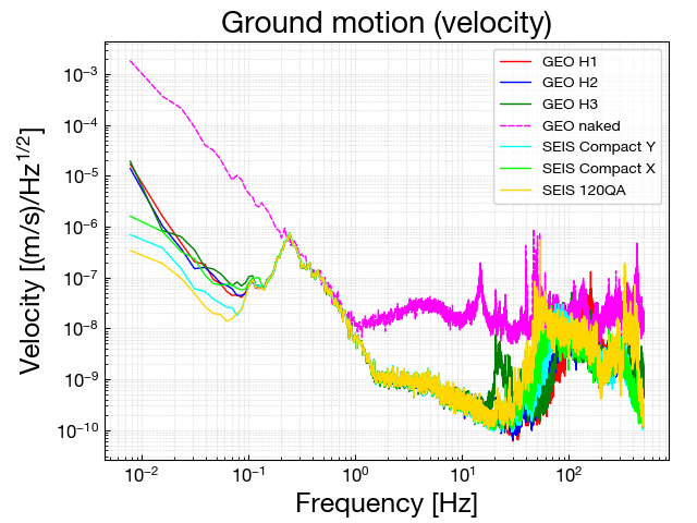
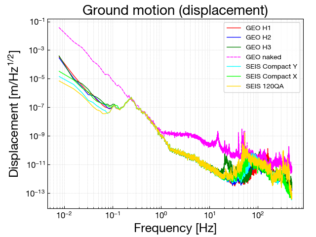
- Geophones' parameters are adjusted so that the geophones and the seismometers have same spectra of ground motion in the range of 0.1-10 Hz
-
In this parameter estimation, the seismometers are regarded as reference because of
- broadband flat response (0.01-10 Hz)
- the fact that the 3 seismometers have a consistent level of displacement spectrum even with a simple calibration method
- Estimated geophone parameters
| S/N | Generator const. [V/(m/s)] | Damping ratio (nominal) | Damping ratio (estimated) | f0 (nominal) [Hz] | f0 (estimated) [Hz] | |
| GEO H1 | #11 | 282.26 | 0.299 => | 0.34 | 0.99 => | 1.07 |
| GEO H2 | #12 | 282.30 | 0.276 => | 0.315 | 0.99 => | 1.065 |
| GEO H3 | #13 | 286.47 | 0.293 => | 0.27 | 1.0 => | 1.31 |
-
Notes:
-
The pre-amp circuit (JGW-D1301466) seems to have a gain of 375.53 * 5.0 / 2 = 938.8, not 375.53 * 5.0 = 1877.7
- Sekiguchi-san's PhD thesis (p.114 in JGW-P1504155) missed to mention that the differential opamp at the final stage outputs a half amplitude of the input voltage
- You can check that in the data sheet of the differential opamp => product page
- Trillium Compact: 749.1 [V/(m/s)] (measured, cf. JGW-D1707542)
- Trillium 120QA: 1202.1 [V/(m/s)] (nominal, cf. JGW-T1707554)
-
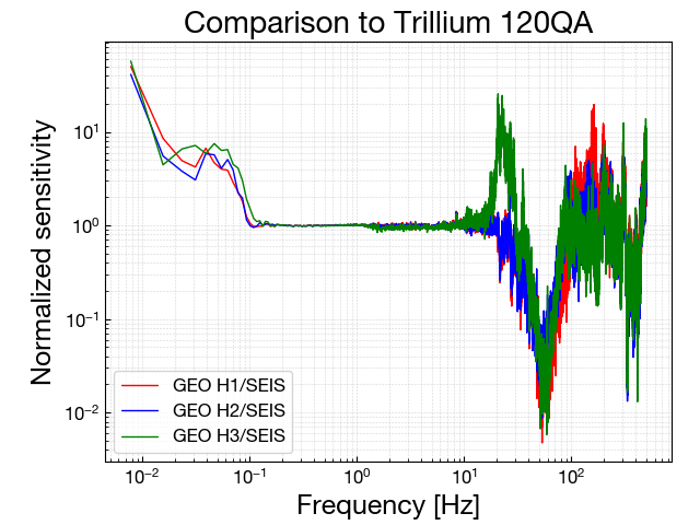
The disagreement between the geophones and the seismometers in heigher frequency (> 10 Hz)would come from the accuracy of the pod assembling, the base plate where the geophones are put and so on
- This disagreement may not be a problem because the frequency band above 10 Hz is out of the range for the geophone to monitor velocity of the IP stage
-
The pre-amp circuit (JGW-D1301466) seems to have a gain of 375.53 * 5.0 / 2 = 938.8, not 375.53 * 5.0 = 1877.7
Noise measurement
-
Sensor noises are measured using the conversion efficiency obtained above
- Putting the geophone pod upright makes the internal proof mass fixed
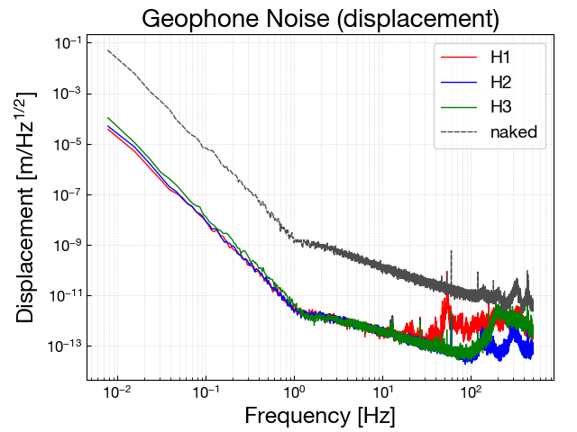
- Geophone sensor noise
| Displacement noise [m/Hz1/2] @ 0.1 Hz | Displacement noise [m/Hz1/2] @ 10 Hz | |
| GEO H1 | 8 x 10⁻⁹ | 3 x 10-13 |
| GEO H2 | 8 x 10⁻⁹ | 3 x 10-13 |
| GEO H3 | 1 x 10⁻⁸ | 3 x 10-13 |
- Accelerometers which we "were" going to use for Type-A are expected to have a noise level of ~ 3 x 10⁻⁸ m/Hz1/2 @ 0.1 Hz (according to a measurement in TAMA?)
- The geophones now we have can achieve smaller noise level than the expected accelerometers
Current situation
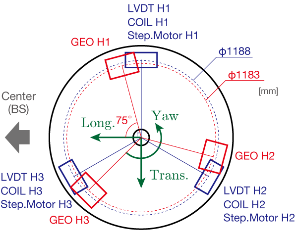
- Now the geophone pods are installed on the IP of Type-A ETMX
- The response we obtained needs to be implemented into the input filter on the digital system
- Sensor configuration on the ETMX IP: