[S.Nagano, Kokeyama, Nakano, K.Nagano]
We adjusted coil balance of IMC suspensions, i.e. MCi, MCo, and MCe.
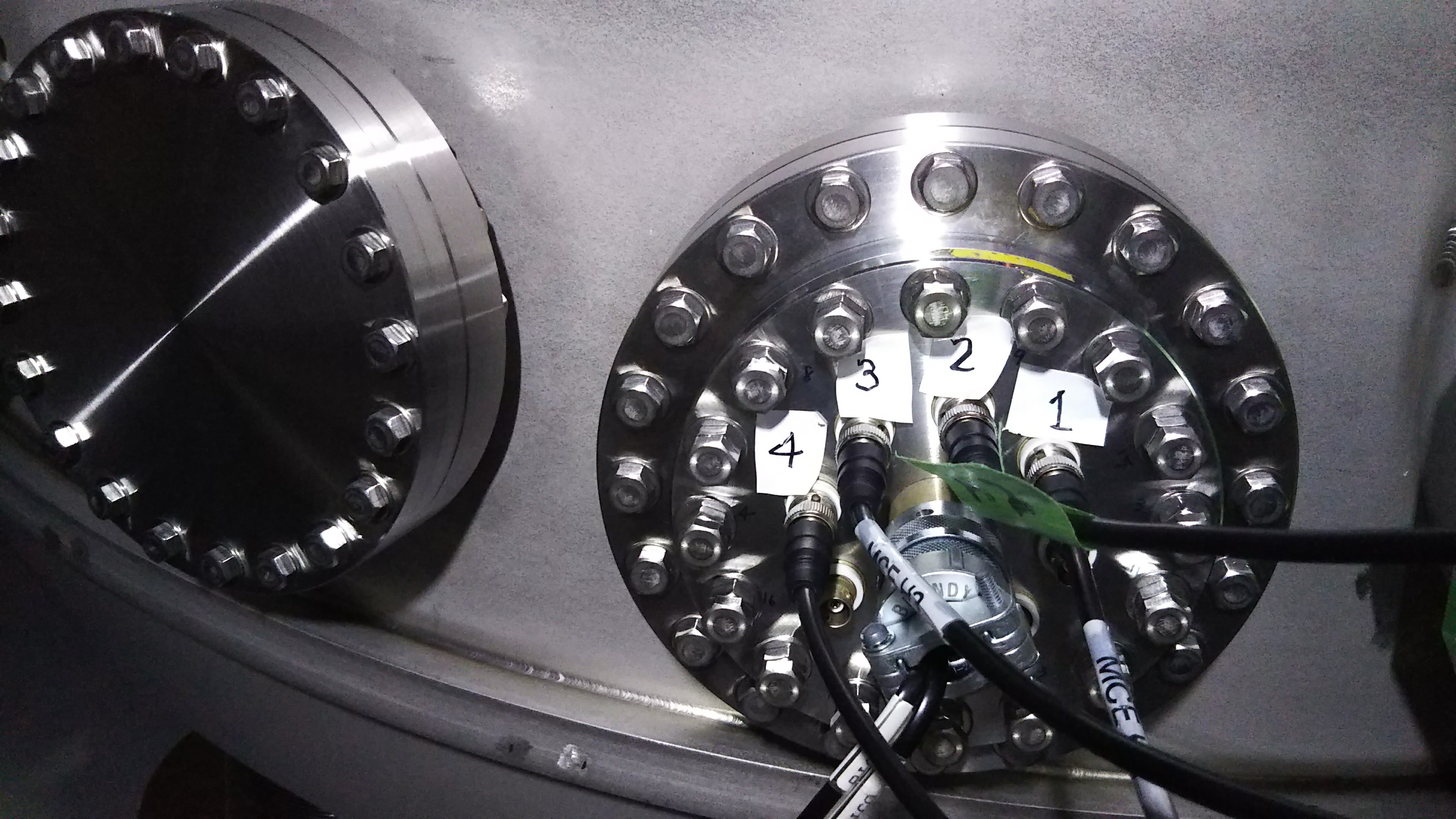
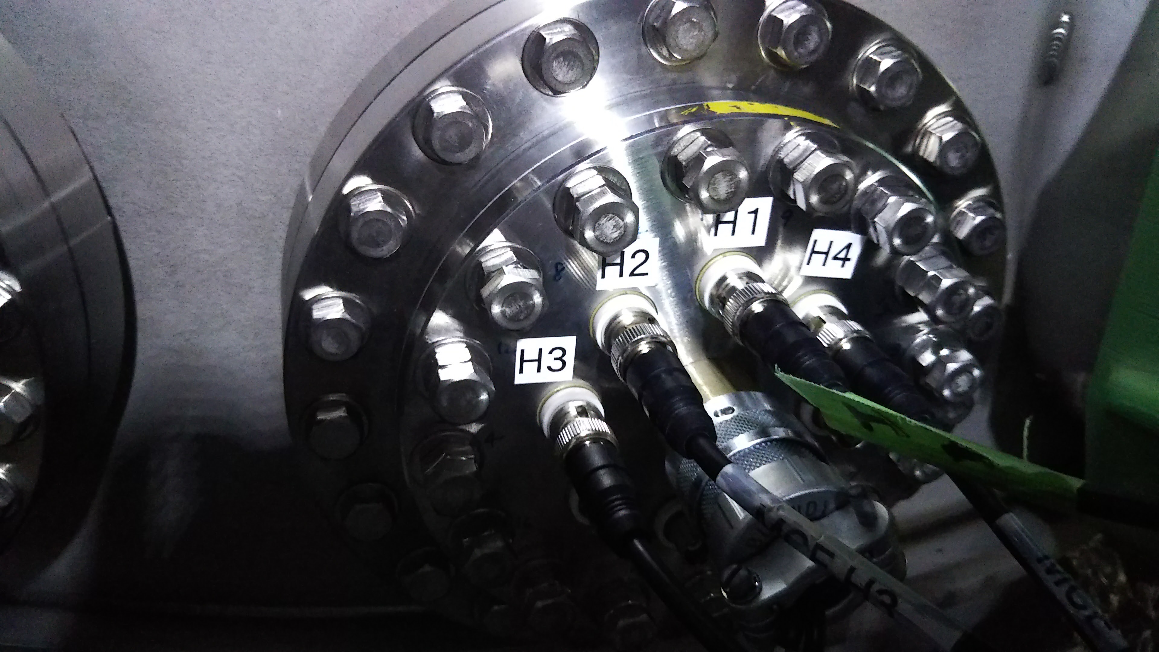
At first, the sign of each coil-magnet actuators of each IMC suspension were checked.
We judged the sign by exciting the actuator one by one and seeing the oplev pitch and yaw signal.
As a result, it was decided that the gain sign of coils (H1, H2, H3, H4) of MCi, and MCo, and MCe should be (+, +, +, +), (+, -, +, -), and (-, +, +, +), respectively.
This means that MCi coils were installed alternately while MCo coils were not.
During this measurement, we noticed that the sign of MCe was strange.
This might be because the cabling connection was wrong (maybe H1 and H3 (or H2 and H4) were flipped)
The detail of this measurement will be reported later.
Then the coil balance was adjusted.
Before the adjustment was started, we installed aluminum foil windshield for each oplev pylons to reduce the noise of the oplevs which will be used to adjust the coil balance.
The storategy adjusting the coil balance was as follows:
1. Apply voltage (sine wave, 20 Hz) to H1 and H2 and adjust gain of H2 and reduce the pitch motion (the signal was observed with power spectrum)
2. Apply voltage (sine wave, 20 Hz) to H2 and H3 and adjust gain of H3 and reduce the yaw motion
3. Apply voltage (sine wave, 20 Hz) to H3 and H4 and adjust gain of H4 and reduce the pitch motion
4. Apply voltage (sine wave, 20 Hz) to H4 and H1 and adjust gain of H1 and reduce the yaw motion
5. Apply voltage to all coils and adjust the gains a bit to reduce the yaw and pitch motion.
(Ideally, the coil balance could be adjusted in the third step. However, the residual unbalance was left. Thus we need the fourth and fifth steps to reduce the unbalance more.)
Finally, the coil coupling was reduced by about a factor of 10 compared with before the adjustment.