[Nagano, Nakano]
We measured some noise spectrums and transfer functions which are related with FSS to investigate the noise levels on FSS.
The measurement settings were described as follows.
(Plots with obtained data were reported later.)
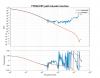
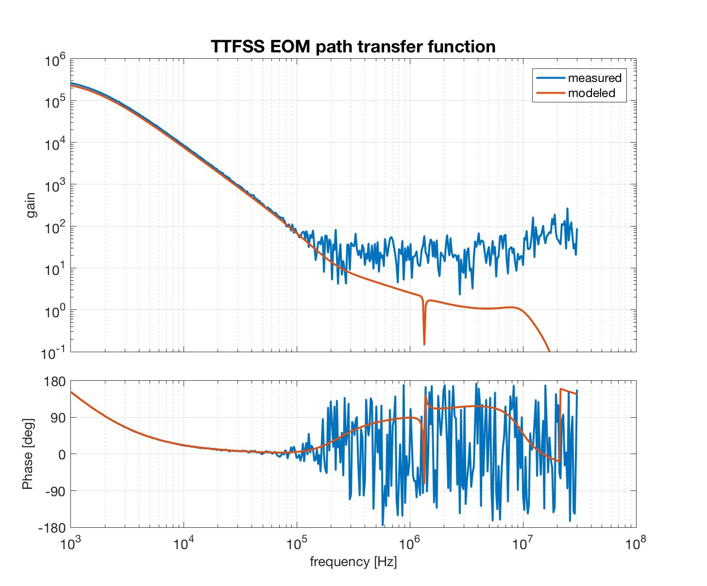
Measurement 1: TTFSS trasfer function of EOM path
At first, we measured the transfer function of TTFSS, from Common OUT1 to EOM OUT, using network analyzer (NA).
To attenuate the output signal, a handmade attenuator (-60 dB) was put between EOM OUT and NA.
Since the NA excitation signal setting resolution was too large, we put a -30 dB attenuator (mini circuit product) at NA output port.
The TTFSS gains were minimum, that is Common Gain and Fast Gain were -10 dB, to avoid saturation.
Please note that the measured data was normalized by data measured with only BNC cables and the handmade attenuator.
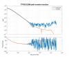
Measurement 2: TTFSS trasfer function of PZT path
Second, the transfer function of TTFSS, from Common OUT1 to PZT OUT, with NA.
In this measurement, the attenuators used in the above measurement were not used.
The gain setting was Common Gain and Fast Gain were -10 dB, the same as the 1st measurement.
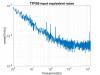
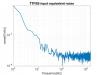
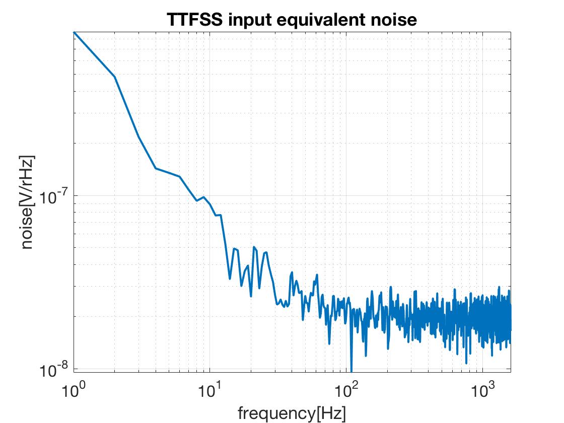
Measurement 3: TTFSS input equivalent noise
Third, we measured the noise spectrum of TTFSS circuit with a spectrum analyzer.
The measured point was PZT out.
The PD input was terminated with 50 Ohm, while LO was input.
The TTFSS gains were maximum, that is Common Gain and Fast Gain were 30 dB.
Since the gain was large, we had to tune the offset to avoid the saturation.
Measurement 4: MC servo + Offset circuit input equivalent noise
Fourth, the noise spectrum of MC servo (from INPUT1) and the offset circuit for double pass AOM (DPAOM).
The aim is this measurement is investigation of the offset circuit for DPAOM.
The measured point was OUTPUT of offset circuit.
The MC servo INPUT1 was terminated with 50 Ohm.
Common Mode Servo setting was as follows; INPUT1 gain was -32 dB, compensation was off, slow boost was off.
In this measurement, the gain of MC servo was so small that we can see the noise level of the offset circuit for DPAOM.
Measurement 5: Input equivalent noise of MC servo with Slow Output Offset
Finally, after this measurement, we noticed that in the Slow path of MC servo there is slider (Slow Output Offset) to input offset on SLOW OUT and the Offset can be used instead of the offset circuit whose noise was measured above.
Therefore, we measured the noise level of MC servo with 7.5 V of Slow Output Offset.
The other Common Mode Servo setting was as follows; INPUT1 was terminated with 50 Ohm, INPUT1 gain was 31 dB, compensation was on, slow boost was off.
Again, the result plots of the above measurements were reported later.