With Hirata-san, Enzo.
Today:
- We checked the real-time model to see if it was still OK after Okutomi-san's modifications. It wasn't running and we had to start it, but it seemed fine.
- We added an extra pair of conductors for the BF yaw picomotor to the adapter for the IM picomotors. We anchored the new section of cable inside the BF with a length of kapton-coated copper wire and connected it to the yaw pico.
- We tried to connect the BF LVDT using the adapter that Hirata-san had made, but realized we couldn't tell which of the pairs of wires were the input, output and actuation coils. We measured the resistances to help identify them: 78.4, 109.2, 201.6 ohm.
- We tried to connect the stepper motor and again realized that we needed more information: the wires are labelled black, white, green and brown, but we need to map this to A1, A2, B1 and B2 for the driver.
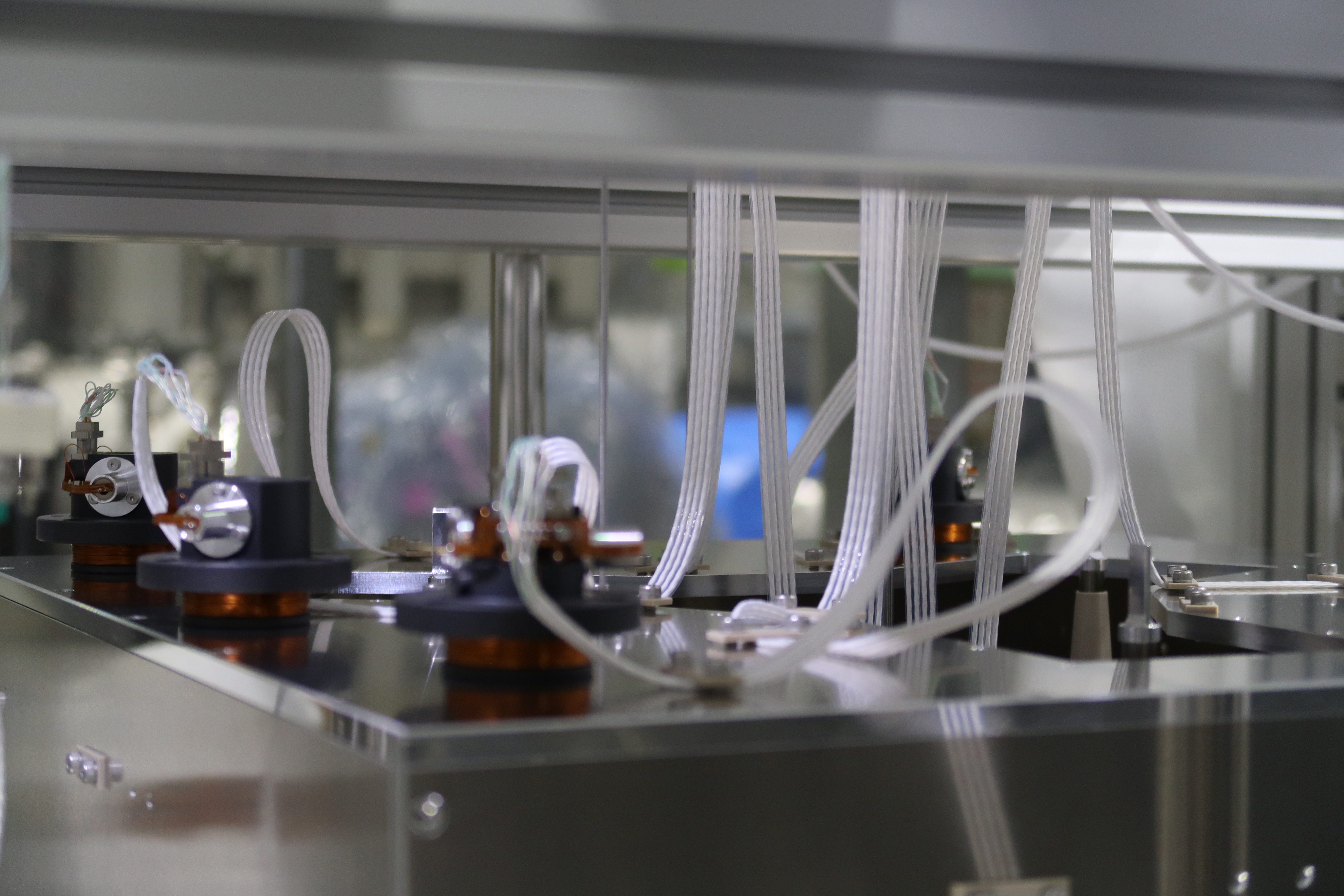
- We added 5 additional OSEM cables ("Type 5") for the IM OSEMs (Fabian had previously added one as a test of the cable clamps).
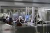
- We laid out 6 wide-mouthed OSEMs on the top of the IRM (see photo) and connected them up as H1=27, H2=28, H3=29, V1=30, V2=31 and V3=32. (We did not attempt to install them around the flags yet.)
- We connected them to the vacuum feedthrough with 6 PI-Flange cables ("Type 1"). (The circuit diagram also calls for extension cables ("Type 3") but we left them out for now because we don't need the extra length yet and they would just get in the way.)
- We put a sticky mat on a duckboard (sunoko) on the second floor near the top of the ladder, to minimize dirt being taken up on shoes. (We want to put two more sticky mats downstairs to use everytime we go up the step ladders, but the duckboard doesn't work very well because the sticky mats don't stick to it, and sticking a mat directly to the floor near the assembly frame will be a problem, so we're trying to think of a better plan.)
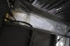
- We noticed that water was dripping on the floor in the +X, +Y corner of the cleanbooth. We investigated and found that water was pooling on the plastic sheet between the last filter unit and the +Y side of the clean booth, and then dripping down (see photo). That piece of sheet is covered by a corrugated plastic roof, so there must be a leak in that roof as well.
Tomorrow we will install the feedthrough adapters on the outside of the feedthrough, connect the cables to the sat amps and do a noise test of the 6 IM OSEMs. We will also run in-air cables for the picos, stepper and LVDT, and (if we can find the right information) connect up the stepper and LVDT.