Thursday, with Fabian and Liu-kun.
Today:
- Because we had already taken a lot of trim mass off the top and needed to take 92 g more (see klog 2087), we decided to start by removing the 293 g of thin trim masses from the bottom and add ≈208 g on top.
- We reverted to the original baseline configuration of trim masses for the top (with a 355 g or 370 g at each corner plus a few 75 g or 37 g), then added 2x75 g at the +X,+Y corner, 75 g at the -X, -Y corner, and moved 38 g from +X,+Y to -X,-Y, for a net increase on the top of 3x75 = 225 g and a net decrease overall of 293-225 = 68 g. See "BS Test Hang" album in Google Photos for pictures of the final mass configuration.
- We measured the heights of the high and low sides of the keystone and found the average had gone up to 66.0 mm, which is a bit more than we were expecting (target 65.5) but close enough.
- We measured the frequency by timing a few periods and got 0.58 (average of three measurements by different people). This is consistent with what we saw yesterday, and still higher than Hirata-san's 0.4 Hz.
- We checked the pitch of the dummy BS with the optical lever and the roll of the IM with the bubble level, and added M8 washers to the trim mass to set the dummy BS to the correct downward pitch and make the IM level in roll. (We don't want to use the IM picomotors yet because we can't see them, and if we accidentally use up their range it will be awkward.)
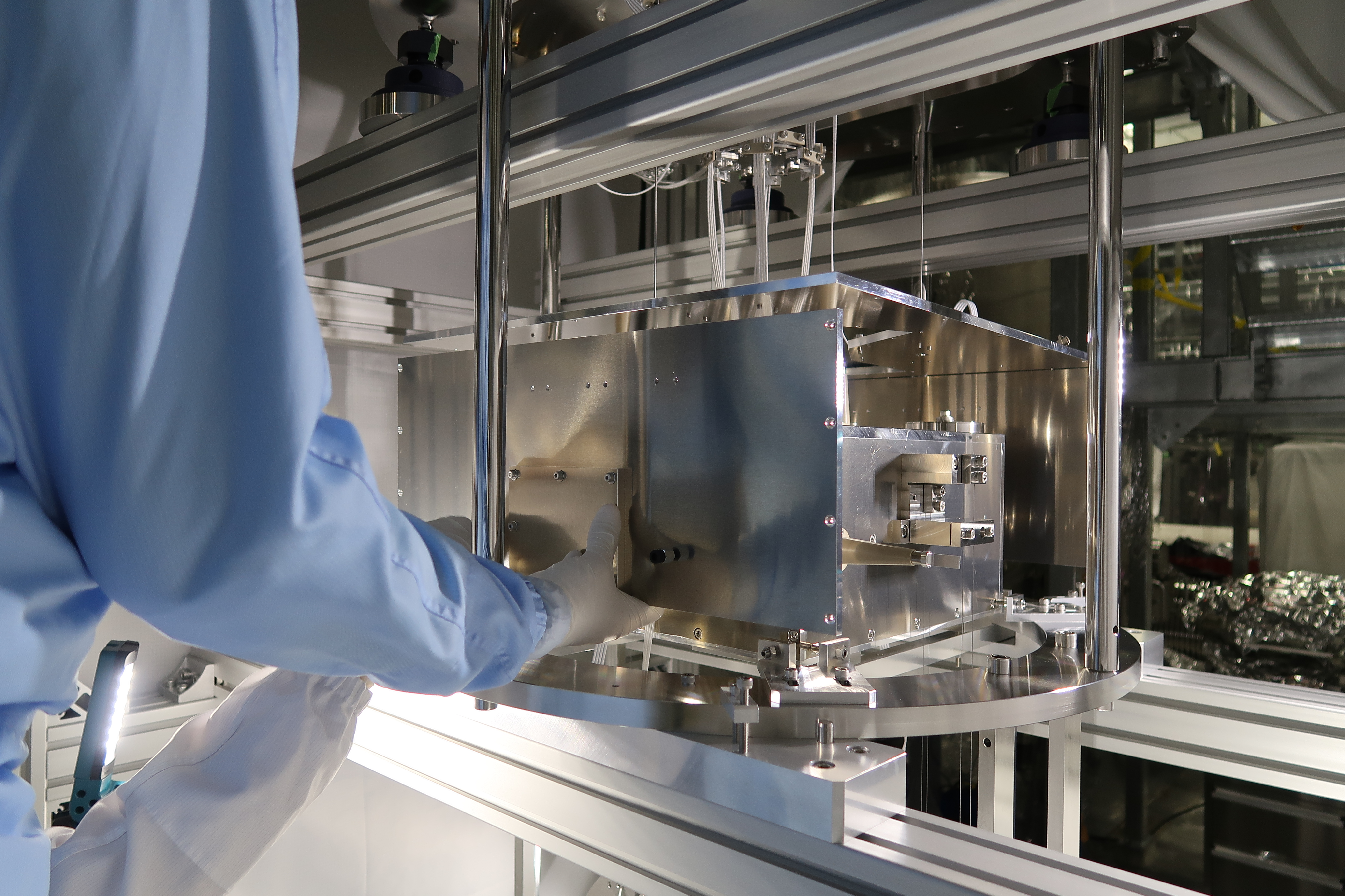
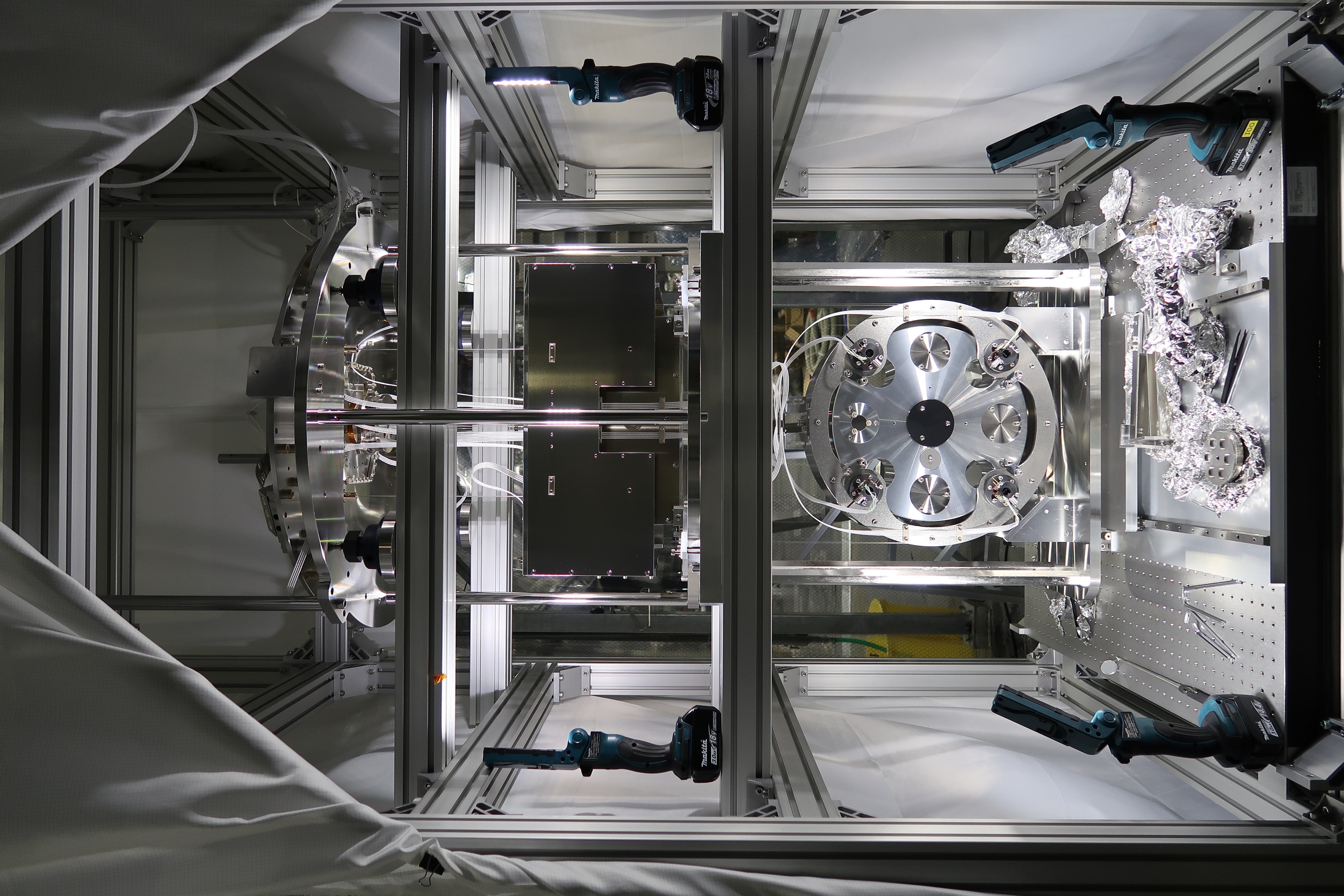
- We constructed the rest of the IRM, starting with the front and back plates. (See photo.)
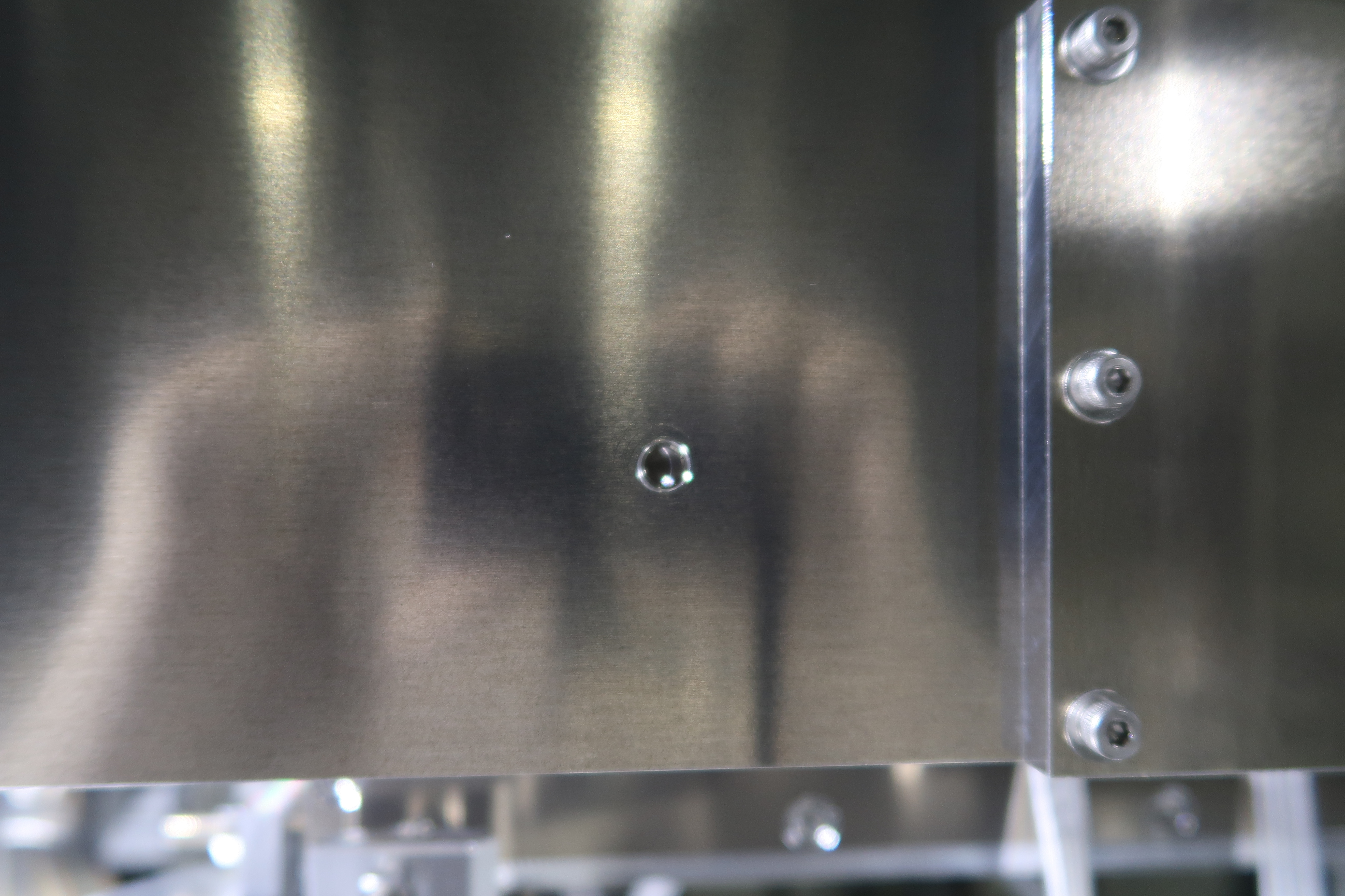
- We adjusted the IRM rod holders to set the pitch and height of the IRM so that the lock screw holes on the IRM lined up with the lock screw receptacles on the IM. (See photo.) Unfortunately there are no transverse or yaw adjustments and we found that there was a transverse misalignment of ≈1-2 mm on the +X side that we couldn't correct. (See photo.) This may be connected with the offset of the IM-BF rod, although the direction the rod appears to be displaced relative to the BF is mostly -X and only a bit of -Y, whereas the IM has a significant offset in -Y. (It may also have a ±X offset but that's not easy to see and would need a very tricky measurement to confirm.)
- The misalignment of the lock screws may or may not be a problem. It means that if the lock screws are inserted, the IM and IRM will be forcibly aligned to a common center, which may mean that the OSEMs bump into the flags if they have been adjusted to accomodate the misalignment. With the new wide-mouth OSEMs, we may be lucky. If not, we will have to avoid using these lock screws and lock the IM and IRM independently.
The next step will be to mount the IM OSEMs and run cabling for them as well as for the BF picomotor, stepper motor and LVDT. We also need to make extensions for the RM OSEM cables, which are too short. Once all that is done we can take transfer functions of the full payload.
This was Liu-kun's last day - thanks to him for the help this month.

