With Hirata-san.
- We installed the oplev optics and began the alignment.
- We routed a 20 m orange power cable from the rack and connected it to the SLD with a gray cable supplied by AOS.
With Hirata-san.
As a temporary measure, I multiplied with a factor of 100 some amplification factors in two of the oplev medm screen. This with the aim to be able to see clearly where the oplev dot indicator is on the screen:
I did not commit these changes in the SDF.
Today I continued aligning the oplev optics.
Yesterday, after putting the breadboards with the optical components in place, it was relatively easy to get the light onto the QPD. This afternoon, however, I checked the position of the reflection point on the SRM mirror. It was too far away from the center. It was very close to the edge of the small SRM mirror. Then, I did the following:
Tomorrow I aim to check the position of the length sensing QPD with respect to the lens, and calibrate the readout of the QDPs in terms of displacement. We should also build a cover.
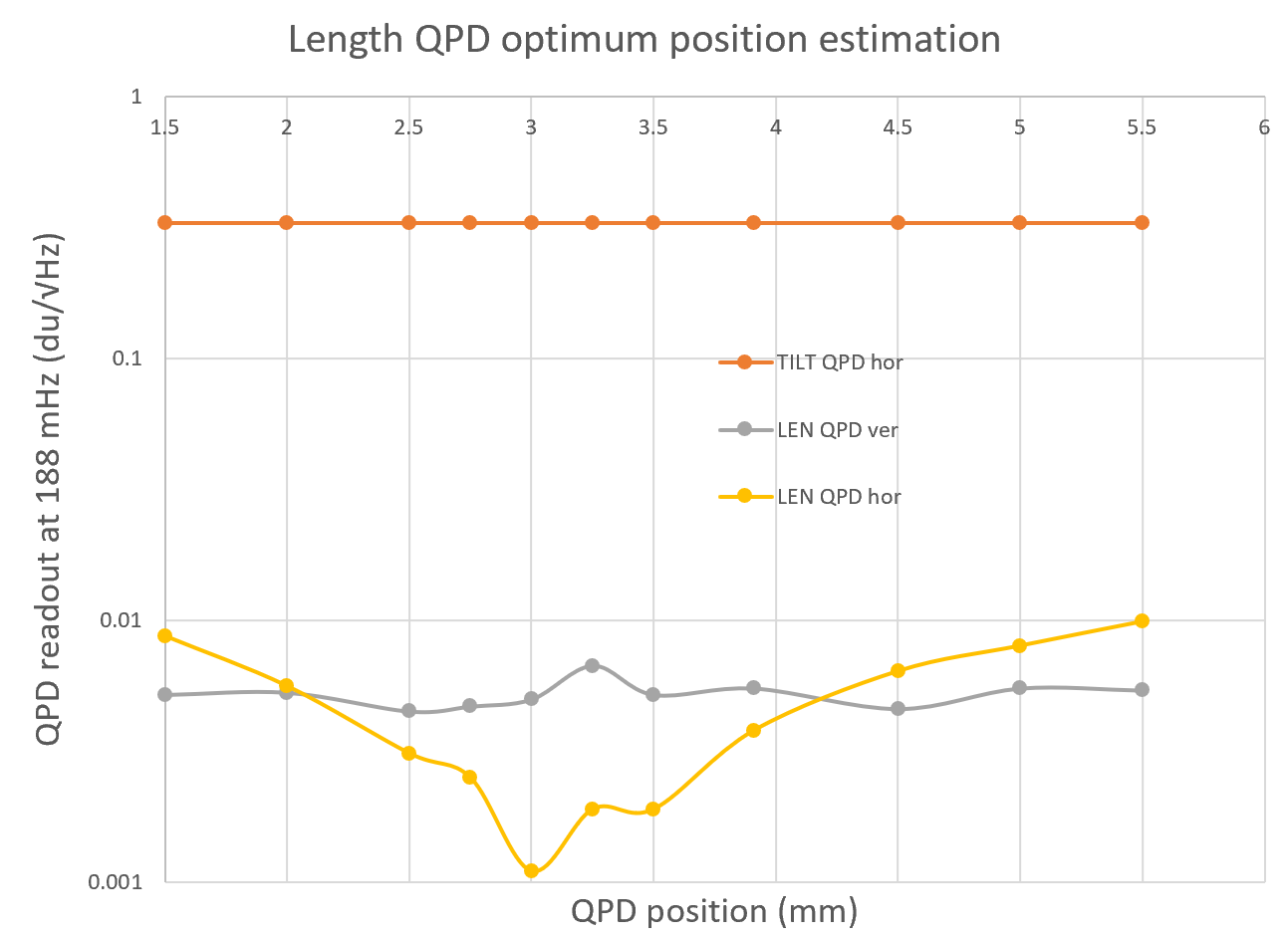
Today I checked whether the length sensing QPD is in a suitable position with respect to the lens. I applied a sinusoidal actuation at 200 mHz in TM-Y and checked the ouput in the length sensing QPD. There was a relatively small coupling. I moved the QDP along the optic axis to see whether the coupling incresed or decreased, but it seemed to remain the same. I'll continue with this test tomorrow.
With Hirata-san.
The details of the work here briefly described will be given later.
With Hirata-san.
See pictures in SRM Remedying Work album.
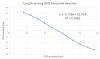
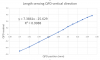
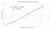
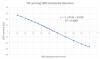
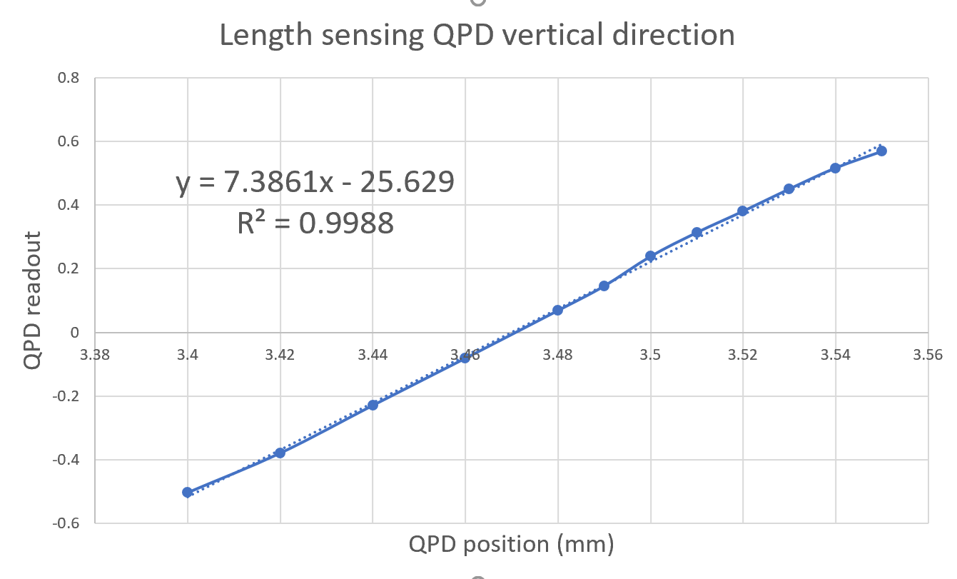
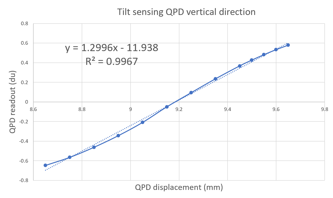
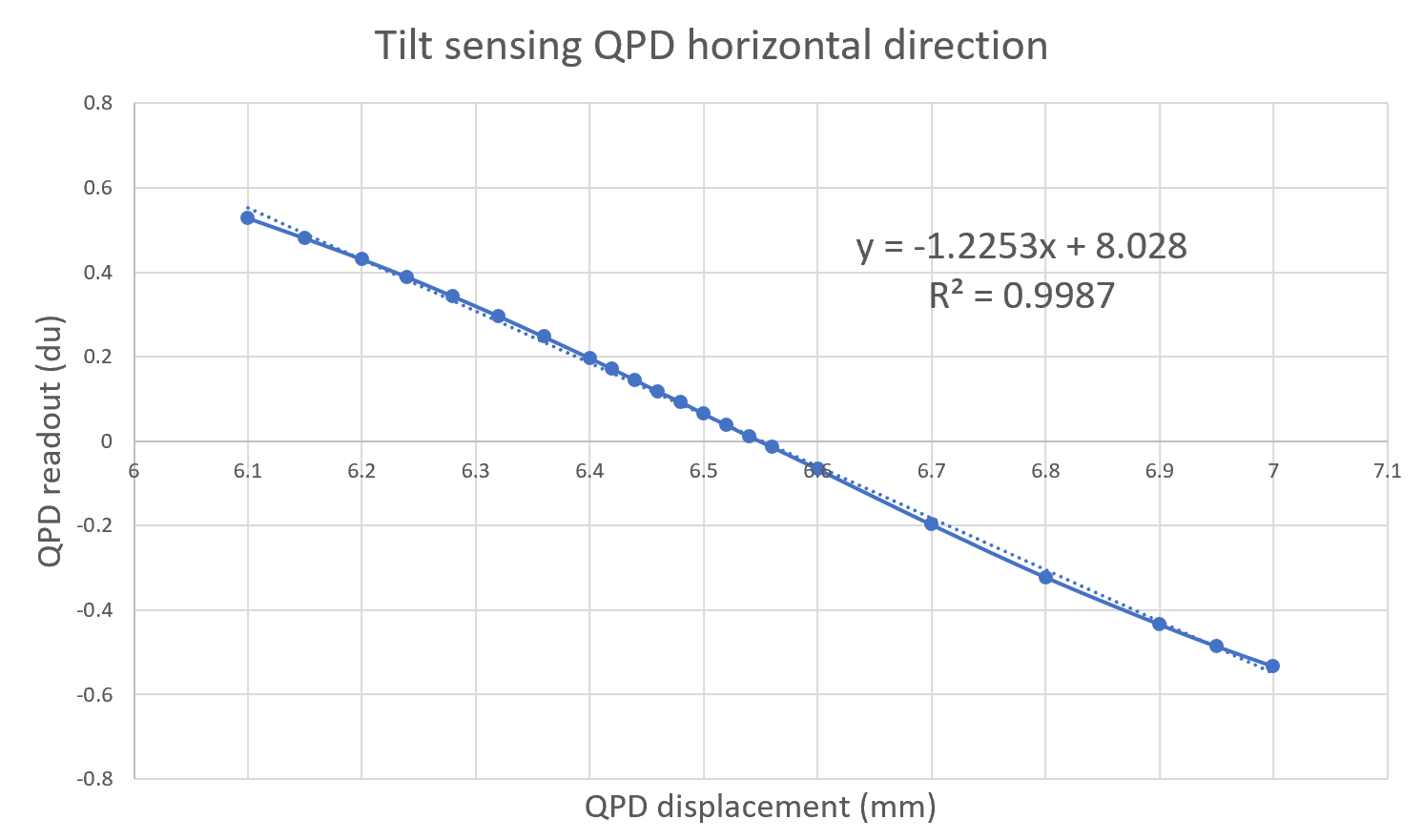
| QPD parameter | calibration factor (du/mm) | Linear range (mm) |
| LEN VER | 7.39 | [ 3.40 , 3.55 ] |
| LEN HOR | -6.73 | [ 8.14 , 8.34 ] |
| TILT VER | 1.30 | [ 8.65 , 9.65 ] |
| TILT HOR | -1.22 | [ 6.10 , 7.00 ] |
With the calibration factors obtained, I put followings
K1:VIS-SRM_TM_OPLEV_LEN_VER_GAIN: 1/7.39*1000 = 135.318 [um/counts]
K1:VIS-SRM_TM_OPLEV_LEN_HOR_GAIN: 1/6.37*1000 = 148.599 [um/counts]
K1:VIS-SRM_TM_OPLEV_TILT_VER_GAIN: 1/1.3*1000 = 749.230 [um/counts]
K1:VIS-SRM_TM_OPLEV_TILT_HOR_GAIN: 1/1.22*1000 = 819.670 [um/counts]
which would calibrate K1:VIS-SRM_TM_OPLEV_{LEN, TILT}_{VER, HOR}_OUT to the beamspot positions at the QPD planes, in microns.
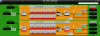
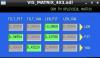
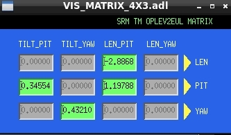
Using old length data from 7952, I obtained the OPLEV2EUL matrix as shown in Fig. 1. To reproduce, consult Eqn. (20) in JGW-T2112874 or visit the notebook in /kagra/Dropbox/Subsystems/VIS/vis_commissioning/srm/notebook/sensing_matrices/optical_lever.ipynb
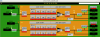
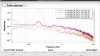
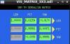
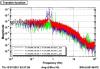
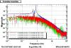
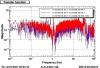
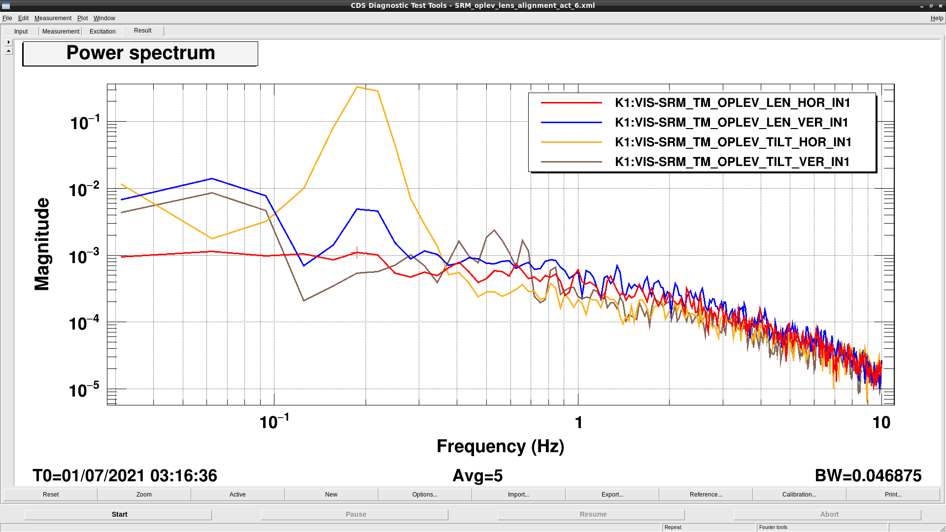
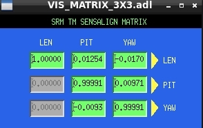
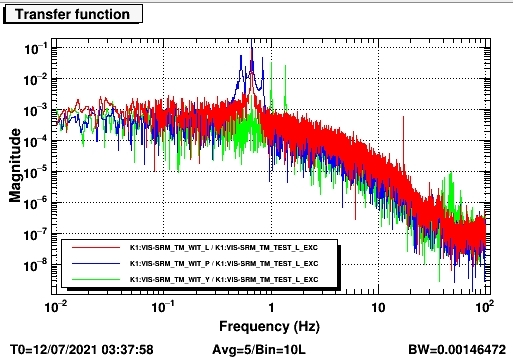
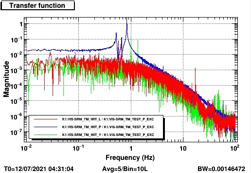
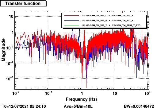
I reverted the actuation matrix EUL2OSEM to 0.25s (for L) and 1s and -1s for (P and Y) and measure transfer functions. The readouts show a very high noise floor which is normal given the optical lever isn't covered with windshields. Nevertheless, Diagonalization was straightforward. And I obtained SENSALIGN matrix as shown in Fig. 2. Transfer functions measurements are shown in the following figures. Yaw transfer function plots were missing due to some unknown bugs, I will have to measure them again later. Nevertheless, the coupling ratios P/Y and L/Y are at the 1e-4 level at yaw resonances (Fig. 5).
Note that the matrices have very low commitments, as I might intercalibrate them with IP readouts. Also, I have not probably L2P coupling as I will use the IP to do so but I am doing minor adjustments at the IP level. But sanity check shows good inter-calibration with the IP.
I just added a new column to the table writing explicitly the size of the linear range:
| QPD parameter | calibration factor (du/mm) | Linear range (mm) | Linear range (µm) |
| LEN VER | 7.39 | [ 3.40 , 3.55 ] | ±75 |
| LEN HOR | -6.73 | [ 8.14 , 8.34 ] | ±100 |
| TILT VER | 1.30 | [ 8.65 , 9.65 ] | ±500 |
| TILT HOR | -1.22 | [ 6.10 , 7.00 ] | ±450 |
