With Hirata-san and Miyo-kun.
See pictures in album PR3 Remedying Work.
Summary: we assembled the payload, released the system and measured four IM transfer functions. It seems that the system is hanging free, but OSEM V1 is out of range.
- We took pictures of the outer clamps we removed yesterday. The scars are superficial compared to the thickness of the tungsten wire, which is 600 um. See this picture and this other one.
- In the coil bodies, we set the push screw lengths to 8 mm per the 3D-CAD. They were mostly close to 8 mm already.
- We made sure the RM was supported from underneath and that the mirror was locked to the RM.
- We put back the coil bodies onto the RM. The pull screws were properly tightened.
- We released the mirror and the RM completely to let them hang free.
- We put back the outer clamps, made sure the tungsten wires were in the grooves and tightened the screws with a 2 Nm torque.
- We inspected the position of the mirror magnets with respect to the coil bodies. See the pictures. The all look located at the lower part of the cavity. I cannot remember them being as low before. This condition might be due to the clamping of the piano wires in the locating clamps. For the sake of the safety of the magnet standoffs, maybe we should tilt the coil bodies slightly to have more clearance between the coil bodies and the magnets.
- For the sake of safety we locked the mirror and the RM.
- We put the missing H2 OSEM magnet in its pedestal with the north pole out. This is a new magnet. The old was had been chipped.
- We put back the side panels of the IRM.
- We put back the H2 and H3 OSEM flags in place.
- We released the whole payload and the BF from the security structure.
- We checked the position of the horizontal OSEMs flags within their cavities: They were in a way that suggested a lot of negative pitch. H1 and H2 up and H3 low. One of them was closely touching the body. It's interesting to point out that, as reported above, at the mirror, the magnets are at the lower part of the coil body cavities, position which may indicate the mirror has a lot of negative pitch with respect to the RM. However I don't know whether the two are related.
- We used the IM picomotor to bring the horizontal OSEM flags closer the cavity centers (moving pitch closer to zero) until they look alright judging by visual inspection.
- However, V1 is out of range.
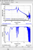
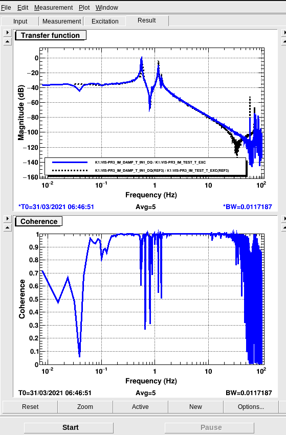
- We measured transfer functions in IM L, T, Y and R. All of them look fine. The system seems to be hanging free. It's worth saying that the one for IM-L has a low coherence below 100 mHz and an unexpected shape above 30 Hz with respect to the reference in the dtt file. See picture attached to this report.