Reports 1-1 of 1 Clear search Modify search
VIS (PR3)
fabian.arellano - 20:47 Tuesday 23 March 2021 (16310) Print this report
Preparation for testing the procedure to glue the piano wire at the locating clamps in the IM.

With Hirata-san.

See pictures in album PR3 Remedying Work.

Today we did two separate but related tasks.

  • We mounted a spare wire clamp assembly on a table and we hung a light load but we haven't tightened the screws yet. See this picture. We will test the procedure in this set up.
  • Using thickness gauges we measured the gap between the two components of the locating clamps (see this notebook page). The gap size is between:
    • +Y, -X, lower side: (100, 120) µm
    • +Y, -X, upper side: (170, 180) µm
    • -Y, -X, lower side: (80, 90) µm
    • -Y, -X, upper side: (130, 140) µm
    • We had to partially disassemble the IRM to do these measurements.
    • As suggested by these values, the clamps pieces are are tilted with respect to each other because the gaps are not uniform.
    • The thickness of the clamped wire is 200 µm.
Comments to this report:
fabian.arellano - 16:39 Wednesday 24 March 2021 (16318) Print this report

With Hirata-san.

See pictures in album PR3 Remedying Work.

Today we finished measuring the gaps in the locating wire clamps for the piano wire using thickness gauges. See this notebook page. The first four lines were already reported in a previous entry but I write them here for the sake of completeness:

  • +Y, -X, lower side: (100, 120) µm
  • +Y, -X, upper side: (170, 180) µm
  • -Y, -X, lower side: (80, 90) µm
  • -Y, -X, upper side: (130, 140) µm
  • +Y, +X, lower side: (80, 90) µm
  • +Y, +X, upper side: (140, 150) µm
  • -Y, +X, lower side: (70, 80) µm
  • -Y, +X, upper side: (120, 130) µm.

We also finished setting up the clamps for the gluing test:

  • We hung a dummy load. As can be seen in the pictures in the album, we were very careful to accomodate the wires within the grooves.
  • We adjusted the piano wire locating clamps to have gaps sizes within (90, 100) µm on the left and (20, 30) µm on the right. See this notebook page.
  • We adjusted the screws very gently and we were not able to achive larger gaps as the ones in the PR3 clamps. Bigger gaps would have only been achieved with the screws totally loose.
  • We also became acquainted with some tool to deliver the adhesive at the lower side of the clamps. See pictures in the album.

This afternoon we received all the material we need for the test. Therefore, tomorrow we will proceed.

fabian.arellano - 17:02 Thursday 25 March 2021 (16331) Print this report

With Hirata-san.

See pictures in album PR3 Remedying Work.

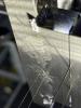
Summary: we had the impression not much adhesive went into the gap close to the wires.

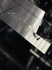
Because the gap we achieved yesterday in the clamps was smaller compared with the ones we have in PR3 clamps, we decided to put spacers to make it bigger.

  • We used folded aluminium foil 50 um thick.
  • When measured with the caliper the spacers were about 120 um.
  • The adhesive is already very thick after one hour of preparing it and becomes harder to handle for this application.
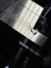
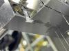
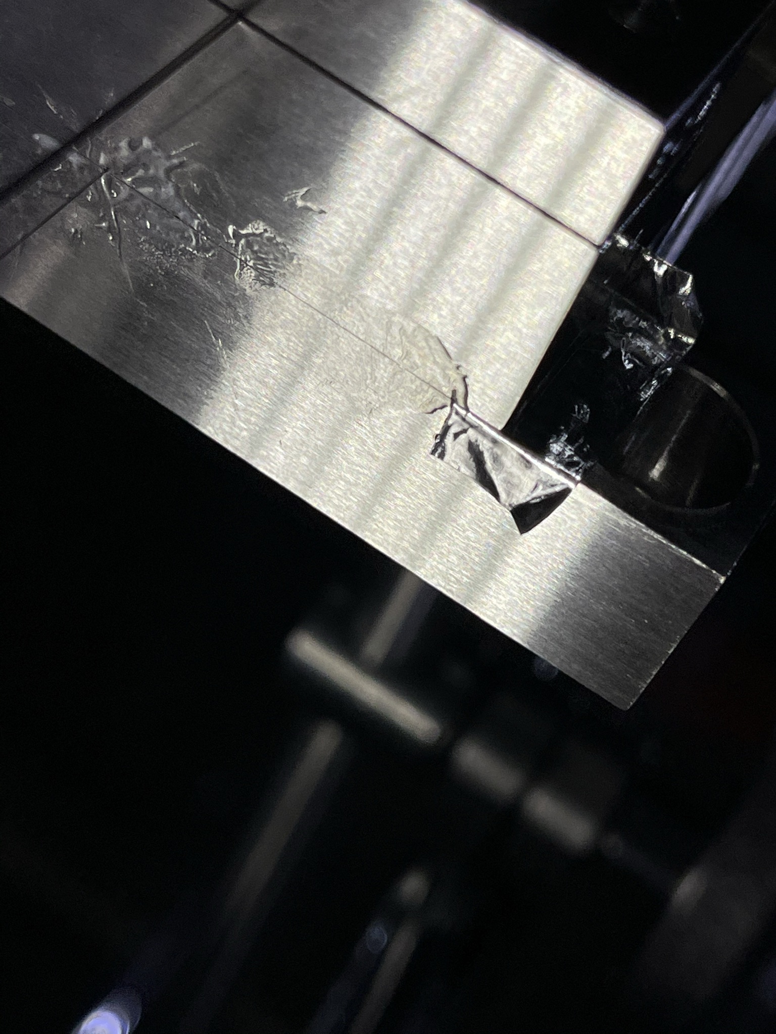
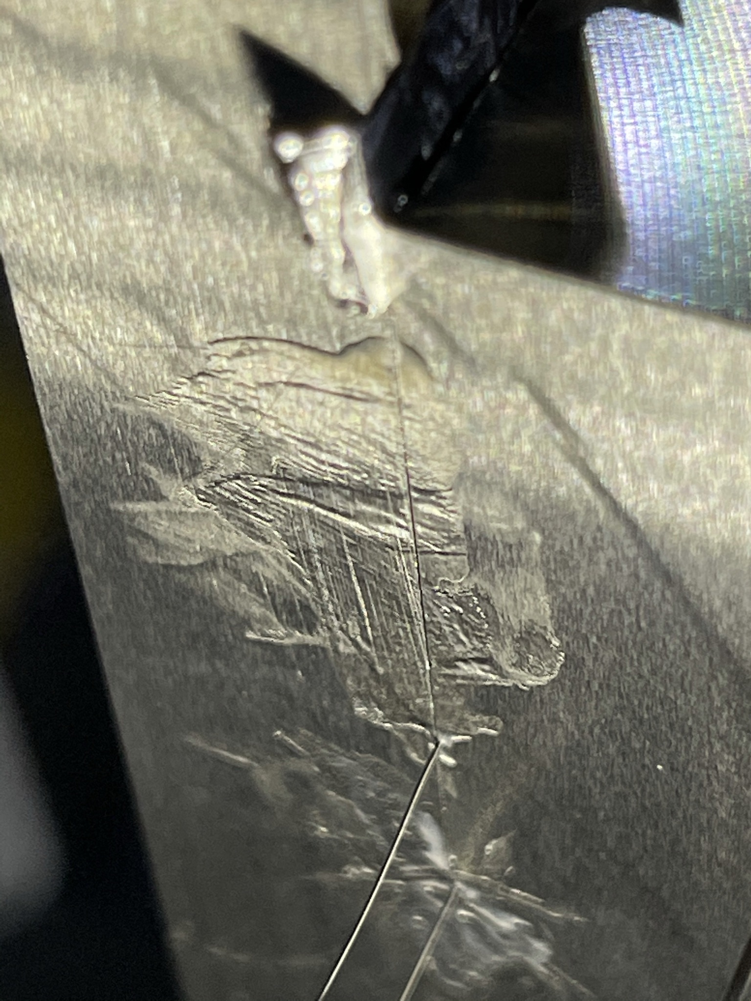
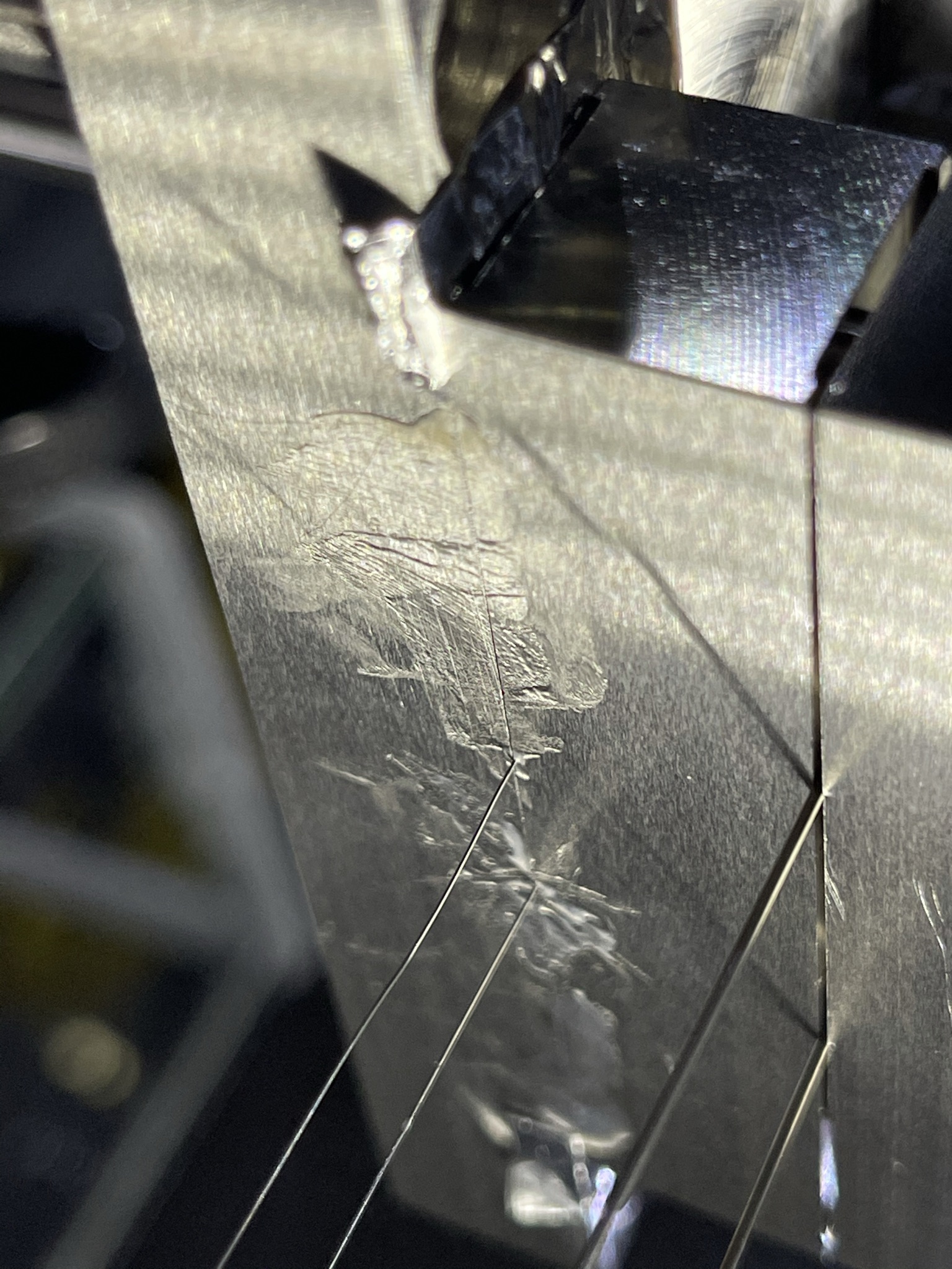
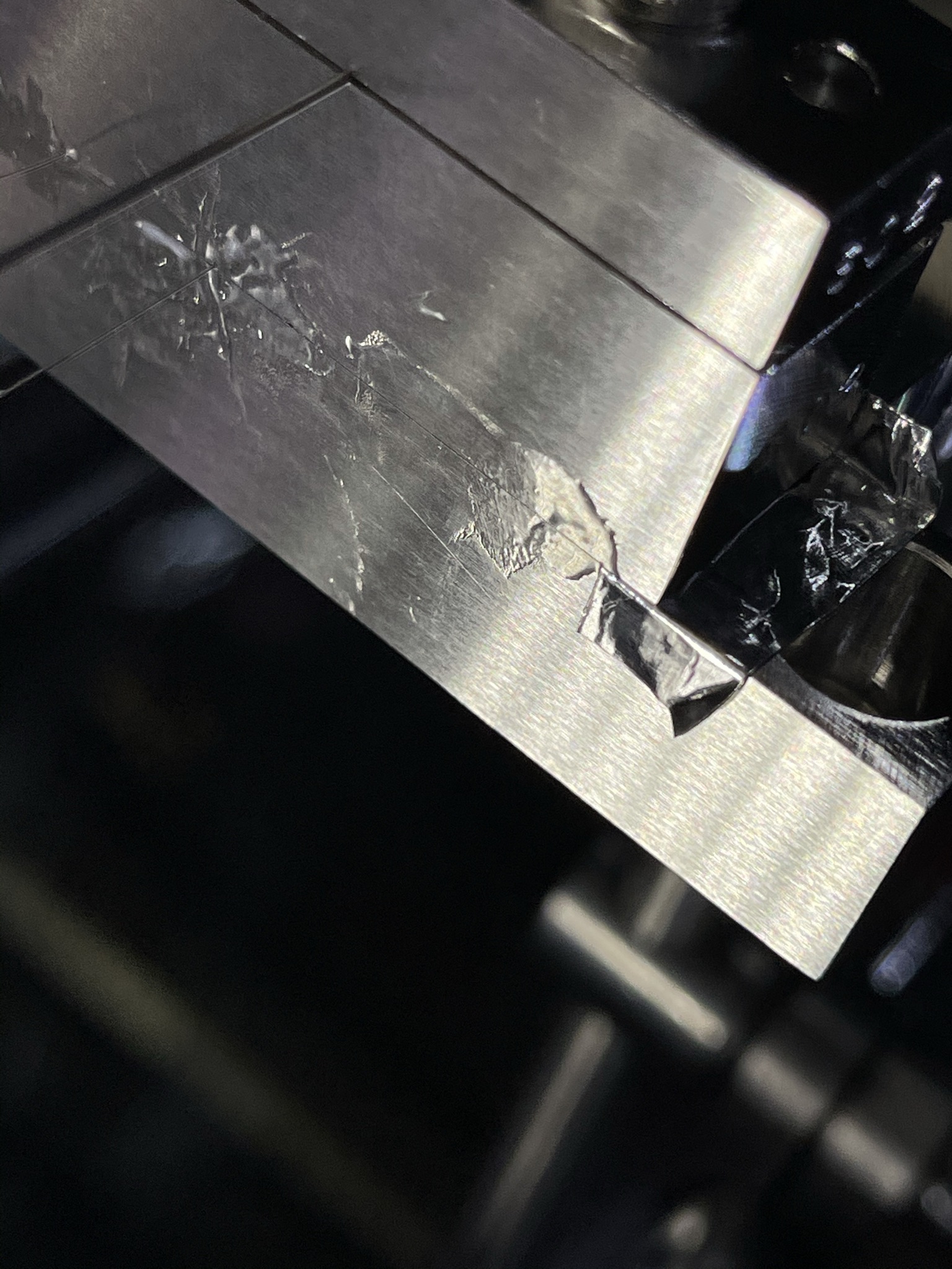
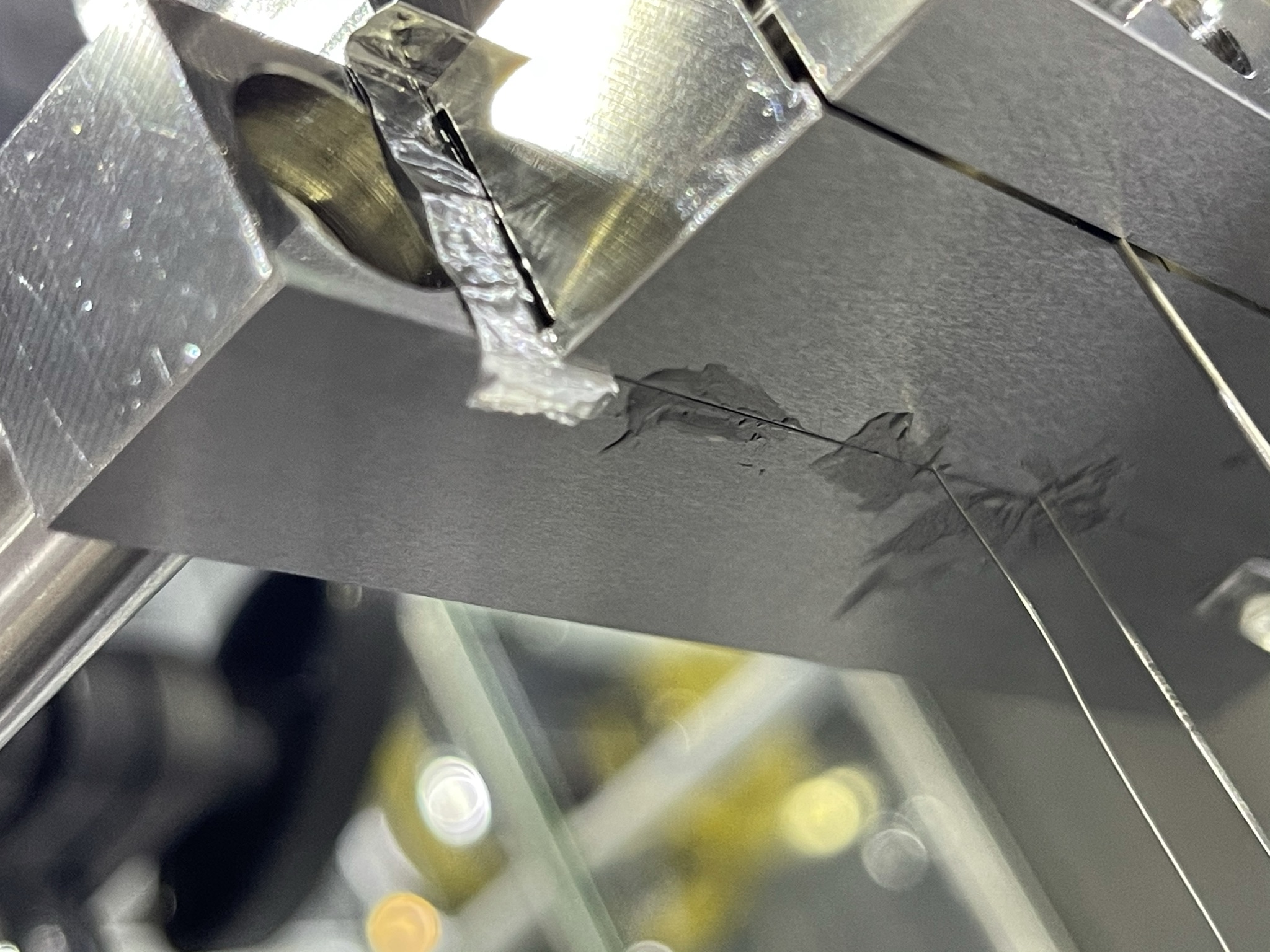
  • We removed the locating outer clamp. We saw it was scared, but the scars seem superficial. See this picture.
  • We after putting the spacers in place we tightened the screws of the inner clamps with "just a push".
  • We put the outer clamp back and tightened the screws witn a 2 Nm torque.
  • We measured the gap in the inner clamps to be between 90 um and 100 um.

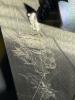
Then we applied the glue EP30. The tools we used to apply and wipe the glue are

We tried two strategies:

  • We applied the glue away from the wire and then to pushed it towards the wire with a teflon needle. At the end we wiped the excess with the spoon.
  • We applied the glue directly where the wire is, then wiped the excess with the rubber spoon.

We had the impression that not much glue went into the gap if any at all. In the best case just a small amount went in, which would not be enough to hold the wires in place. Tomorrow we will disassemble the clamps to check how much it went inside.  

Additional notes:

  • Just as a remainder, the should not be a blob of adhesive around the wires at the bottom face of the clamps.
  • Access to the bottom face of the clamps is difficult even in this experiment in which the clamps were set up out of the chamber.
Images attached to this comment
fabian.arellano - 12:09 Friday 26 March 2021 (16338) Print this report

With Hirata-san.

See pictures in album PR3 Remedying Work.

We cut the wires and disassembled the clamps to check how much adhesive went into the gap and onto the wire.

  • We confirmed the adhesive cured by examining the remaining portion.
  • The clamps were easy to separate despite the adhesive. See this video.
  • The adhesive did go into the grooves and around the wires. See this picture, for example.
    • Deposited adhesive can be seen clearly in the right wire. See this picture.
    • The left wire did not seem to have kept any adhesive on but its groove did. See this picture again.
    • The flat component of the clamp has marks where the wires were. The marks look like adhesive and not like scars. See this picture. We have to scratch to make sure they are not scars.
  • For the right wire we deposited a blob of glue around the wire at bottom face of the clamp and then smeared it and cleaned the excess with the rubber spatula.
  • For the left wire we deposited glue far away from the wire and then pushed it towards the wire with a soft tool.
  • It seems the method applied to the right wire got more adhesive int the groove.
  • Adhesive also went into the gap at the left side of the clamps. See this picture. As a test, here we applied the glue with the tip of a teflon needle and smeared it with the rubber spatula.
  • No blob of glue was created around any of the wire at the clamping points.

The test was successful in the sense that the adhesive went into the gap and the grooves around the wires. However, I wonder if this tiny amount of glue would keep the wires in place.

As information byproduct we learned that the scars in the outer locating clamp are rather superficial. We have the impression we can reuse them. The ones we tested were removed once and put back again. In both cases the screws were tightened with a torque of 2 Nm. See this picture. The tungsten wire was not damaged. See this picture.

Search Help
×

Warning

×