Miyo, K. Tanaka, Akutsu Partly cont'd from 16242
Abstract
- Replaced MCe oplev TX holder, and adjust the oplev beam to MCe so that the beam hits at around the center of MCe AR.
- Measured power budget of the oplev beams.
Power budget
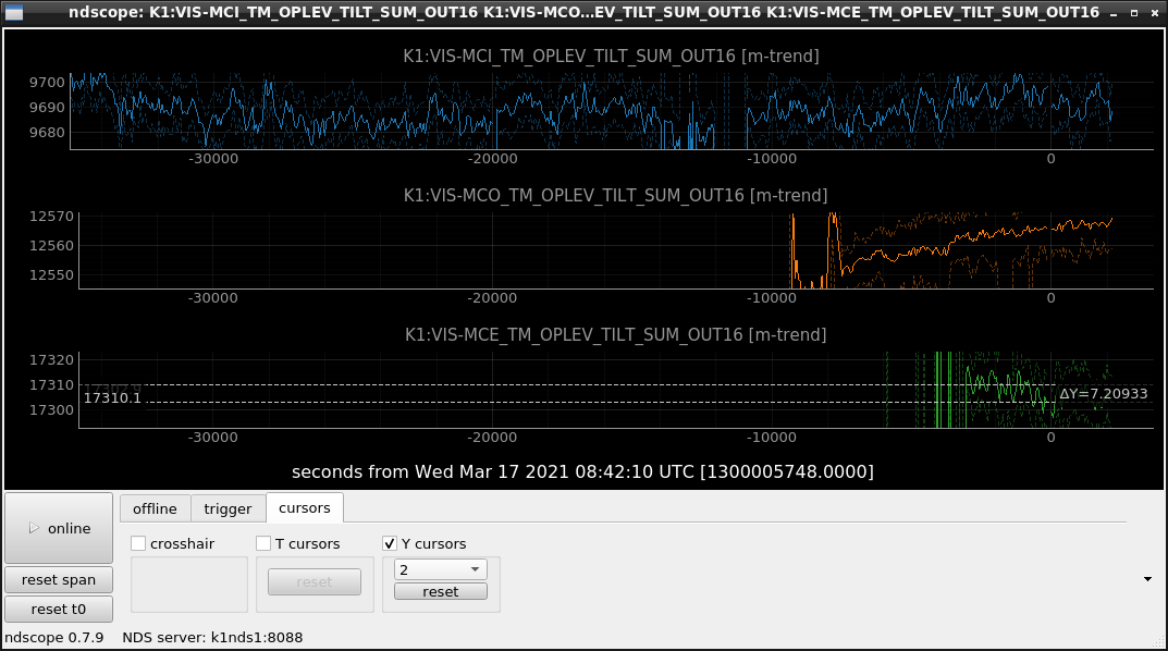
At MCi, MCo, and MCe, we measured the oplev beam power budget. The power was measured just after TX and in front of RX (i.e. QPD). In the following table, the correspoinding signals K1:VIS-MC{I,O,E}_TM_OPLEV_TILT_SUM_OUT16 are also shown, for comparison.
| Mirror | Power at TX (uW) | Power at RX (uW) | Counts (By eyeballs with Fig. 2) |
| MCi | 428.0 | 228.6 | 9692 |
| MCo | 627.8 | 318.6 | 12562 |
| MCe | 537.8 | 437.4 | 17310 |
So we could know 1. the conversion coefficients between the SUM counts and the power, and 2. reflectivity of each mirror with this setup.
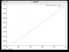
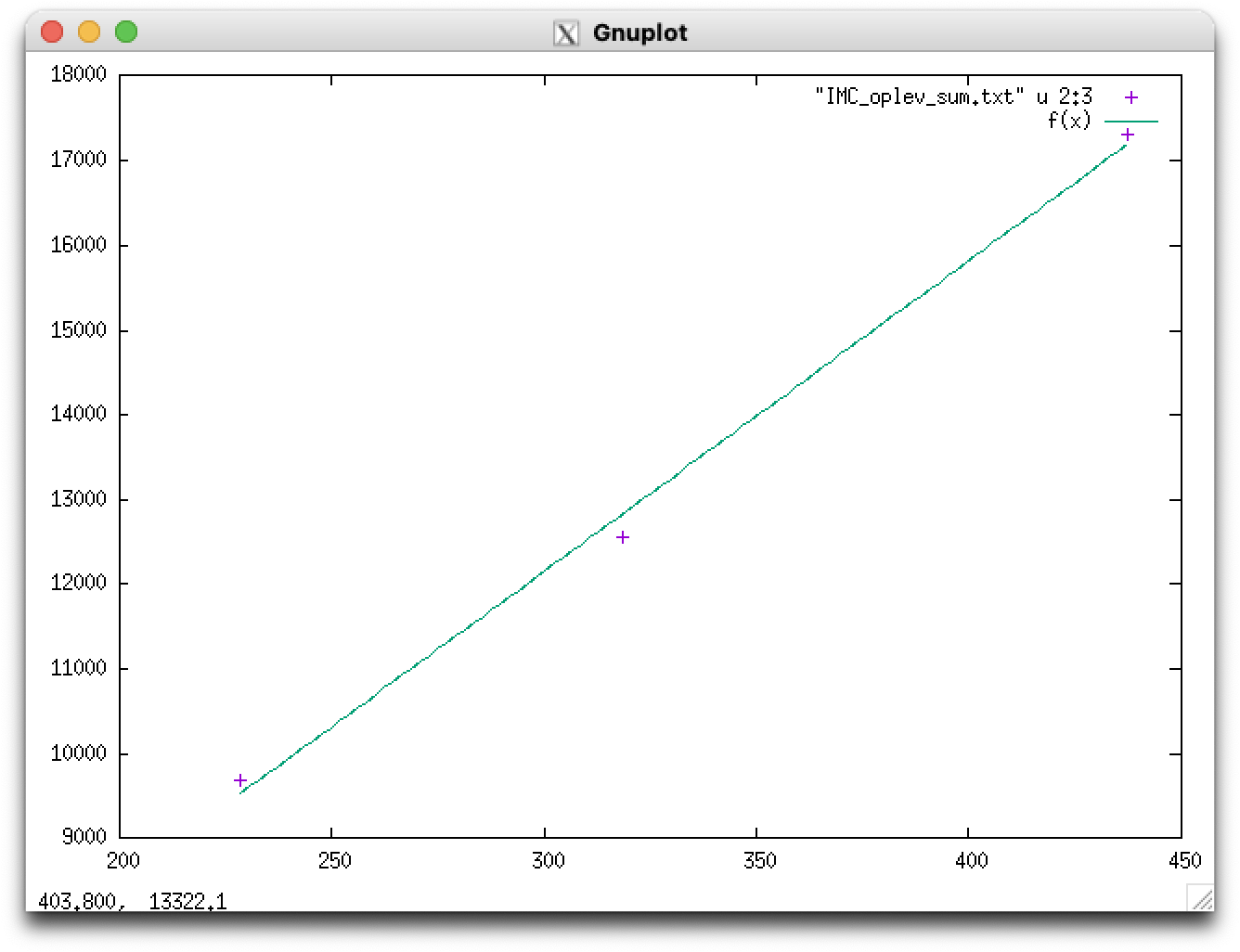
For the conversion coefficients, we expected that the plot of power at RX VS counts could be on a oblique line going through zero, but actually it turns out it is not ture. At this time we are not sure the reason. The fitting parameters of f(x) = ax+b are, a = 36.6657+/- 2.273 (counts/uW), b= 1154.32+/-770.9 counts (see Fig. 1); as I said, we are happy if b was zero. Before the measurement, we did zero the output, but this is the resutl. We will investigate more. And the method will be sophisticated more.
For the power reflectivity,
- MCi: 228.6/428.0 = 0.5341
- MCo: sqrt(318.6/627.8) = 0.7124 (MCo oplev is folded one, so the oplev beam was reflected twice at the AR of MCo)
- MCe: 437.4/537.8 = 0.8133
Note that the angle of incident for each mirror is different (MCi: 0deg, and I need to check the cad for the othe mirrors)
MCe oplev TX holder replacing
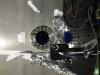
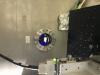
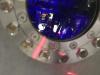
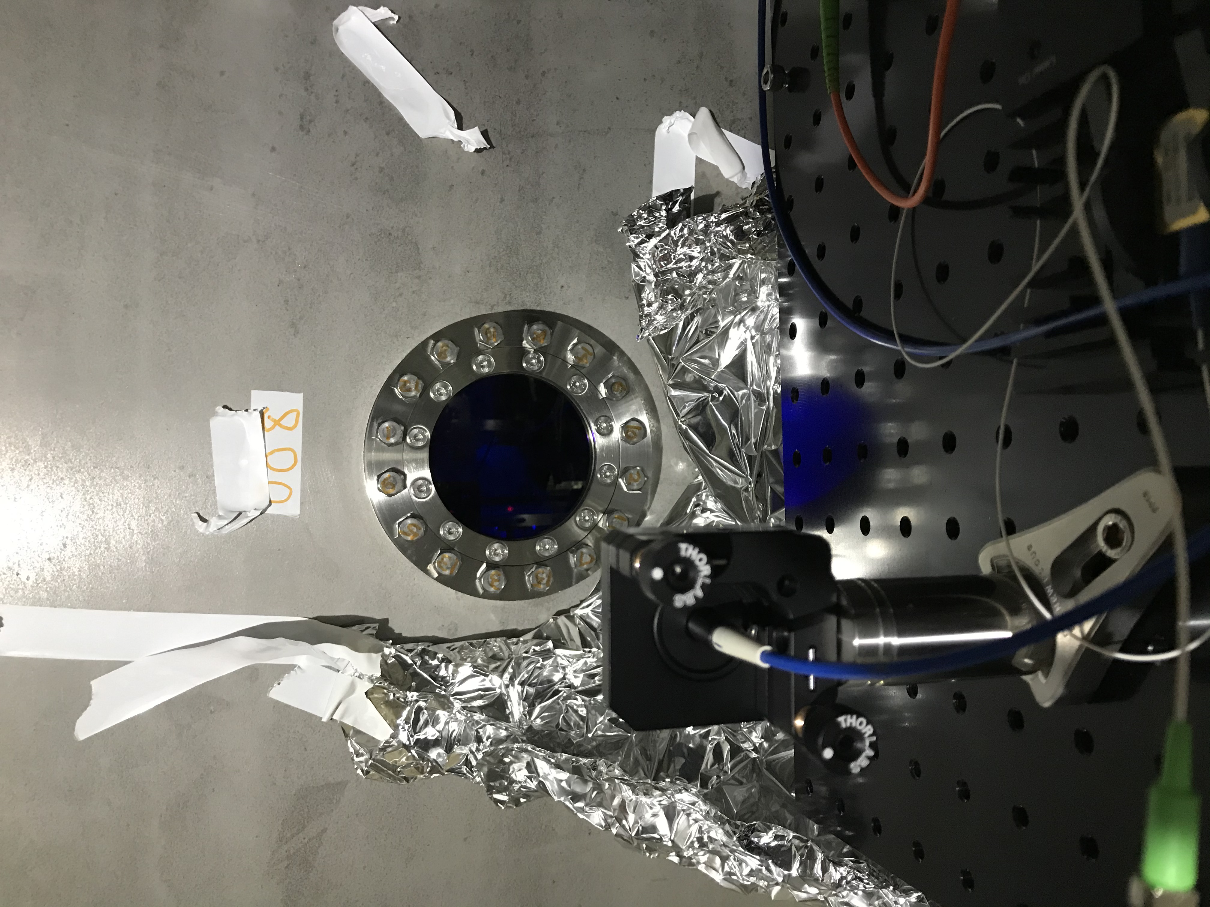
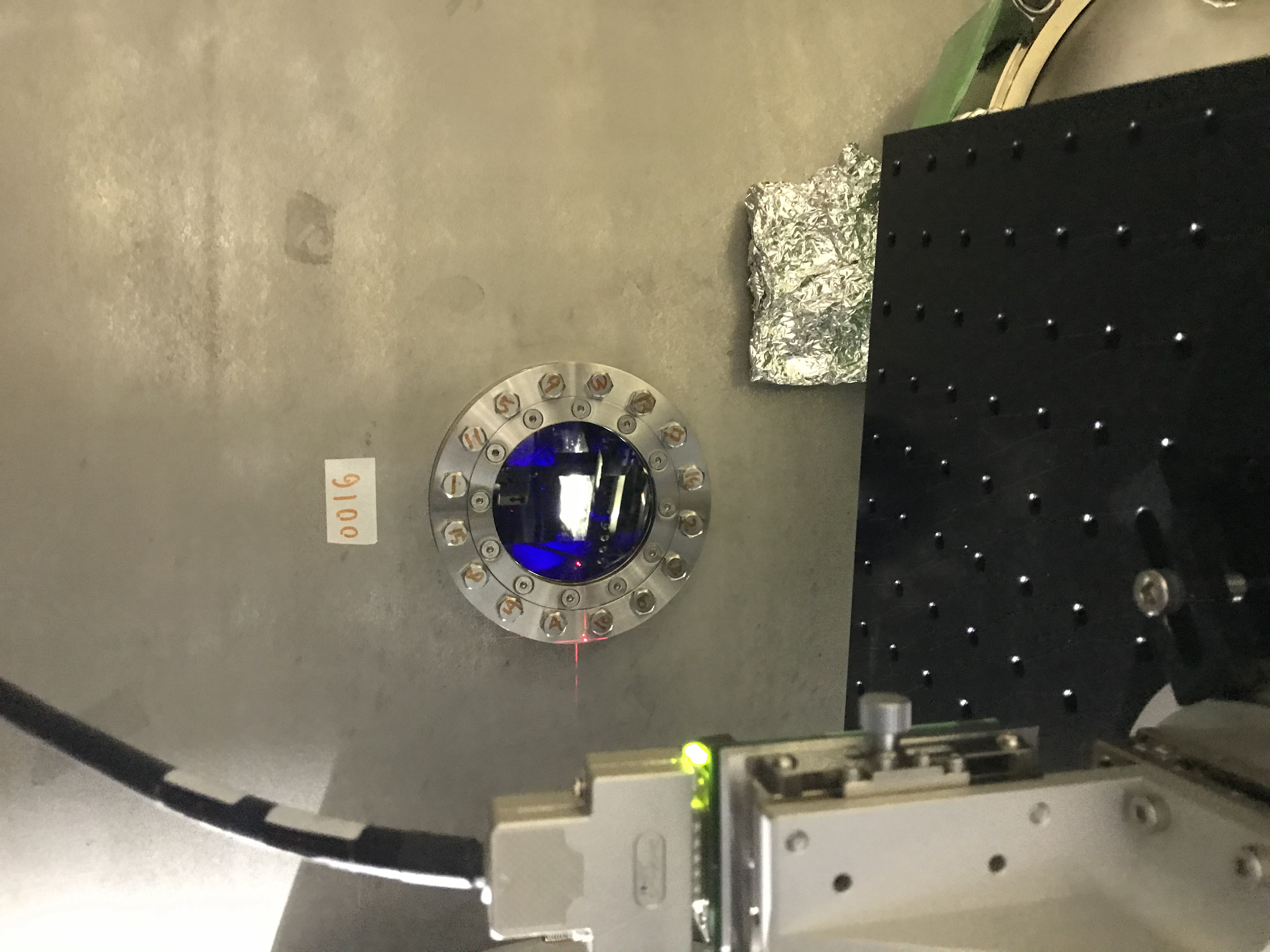
At MCe, before measuring the power budget, we replaced the oplev TX holder to the new one; this is the same activities like 16126 and 16242. Also, we had already known that the oplev beam was hitting at the wire break of the mirror so we adjusted this beam path by taking advantage of this chance. Now the oplev beam is not still displaced about 1 cm in. yaw from the center of the MCe AR, but we thought this is the best. The input beam goes through the edge of the input viewport window (Fig. 3), and the reflected beam goes through also the edge of the output viewport window (Figs. 4 and 5), and so this is the most balanced optical path so far as we found. The cross-like pattern found in Figs. 4 and 5 was made by the reflection of the QPD, as divided.
Notes
- Need to fix the light source driver.
- Need to dump the ghost beams like the cross pattern one described above.
By the way, for our works, I put aside the tilt sensor setup that have been at MCe.