Reports 1-1 of 1 Clear search Modify search
VIS (IY)
ryutaro.takahashi - 13:14 Friday 12 March 2021 (16249) Print this report
Connection of release sensors to DGS

[Takahashi, Sato, Hirata]

We connected the release sensors to DGS.

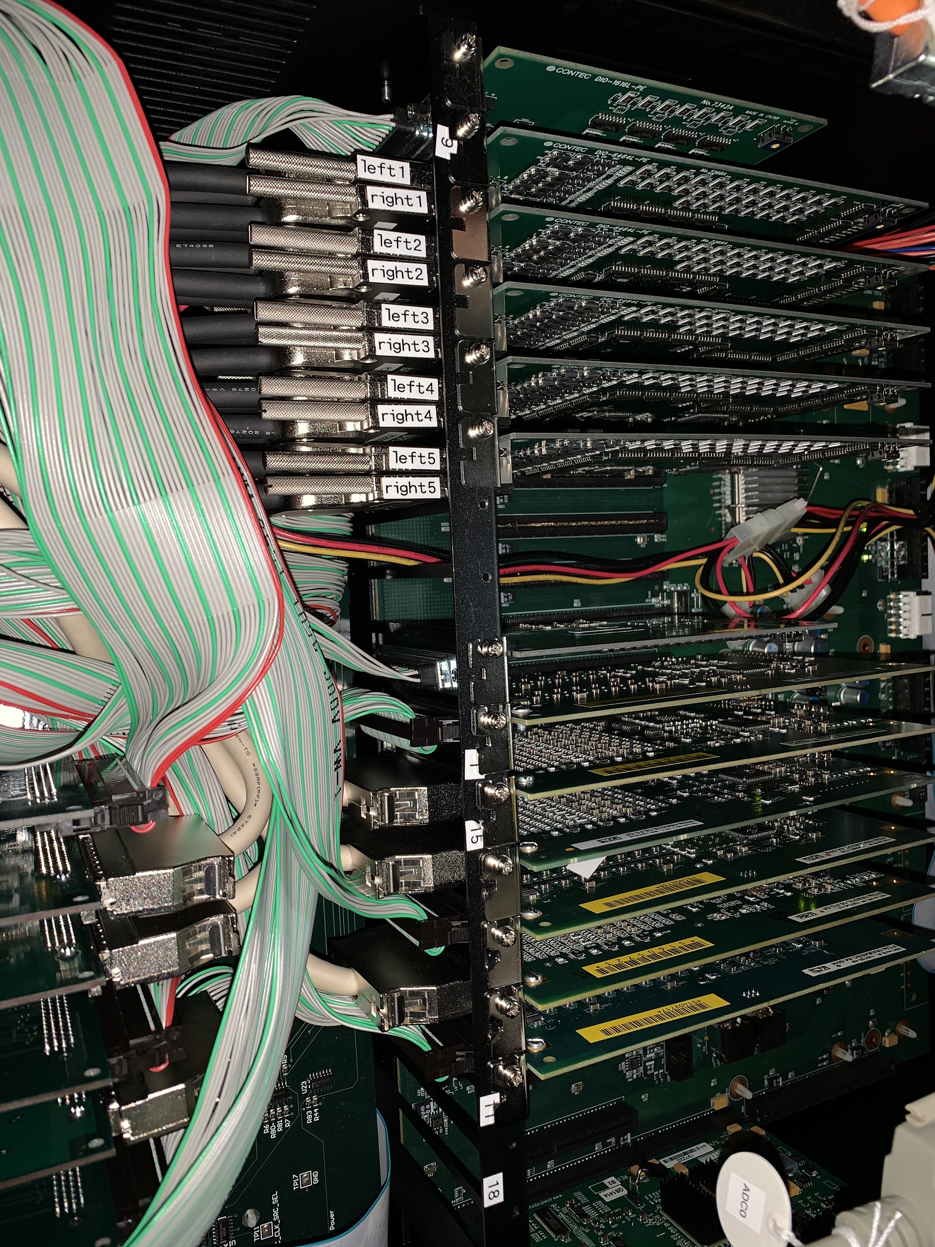
  1. Mounted the BIO shassis to the rack.
  2. Connected the outer cables to the feedthrough for the release sensors (F1, F2, F3, BF).
  3. Inserted the exchange cables between the shassis and the outer cables.
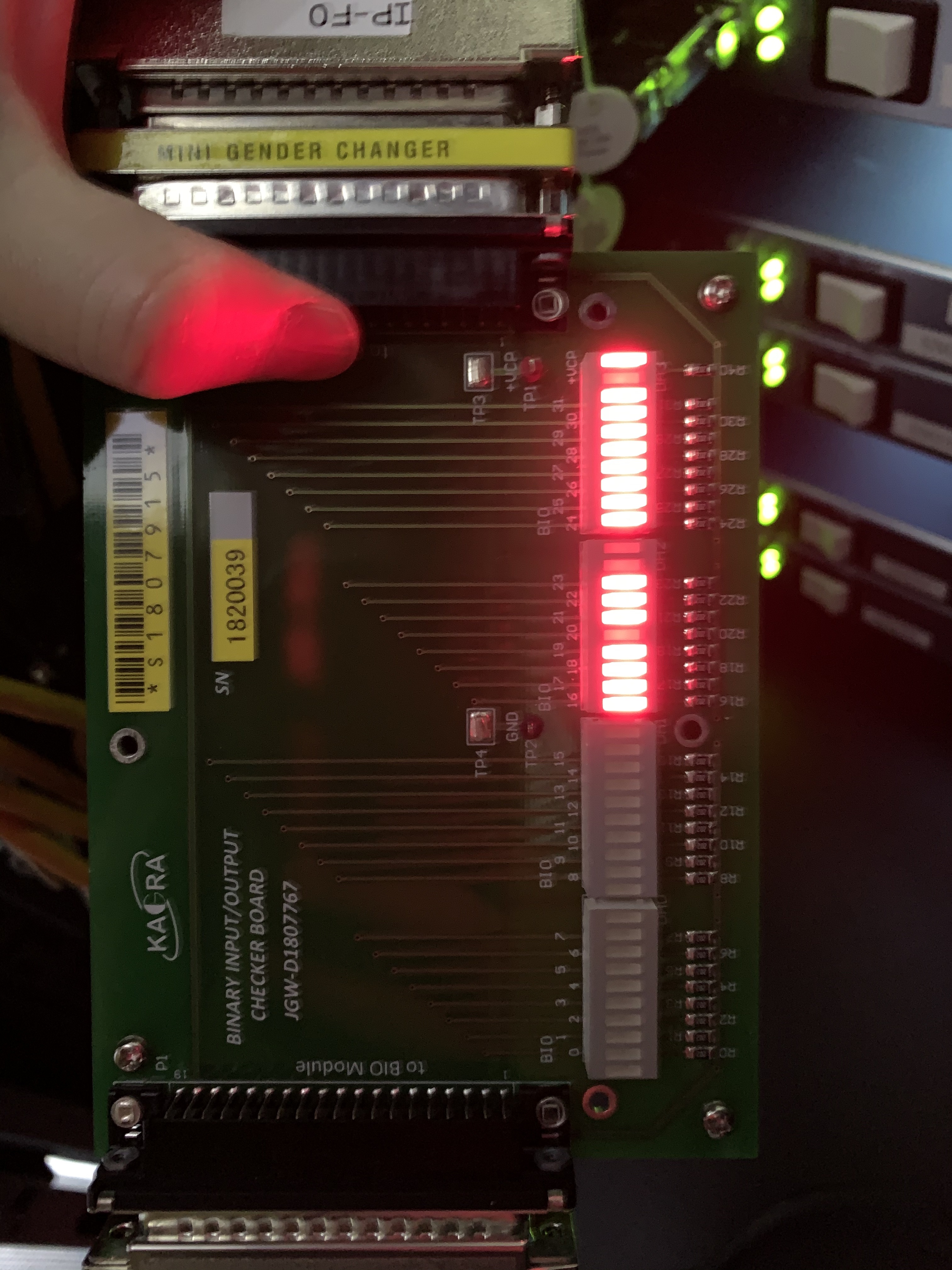
  4. Connected the D-sub 32pin cables from the 32-bit IO port on the shassis to the DGS (BIO4 right B) with the BIO checker. 
  5. Confirmed  the signal of F1 in the BIO checker.
Comments to this report:
naohisa.satou - 16:29 Friday 12 March 2021 (16251) Print this report

Attached is a memo about today's connection of the release sensor.

Non-image files attached to this comment
satoru.ikeda - 17:01 Tuesday 23 March 2021 (16307) Print this report

[Ikeda, Nakagaki-san]

BIO cable connection survey

Conclusion :
BIO4 RightB was confirmed to match the free number CBI(O)_H32_C4 in the model file.

Contents :
Investigated the BIO cable connection of IYV.
BIO is assigned from No.1.
I checked inside the I/O chassis and it was the same.

Below is the list of cable names.

White Cable Label Black Cable Label  
IP-F0 B-OUT CN A BIO1 Left A  
IP-F0 B-IN CN A BIO1 Right A  
GAS B-OUT CN B BIO1 Left B  
GAS B-IN CN B BIO1 Right B  
MNH B-OUT MNH B-OUT BIO2 Left A  
MNH B-IN MNH B-IN BIO2 Right A  
MN IMV B-OUT, MN IMV B-OUT BIO2 Left B  
MN IMV B-IN MN IMV B-IN BIO2 Right B  
IMH B-OUT IMH B-Out BIO3 Left A  
IMH B-IN CN A BIO3 Right A  
IM Dump B-OUT CN B BIO3 Left B  
IM Dump B-IN CN B BIO3 Right B  
TM B-OUT CN A BIO4 Left A  
TM B-IN TM B-IN BIO4 Right A  
Blank B-OUT Blank B-OUT BIO4 Left B not connected
Blank B-IN Blank B-IN BIO4 Right B not connected
BFV B-OUT CN A BIO5 Left A  
BFV B-IN, BFV B-IN BIO5 Right A  
BFH B-OUT BFH B-OUT BIO5 Left B  
BFH B-IN BFH B-IN BIO5 Right B  


Check procedure
 K1:VIS-ITMY_BIO_CDCTRL_NOTUSE_WD_RESET OFF->ON
 Verify that K1:VIS-ITMY_BIO_CDCTRL_NOTUSE_DIO_OUT is set to 0 to 65536.

 On the model, In17 (starting at 1) = Binary IO Checker bord, I confirmed that No.16 (starting at 0) is ON (LED lights up).
 I confirmed that the LED turns off when I set it to OFF.

Images attached to this comment
Non-image files attached to this comment
satoru.ikeda - 18:14 Wednesday 24 March 2021 (16319) Print this report

Added an EPICS channel to check the status of the release sensor.

Channel Name :
K1:VIS-{ITMX,ITMY,ETMX,ETMY}_{F1,F2,F3,BF}_RELEASE_SENSOR_{1,2,3}_INMON

Updated model file:
Updated both Tower and Payload:
ETMX,ETMY,ITMX,ITMY
SRM, SR2, SR3, PRM, PR2: TypeB/Bp updated because common files were modified.
(BS and PR3 have not been updated)
Update time GPSTime:1300610931
Git Commit ID:cef968a3ee8dd555f0e7d43423e000085ac751b8

MEDM:
 sitemap-VIS-VIS OVERVIEW-[ETMX,ETMY,ITMX,ITMY]Button-GAS
 Add ReleaseSensor status to VIS_GAS_OVERVIEW.adl


Non-image files attached to this comment
Search Help
×

Warning

×