On Mar. 9. Contiued from the previsous post. YamaT, Akutsu with help by Shimode
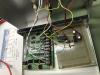
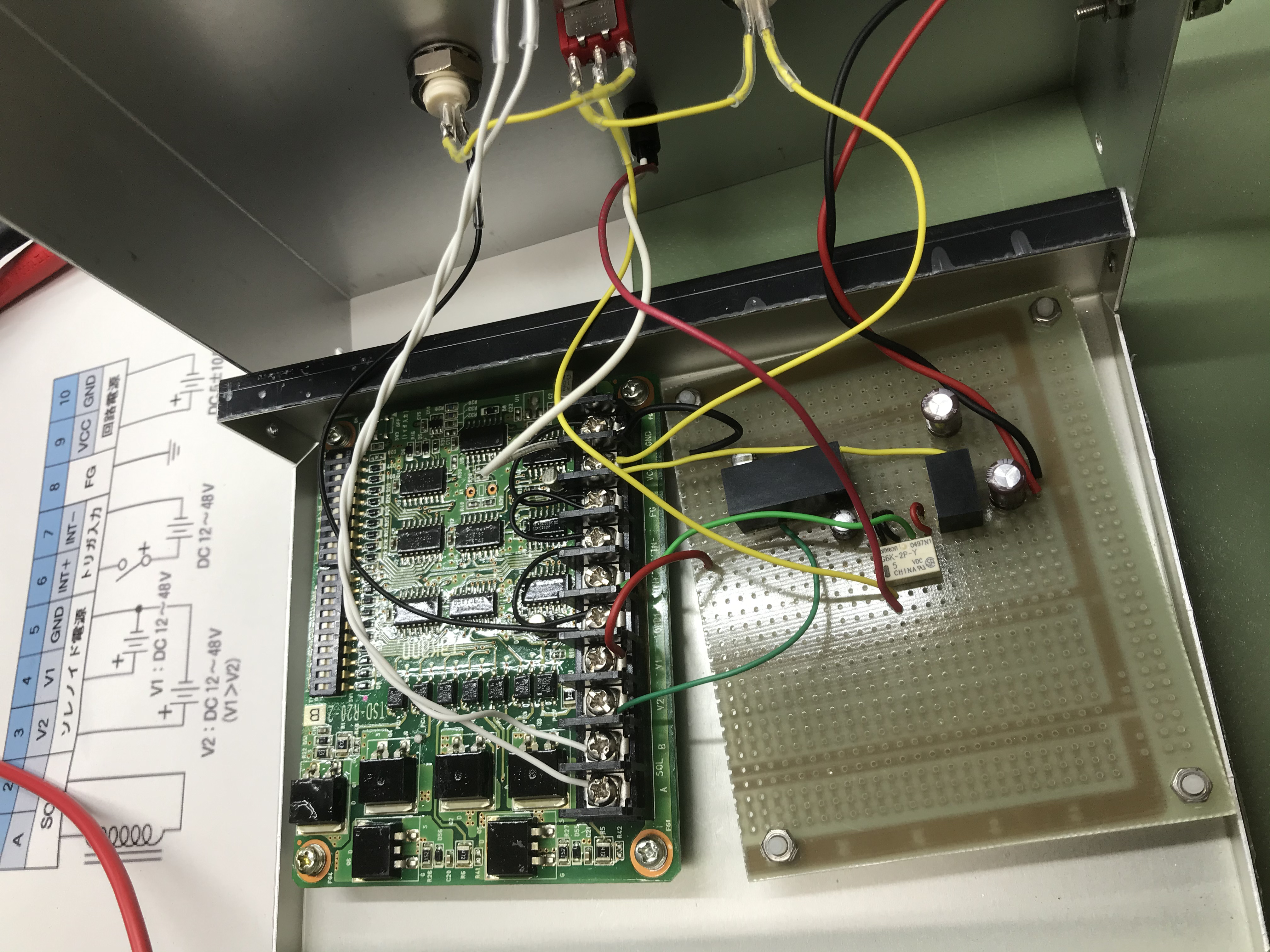
Inspected in the shutter driver circuit (Fig.1) at the Mozumi office, and our conclusion is that this circuit has not been broken, maybe; it depends on the definition of "ok" state especially in this case, as this is critically related to safety management topology, rather.
- We need an acceptance check list whether the output of the circuit would be as intended (designed) or not; note that this intension must be certified by Safety and AEL, I guess. For example, when the driver circuit is connected to 24VDC power supply, the pair of the output pins to be connected to the solenoid coil of the shutter shows minus 8V, while it is reversed (i.e. +8V) when we provide 5VDC (with 800 mA-limit-set) to the 5V-relay that switches 24VDC to the main circuit (in). I am not 100%-ly sure if this is the expected behavior, although I know the shutter opens in the end with this driver circuit; what should have been the behavior of this driver circuit when it is in the idle state?
- The circuit board for the power supply management seems handmaded by amatures. Plus, some soldering seems done by amatures. Plus, the circuit boards shown in Fig. 1 are not fixed to the circuit box. These issues should be fixed.Todaay Shimode-san repaired tentatively some of the soldering, but I believe we need the overall should be revised under the manaagement of Safety and AEL to be a proper part of critical safety path.
- By the way, I have heard this driver circuit was modefied to deal with the power consumption issue, but I am not sure well about it. Does anyone lead me to a proper report on it??