Yano, Akutsu
Abstract
Move the WAB into the saving mode at IYC with the new WAB traverser, but still small remaining works.
Detail
- The WAB's base plate in IYC is fixed on the top of the breadboard with the narrow-head M6 screws as designed (not clamps).
- Two thermometers each has been fixed to the WAB and the WAB suspension structure, respectively, and they are not mechanically interfere against the triangular-shaped protecter to fix the suspended mass, so we did not detach them.
- The 6N Al heat links should be detached. They are packed on a tray that has been also holding unused 6N Al heat links and stored in the shelf at the side of IMC vacuum tube.
- We were able to install the revised new WAB traverser under the WAB, and make it in the saving mode. But this had been already succeeded; the real charanges started from here.
- There are two real issues; whether (1) the jig could be picked out under the WAB at the nominal position, and (2) we can re-install the jig under the WAB in the saving mode. So far, (1) was succeeded, but maybe more difficult and risky than the way to use the old traverser (suspending type). For (2), hmmm, we tried slightly, and maybe it seems in theory it is probable by well-understad engineer. For example, it is too clumsy for me to do it without Yano-san's help.
- Anyway, after moving the WAB, we put the protect rings as usual to protect the front edge of the WAB, and covered whole the WAB strcuture with aluminum.
There are some remaining tasks so we continue the work there tomorrow.
- Would like to apply a birndy connector structure (PEEK) to the pins for the thermometers, which are now naked.
- Will pack the WAB traverser parts and so on to clean up there.
- Yano-san will prepare a user document of the new revised WAB traverser.
Figures
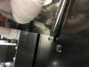
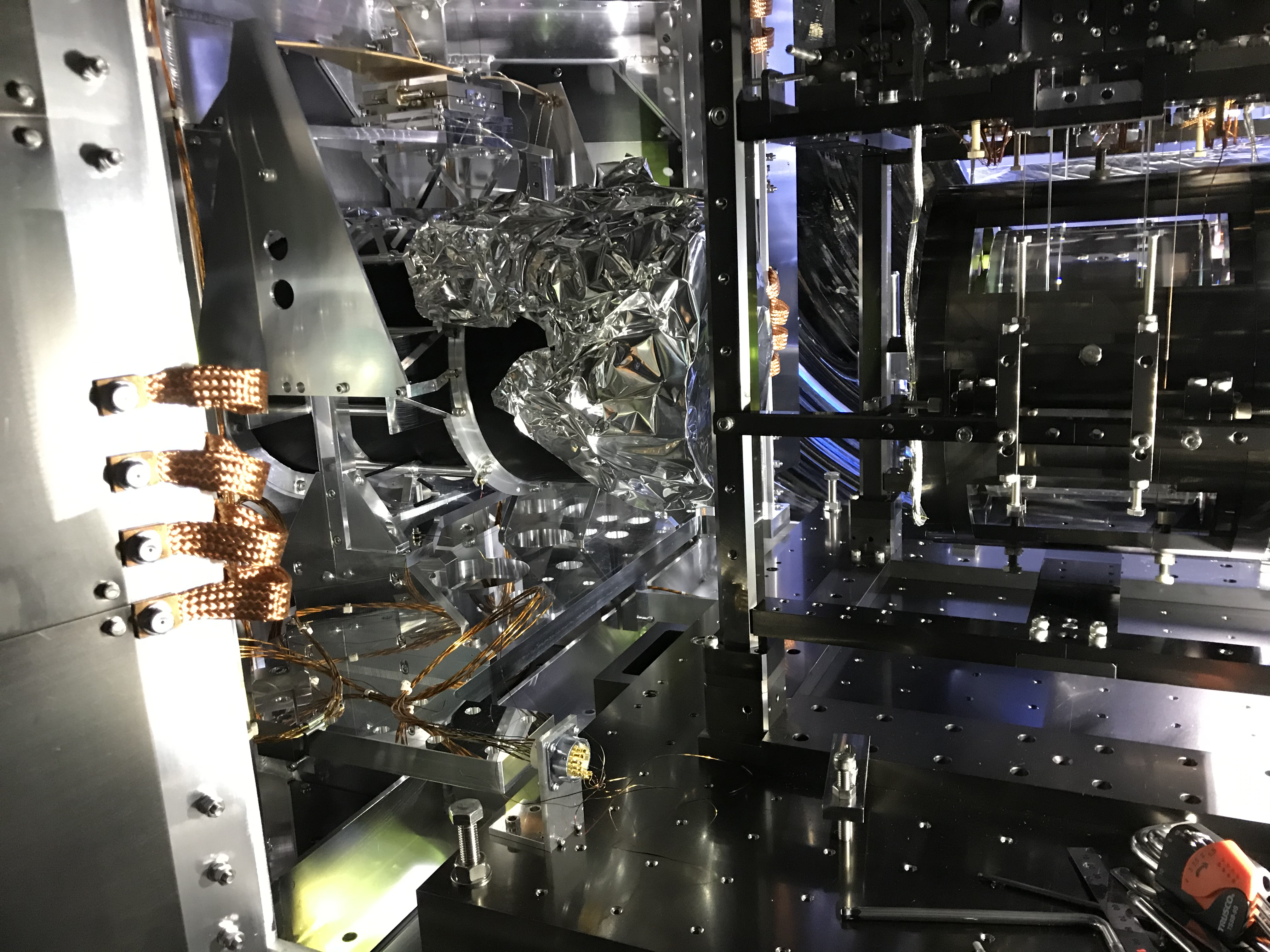
- Fig. 1: the revised new WAB traverser lifted up the WAB whole structure about 3 mm from the top of the breadboard in the cryostat.
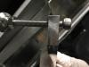
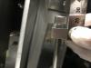
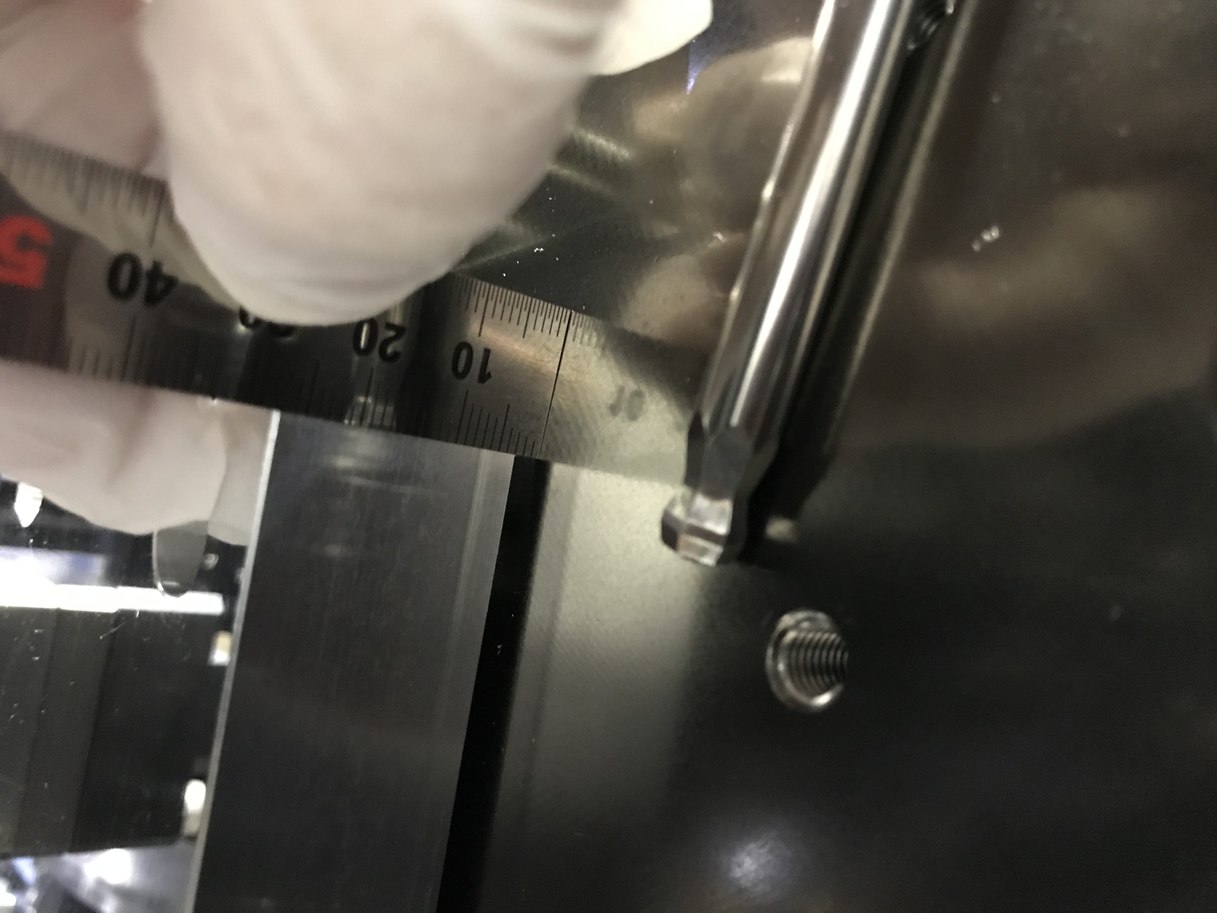
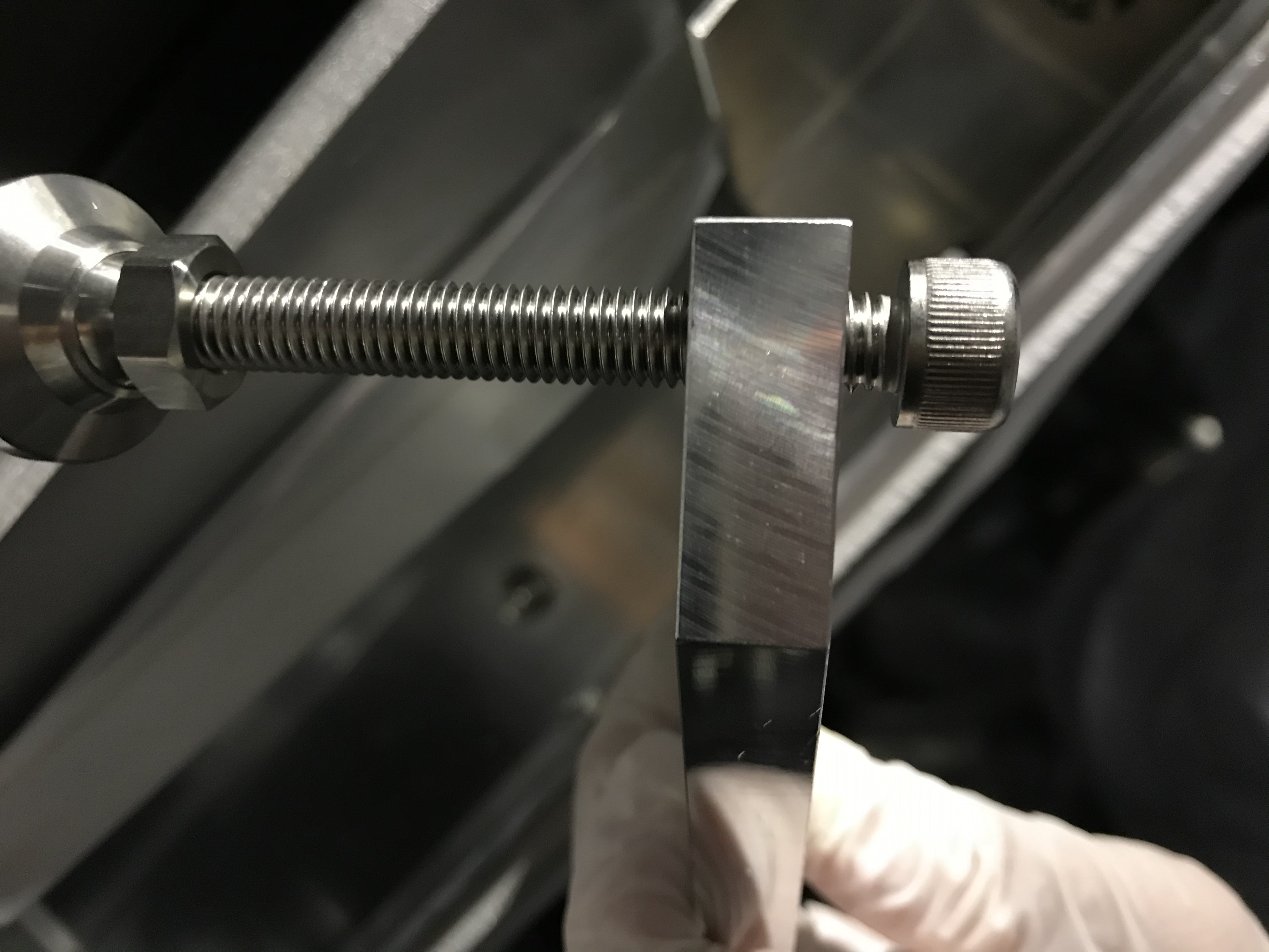
- Figs. 2 and 3: to record the suitable hight of the bolt leg that was used (and now is detached) at the back of the WAB traveser ("back" is the arm side/ "front" would be the mirror side).
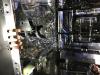
- Fig. 4: the WAB in saving mode.