N. Sato, K. Tanaka, Nakano, Akutsu
Abstract
To put some stray-light mitigation staffs (black shields and beam dumps) in the MCF and MCE chambers, we started with inspecting the suspension structures for MCi, MCo, and MCe. We found several things to do before starting the installation of the staffs. For MCi, we relocated the connector plate and attached four adapters to the suspension pillars. For MCo, we could not do anything. For MCe, we relocated the connector plate. See here as well.
Main
To mitigate the stray-light noise, we need to put some shields and dumps in the MCF and MCE chambers. Today we tried to attach the shields onto the mirror suspension structures (for MCi, MCo, and MCe). The similiar shields have been already installed at OMMT1, 2, OSTM, IMMT1, 2. How to attach the shields is described in the Sato-san's procedure document. According to this, we need to start with relocating the connector plates of the suspensions.
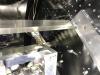
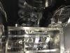
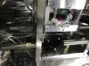
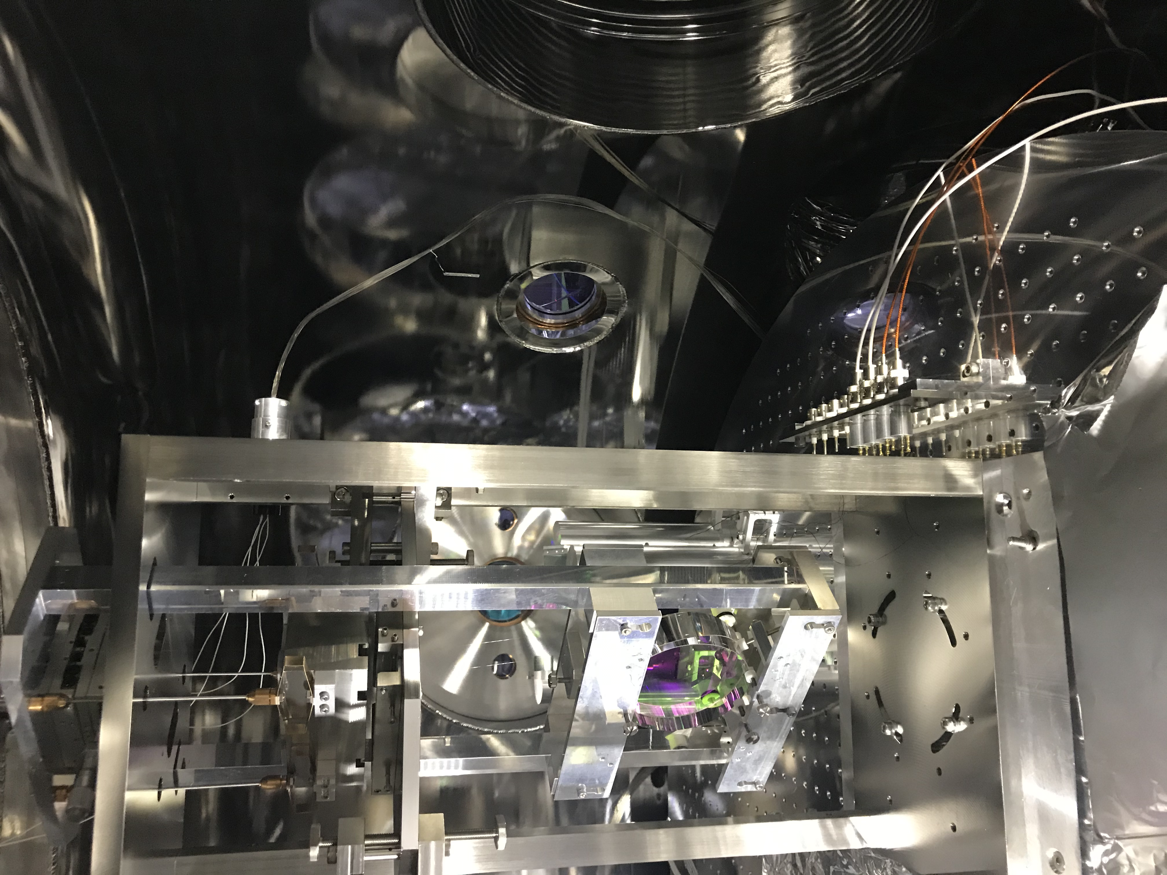
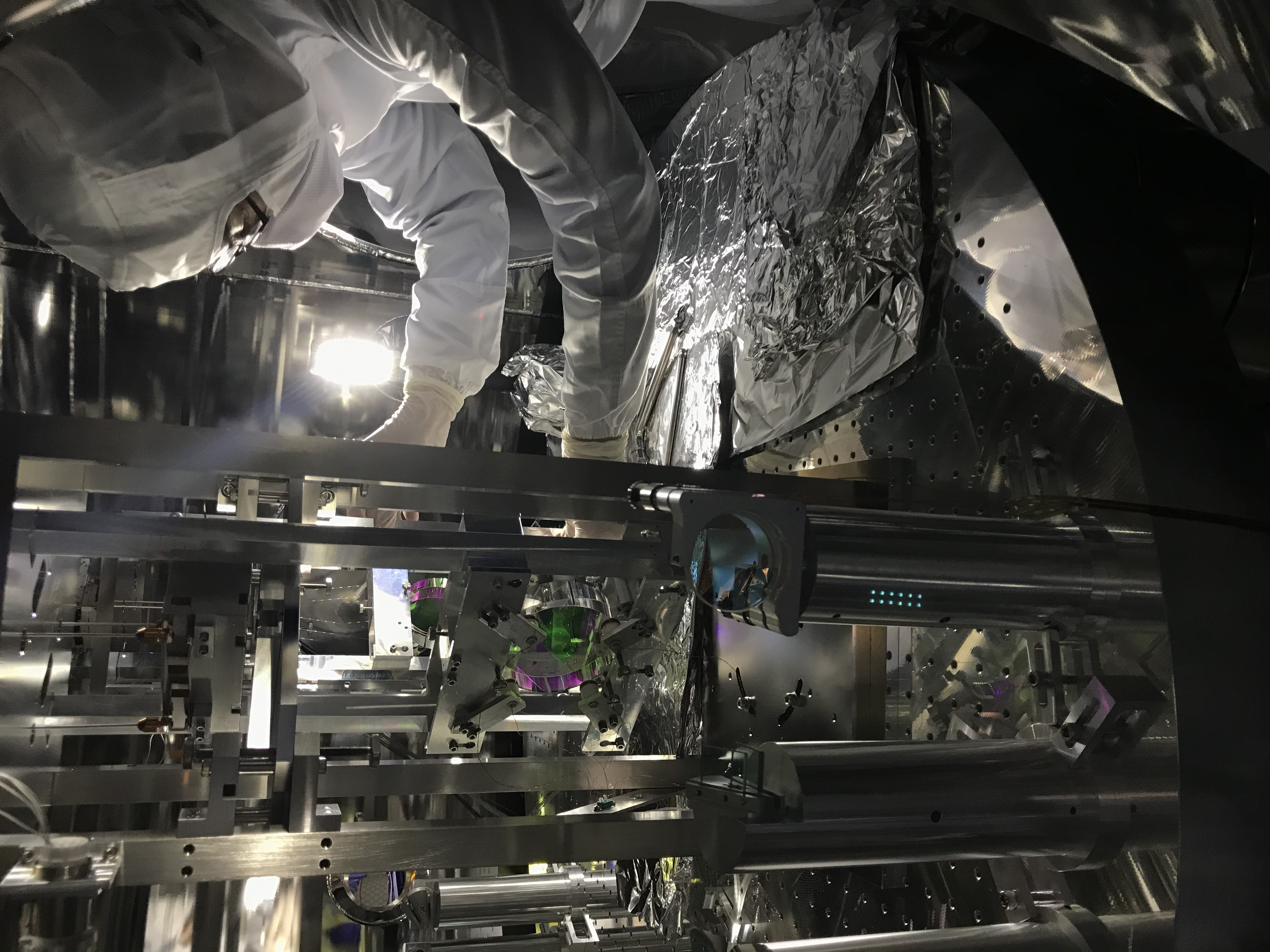
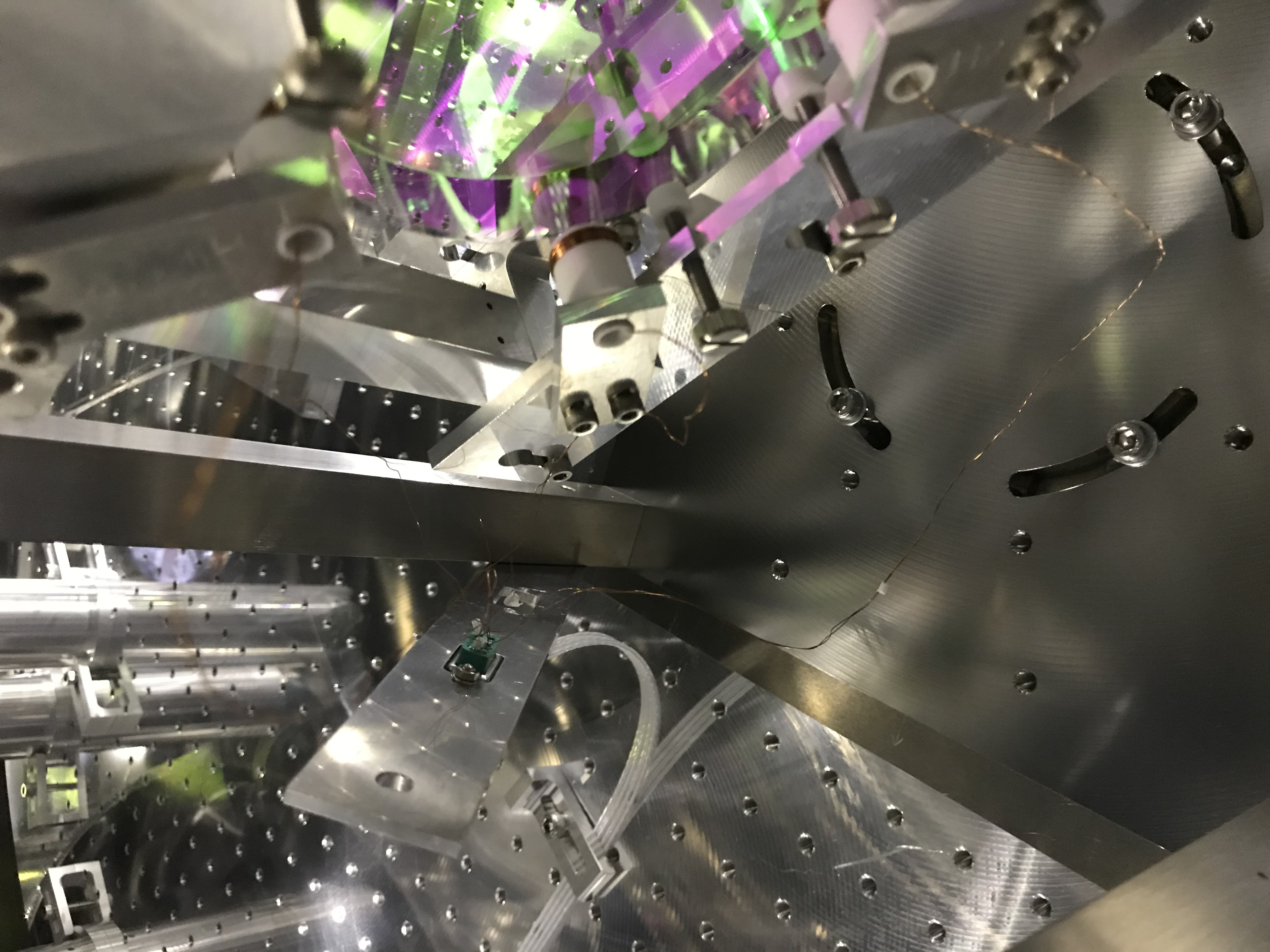
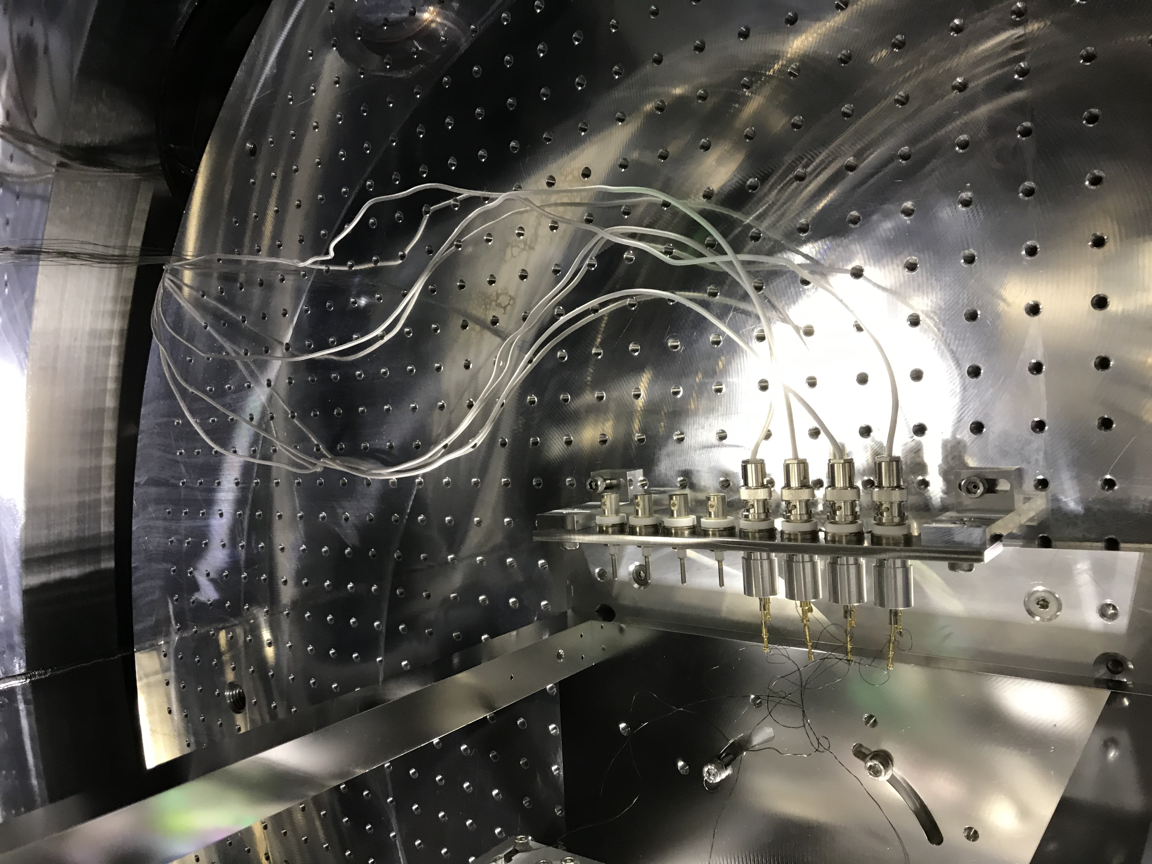
After the treatment in 15914, we started with inspecting the MCi suspension. It was hard to see the coil wires from the flange side, so we put some aluminum foils on the top surface of the optical table in the MCF chamber so that one could step in the chamber. By stepping into the chamber, I could see the coil wire was maybe sufficient length to relocate the connector plate. So, we relocated it --- we detached from the pillar of the suspension, put two legs to the plate, and fixed it on the top surface of the optical table (Before: Fig 1 (the plate was tilted and fixed with only one screw)-> After: Fig 2). Then, we attached four adaptors onto the suspension pillars as planned (Fig. 3). The adaptors are required to attach the black shields, as the suspension pillars do not have suitable screw holes so far.
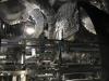
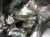
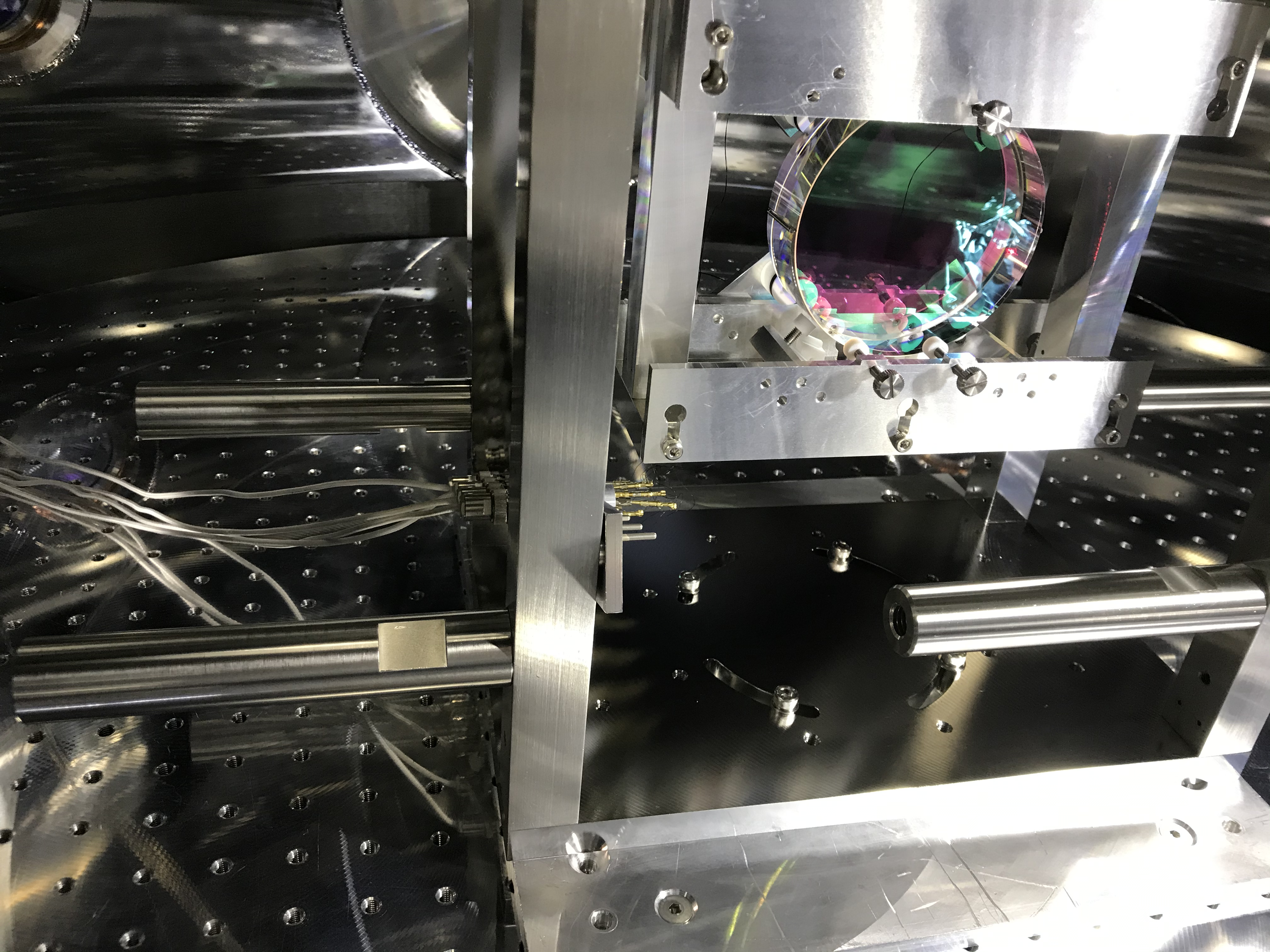
Next, we inspected the MCo suspension, and it turned out that it is almost impossible to relocate the connector plate, as the electric wires from the actuator coils were too short (Fig. 4). We need to ask VIS to repair this, if we will attach the black plates. So we gave up the work today, and closed every flange and moved to the MCE chamber.
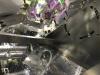
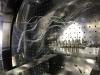
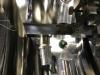
Then, at MCE, we also needed to do the treatment as reported in 15914. Then we detached four bars from the MCe suspension structure pillars. These bars (Mikosi bou; Fig. 5) are for handling the suspension structure (with the mirror?? I'm not sure.) but for some reason they have been left. By the way, in Fig 5, you can see one of the four bars are not symmetrically directed. This is due to that one of the four pillars had been assembled in the 180-deg wrong direction, and so Sato-san needed to design a dedicated adapter only for this pillar (see the above document). The bars are now put in a plastic box on the shelf in the side of the MCE clean booth. Then we put aluminum foils on the optical table so that we can step on, and relocate the connector plate in the +Y direction of the suspesnsion (Figs. 6 and 7). To do so, we once needed to disconnect cables, and re-connected them after relocating the connector plate.
Anyway, we need to call VIS people to modify and check some points before installing the shields.
- Coil wire fixing: I am worried about that the coil wires might be cross the light beams because the wires are not fixed to the suspension structure. This must be resolved.
- Short coil wires: as describe above. For MCo.
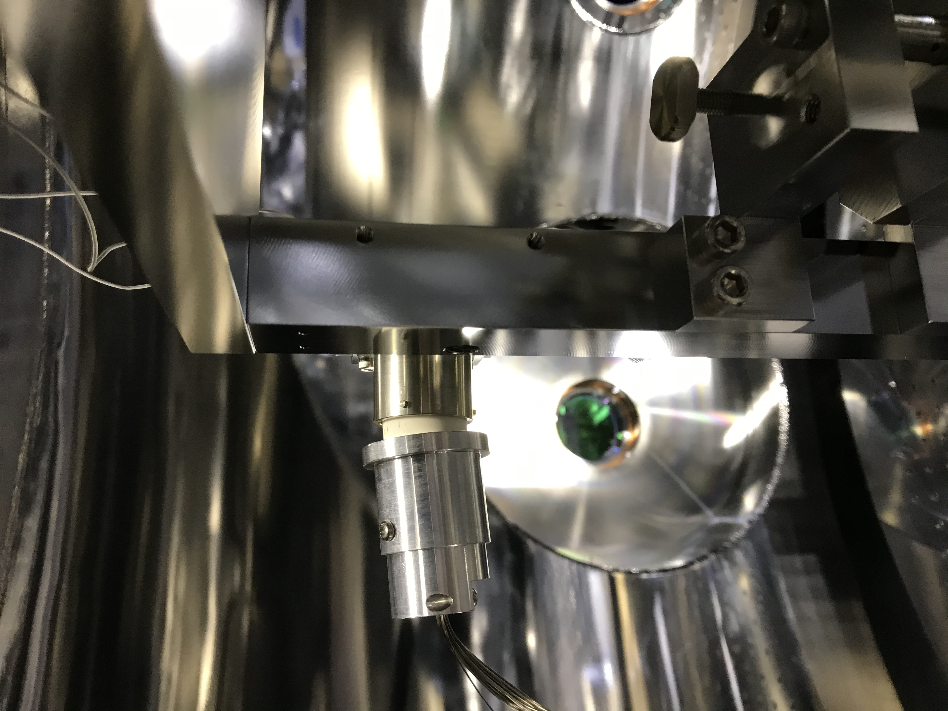
- Loose birndy connectors: It was obvious that the birndy connector was loose at MCe (Fig. 8). But the same would happen for MCi and MCo, so need to check or modify them