(Log on 22nd.)
I tested a new LVDT combiner circuit. The H1 coil (photo) for BF damper was used. The BF is fixed by the EQ stop. The primary coil is located at the right side limit.
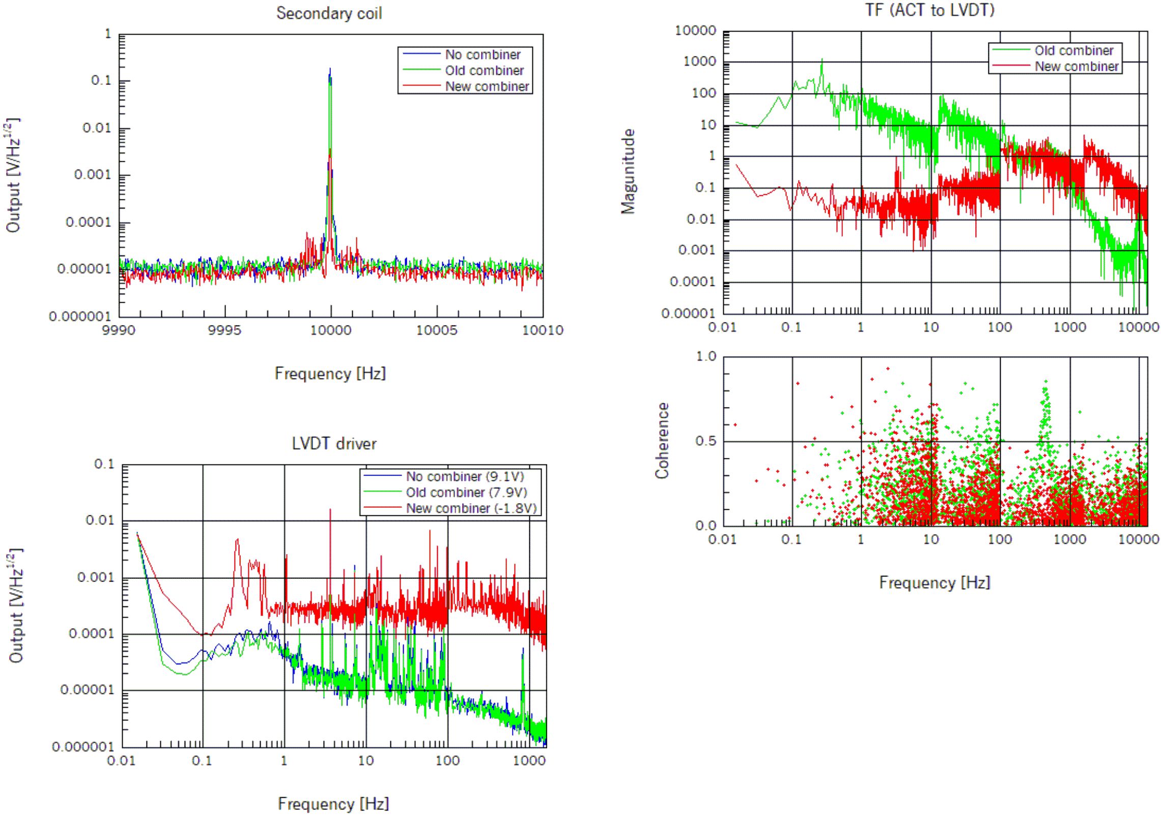
- Signals of the secondary coil induced by the primary coil at 10kHz: The signal through the old combiner was reduced by -4dB. The signal through the new combiner was reduced by -34dB!
- Noise spectrum of the LVDT driver output: Though DC output through the new combiner (demodulation phase was optimized) was smaller than DC output without combiner (about 1/5). the noise lebel was larger.
- Transfer functions from ACT input to LVDT driver output: Coherence was small. The signals from ACT input might be reduced by the band-pass filters in the new combiner.
