Adding ballast mass to the top of the BF sounds like a very easy task. However, the challenge is to add mass and, at the same time, keep the existing balance, in pitch and roll, of the BF. Becuase the IRM with the OSEMs hangs from the BF base with three thick (2 mm) maraging steel rods, any change in the orientation of the BF would affect the OSEM alignment. In the worse case the OSEM bodies would touch the OSEM flags.
On Tuesday afternoon we added ballast mass on opposite sides of the BF top:
-
We put 66 grams at each side.
-
At the -Y side we put mass in an unused space and the 66 grams includes the mass sof the screw.
-
At the +Y side we had to put the ballast mass on top of other masses and we had to change the existing screw by a longer one:
-
New ballast mass (66 g) + old screw M6 L35 mm (9 g ) = 75 g
-
New ballast mass (63 6) + new screw M6 L50 mm (12 g) = 75 g
-
We fastened the screw by hand because we required to test the result before commiting.
-
We released the BF, which had been locked to the side security structure.
-
Right after putting the masses we had to leave the site due to heavy snow outside.
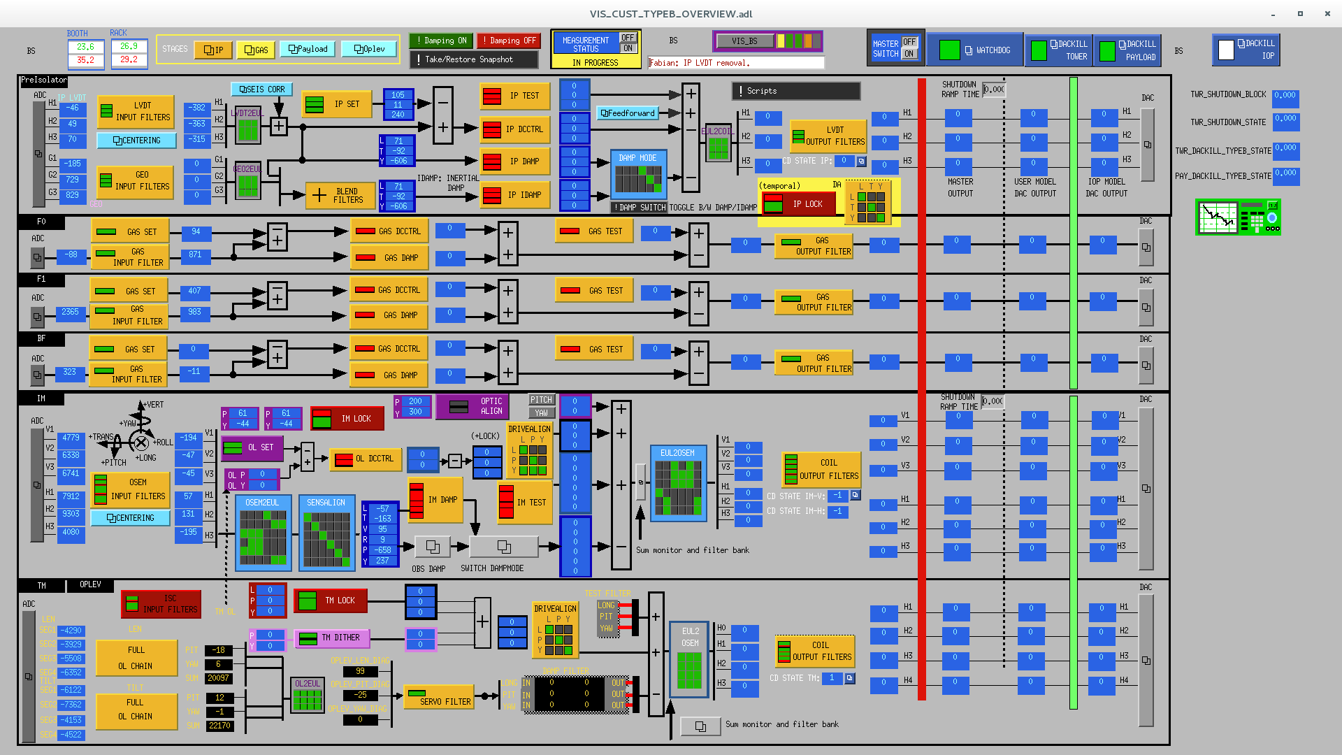
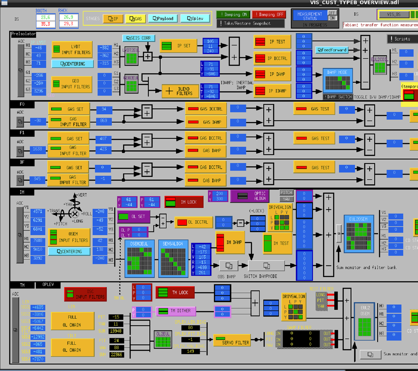
Today I measured transfer functions and also I compared the new position with the old one. The results are good:
-
The IM transfer functions show a heathly system. I didn't measured the one for IM-V because F0 is locked.
-
The addition of the ballast masses to the BF changed the orientation of the IRM slightly but this does not create any problems. The largest change was -42 µrad in IM-P. See the atteched picture.
-
The changes in the readout of the IM OSEMs are due to a change in the orientatio of the IRM, not of the IM, which remains in place.
-
The only chnage in the oplev QPD readout that is significant is in TILT QPD H, which indicates the optic moved in yaw. I'm not sure yet why this happened.
-
Current temperature: 23.6 degrees.
-
F1 keystone moved down by -560 µm to 423 µm. Because the goal is 212 µm, we will need to add more mass later once the temperature is suitable.
|
|
L |
T |
V |
R |
P |
Y |
LEN QPD V |
LEN QDP H |
TILT QPD V |
TILT QPD H |
BF |
F1 |
|
Difference |
15 µm |
-10 µm |
8 µm |
-22 µrad |
-41 µrad |
24 µrad |
3 ndu |
5 ndu |
12 ndu |
89 ndu |
-10 µm |
-560 µm |
-
The acronym ndu means normalized displacement unit [-100,100].
-
The DTT files with the transfer function measurements are in TypeBData/TF/Measurements/20201217/
As a conclusion we can say that it's not so difficult to add ballast mass on top of the BF without disturbing the alignment of the IRM. However, I should check whether there is an obvious reason for the yaw of the mirror to change.