Description
As pointed out in other entries, by mistake we used at each Type-B suspension a couple ferromagnetic connectors (photo1) near to the magnetic damper at the SF stage.
- In BS, SR2 and SR3 the connectors are monted onn the top of the SF underneath the magnets:photo2, photo3.
- In SRM the connectors not on the top, but a bit further down: photo4, photo5.
This entry reports the measurements of transfer functions in which the effect of the different positions of the connectors might be seen.
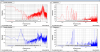
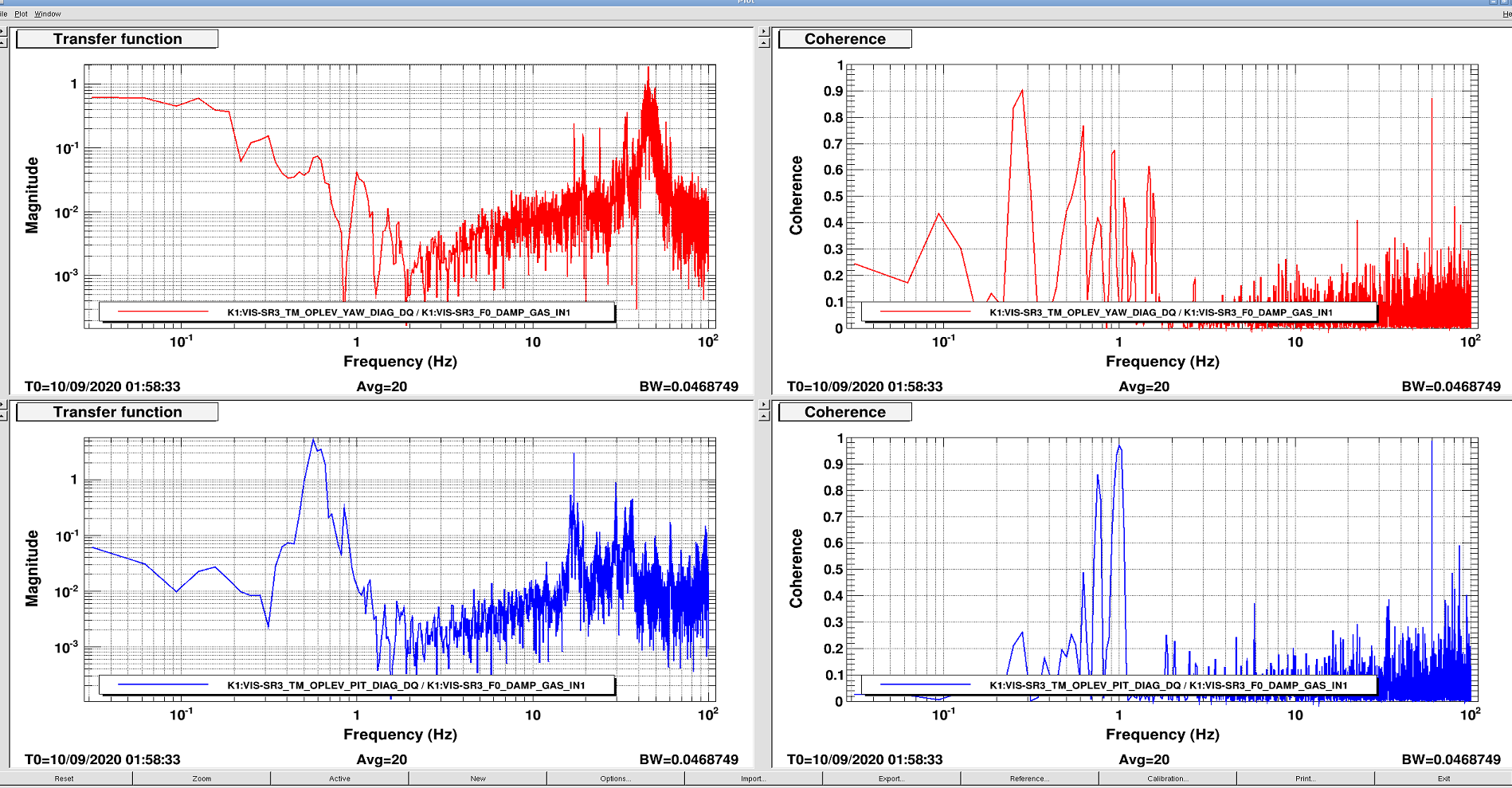
In SR3 and SRM I measured the transfer functions: F0 displacement → TM-Y, TM-P. The motion of the F0 keystone moves the SF w.r.t. the magnetic damper.
Results
See the figures.
YAW: the coherence of the measurements are not particularly different. Moreover, the one for SRM, which has the conector far away from the magnets, is a little bit higher below 1 Hz. in the SRM transfer function there is even a large peak at 1.34 Hz (IM-Y and TM-Y).
PITCH: the coherence of the measurements are very similar.
Conclusion
- The results suggest there is no aparent difference where the connectors are w.r.t the magnets. This means, the two positions may be equally not bad or equally bad for the coupling.
- The couplng from vertical to yaw might come mostly from the cables, not from magnetic forces. See 5850.
- More investigation is needed using DC displacements as the ones reported in entry 5850.
Files
/kagra/Dropbox/Subsystems/VIS/TypeBData/SRM/TF/Measurements/20200910/SRM_F02TMPY.xml
/kagra/Dropbox/Subsystems/VIS/TypeBData/SR3/TF/Measurements/20200910/SR3_F02TMPY.xml
