Reports 1-1 of 1 Clear search Modify search
VIS (BS)
fabian.arellano - 14:32 Thursday 06 August 2020 (14875) Print this report
Upper limit to the contribution to DARM of DAC and coil driver noise in the optic stage.

Summary

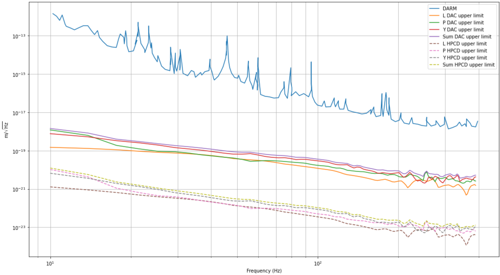
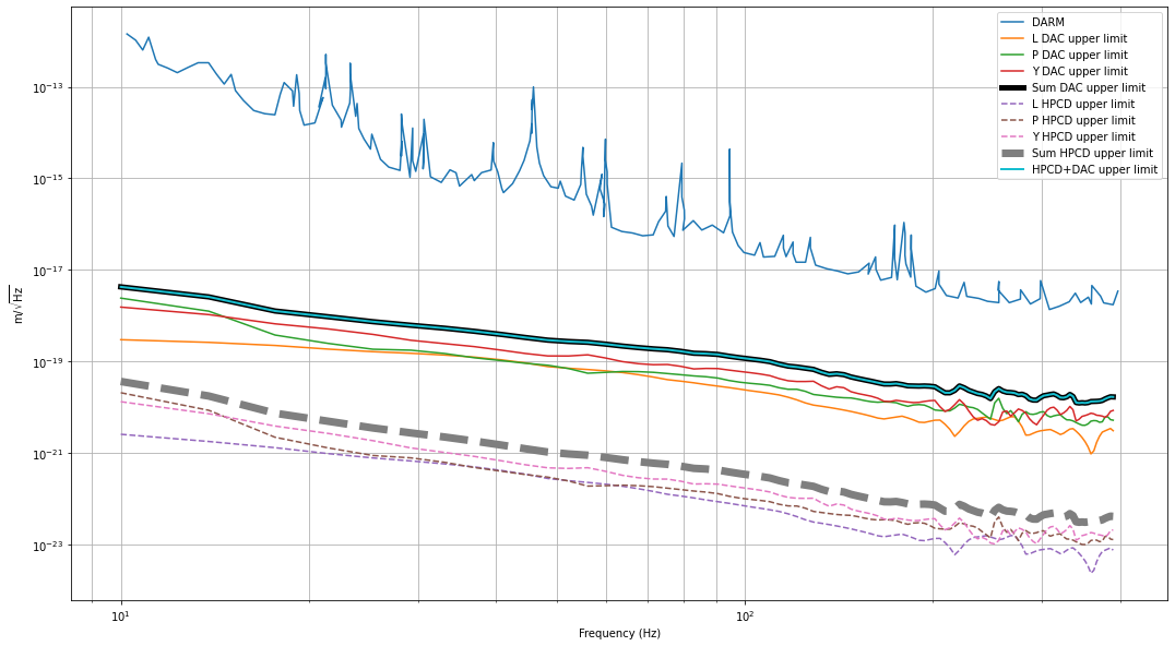
The calculated upper limits suggest DAC and coil driver noise are far below the value of DARM.

Some observations

We didn't measure the transfer functions (TFs) of the individual coils to DARM, we only measured the TFs from L, P and Y to DARM. Using this information I calculated upper limits in each DoF assuming the DAC and coil driver noise actuate entirely in that DoF. This is still a useful calculation as far as the upper limit is far away from DARM. In case it's close it would be useful to measure the TFs from the individual coils to DARM and then add the contributions in quadrature.

In the case of coil driver noise I used the LIGO value (JGW-T1503453) instead of the one Shimode-san measured (JGW-S1807823, entry 11949). The reasons are that

  • He measured the voltage at the output to coil with the circuit open and, therefore, there is no current noise flowing. Whereas this sounds like a good strategy for a voltage source the coil drivers are current sources which require the circuit to be closed for the current to flow.
  • The measurement is also referred to output not input where the DAC is.

I have the impression that the measurement we need requires

  • To close the circuit with a resistor to allow the current flow, measure the voltage across it and then calculate the current noise as I=V/R and
  • To refer the current noise to input where the DAC is to be able to use our TF measurement from the suspension DoF to DARM.  This requires  knowledge of the coil driver TF from input voltage to output current (in units is A/V). This TF would include the de-whitening filter plus any other gain.

Description of calculation

Ideally, what we need is the TF from the individual coils to DARM. However we didn't measure those so I calculate an upper limit by assuming the optic is constrained to move in one DoF only. In this conditions the form of the TF of the indivudual coils to DARM is very simple in either DoF:

  • In L: ( 1 / 4 ) * TFL→DARM
  • In P: ( 1 / 4 ) * TFP→DARM
  • In Y: ( 1 / 4 ) * TFY→DARM

Therefore, in either of the three cases the total noise is calculated by adding the contributions of the four coils in quadrature:

Sqrt(4) * (TF/4) * Noise = TF * Noise / 2,

where Noise is the noise of each coil referred to the DAC output. Notice this equation is the one Lucia used in her calculation reported in entry 13626.

Results

As shown in the figure both DAC and coil driver noise upper limits are far below DARM. I added the L,P and Y upper limits together as an additional overall upper limit.

  • I did the calculation using a Python script located in /kagra/Dropbox/Subsystems/VIS/TypeBData/BS/DAC_coil_noise/
  • The DARM signal I used is the one show in entry 13587. I extracted it using WebPlotDigitizer.
Images attached to this report
Comments to this report:
fabian.arellano - 14:55 Thursday 29 July 2021 (17687) Print this report

In the context of the O3GK paper, Kazuhiro Yamamoto-san and I reviewed the calculation of the effect of coil driver noise and DAC noise on DARM. The reason for reviewing is that I don't think we did it correctly back then and more discussion was necessary.

The effect of coil driver noise and DAC noise in DARM can be calculated as follows:

  • Measurement of the individual transfer functions from each coil to DARM,
  • Propagation of coil driver noise and DAC noise for each coil using the transfer functions and
  • Addition of all the contributions in quadrature given that the noise in different coil driverchannels and DAC channels are not expected to be correlated.

During O3GK the individual transfer functions from each coil to DARM were not measured, therefore, it is not possible to calculate the noise as described above. Nevertheless, transfer functionsfrom the virtual degrees of freedom L, P and Y of mirrors were measured and they can be used to calculate upper limits. The measurement of transfer functions in L, P and Y use well defined phase relationships between the signals in the different coils, whereas in the case of the actuation noise the phases are random. This difference yields an overestimation of the propagated noise. For example, when using the transfer function along L, it is implicitly assumed that the phases are sucht hat the forces from the coils move the mirror in the same direction along L at any given moment. In reality, however, the phases are random and produce forces that move the mirror in +L and -L simultaneously, yielding a motion with a smaller amplitude. As the same applies to P and Y, the total upper limit becomes

F_{i} = \left( T_{L} + T_{P} + T_{Y} \right) N_{i},          (1)

where i stands for either DAC or coil driver, N_{i} and F_{i} are the noise at the origin and the propagated one respectively and  T_{L}, T_{P} and T_{Y} are the transfer functions from actuation in L, P and Y to DARM respectively.

It is important to point out that in entry 14875 the formula

Sqrt(4) * (TF/4) * Noise = TF * Noise / 2

is wrong. As explained above, the different contributions of the individual coils should not be added in quadrature because the transfer function TF corresponds to either L, P or Y. It should be

4 * (TF/4) * Noise = TF * Noise,

which is where formula (1) comes from. Also note that the contributions from L, P and Y should not be added in quadrature either.

In the case of the BS, the calculation using formula (1) yields the attached plot.

I'll add the Jupyter notebook and the other files used in the calculation in the following directory:

/kagra/Dropbox/Subsystems/VIS/TypeBData/BS/DAC_coil_noise/

Images attached to this comment
Search Help
×

Warning

×