Calibration of MICH using feedback signal is done.
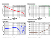
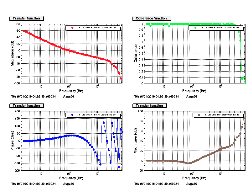
First attached graphs show a measured OLTF with coherence and calibration TF of G/(1+G). G: open loop transfer function
MICH noise N shows up at feedback signal as N G/(1+G). Multiplying the feedback signal with the TF of G/(1+G) and the pendulum TF of f^-2 can reconstruct an original noise N.
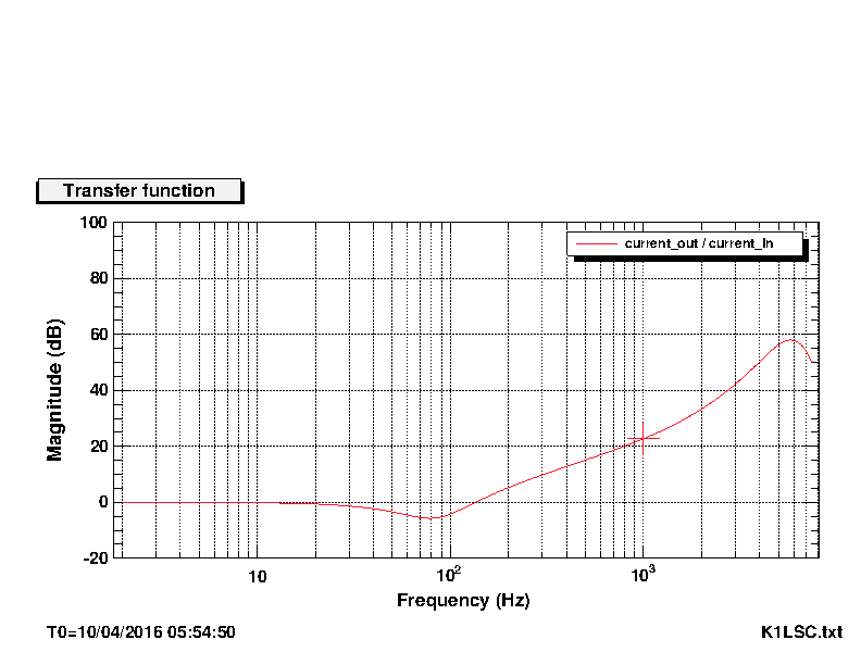
Another attached graph shows a simulated G/(1+G) by Foton using complex zero at 85Hz (Q=1.3), pole at 80Hz, zero at 2000, 2000Hz, with pendulum TF using complex pole at 0.93Hz (Q=4.85). This is being used to produce the calibrated time series sensitivity. However this TF is not fitted one, so it is not perfectly accurate. Specially above 5kHz, the shape is different because the target frequency is too high for a digital filter with the limited sampling rate with 16kHz.
Above 5kHz, G is actually affected by the software AA and AI filters, but it was not easy to measure it. I tried to compensate them in the calibrated sensitivity, but did not succeeded in by the same reason above, which is a limit of digital filters.I left it.
So this calibration is available below 5kHz.
I used 2.9e-12 as a conversion factor from counts to meter.
Note that too small conversion factor like 1e-9 was not applicable on real time series data due to the digit limitation of 4 bytes. I included only 2.9 of 2.9e-9 in the filter bank as a conversion factor uising Foton. So the unit of h(t) which is ]recorded as DAQ channel is nano meter (10^-9 meter).
Do not forget to divide it by 1e9 and 3000 if you need the strain sensitivity.
Calibrated h(t) shows up at K1:LSC-MICH_CTRL_CAL_OUT_DQ.
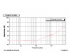
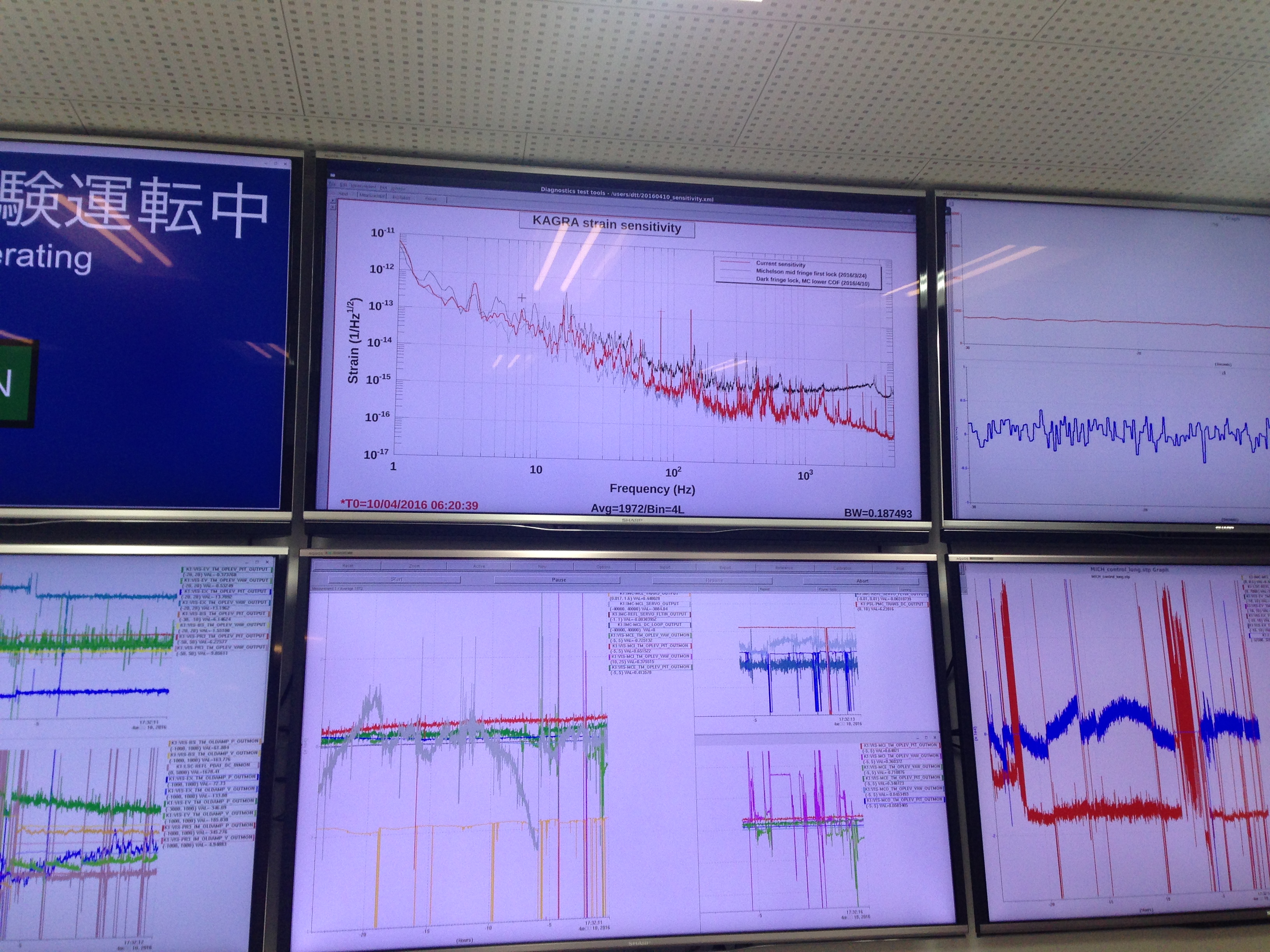
I also updated the main sensitivity screen in the control room (see attached picture). DTT file is saved as /users/dtt/20160410_sensitivity.xml
