[Koji Arai, Kokeyama]
OMC Scan Result
The incident light is with the X arm locked. OMC finesse was measued as roughly 580. The power in each mode is shown below.
| Carrier Sub tota | Upper 17MHz sidebands | Lower 17MHz sidebands | Upper 45MHz sidebands | Lower 45MHz sidebands |
|
order mW
CA0: 9.4
CA1: 0.38
CA2: 0.62
CA3: 0.26
CA4: 0.10
CA5: 0.015
CA6: 0.025Sub total
order mW
CA0: 9.247, 9.6409 => 9.4
CA1: 0.38
CA2: 0.62
CA3: 0.26
CA4: 0.10
CA5: 0.015
CA6: 0.025
Upper 17MHz sidebands
order mW
0 0.040
1 0.013
2 0.0026
Lower 17MHz sidebands
order mW
0 0.041
1 0.013
2 0.0023
Upper 45MHz sidebands
order mW
0 0.049814
1 0.014056
2 0.003407
Lower 45MHz sidebands
order mW
0 0.053
1 0.017
2 0.0043
|
order: mW
SB0: 0.040
SB1: 0.013
SB2: 0.0026
|
order: mW
SB0 0.041
SB1 0.013
SB2 0.0023
|
order: mW
SB0 0.050
SB1 0.014
SB2 0.0034
|
order: mW
SB0 0.053
SB1 0.017
SB2 0.004
|
See the detailed result in the attached text file.
Carrier Sub total
order mW
CA0: 9.247, 9.6409 => 9.4
CA1: 0.38
CA2: 0.62
CA3: 0.26
CA4: 0.10
CA5: 0.015
CA6: 0.025
Upper 17MHz sidebands
order mW
0 0.040
1 0.013
2 0.0026
Lower 17MHz sidebands
order mW
0 0.041
1 0.013
2 0.0023
Upper 45MHz sidebands
order mW
0 0.049814
1 0.014056
2 0.003407
Lower 45MHz sidebands
order mW
0 0.053
1 0.017
2 0.0043
Identified Modes
- See the previous post for the identified mode for carrier 0-3th order.
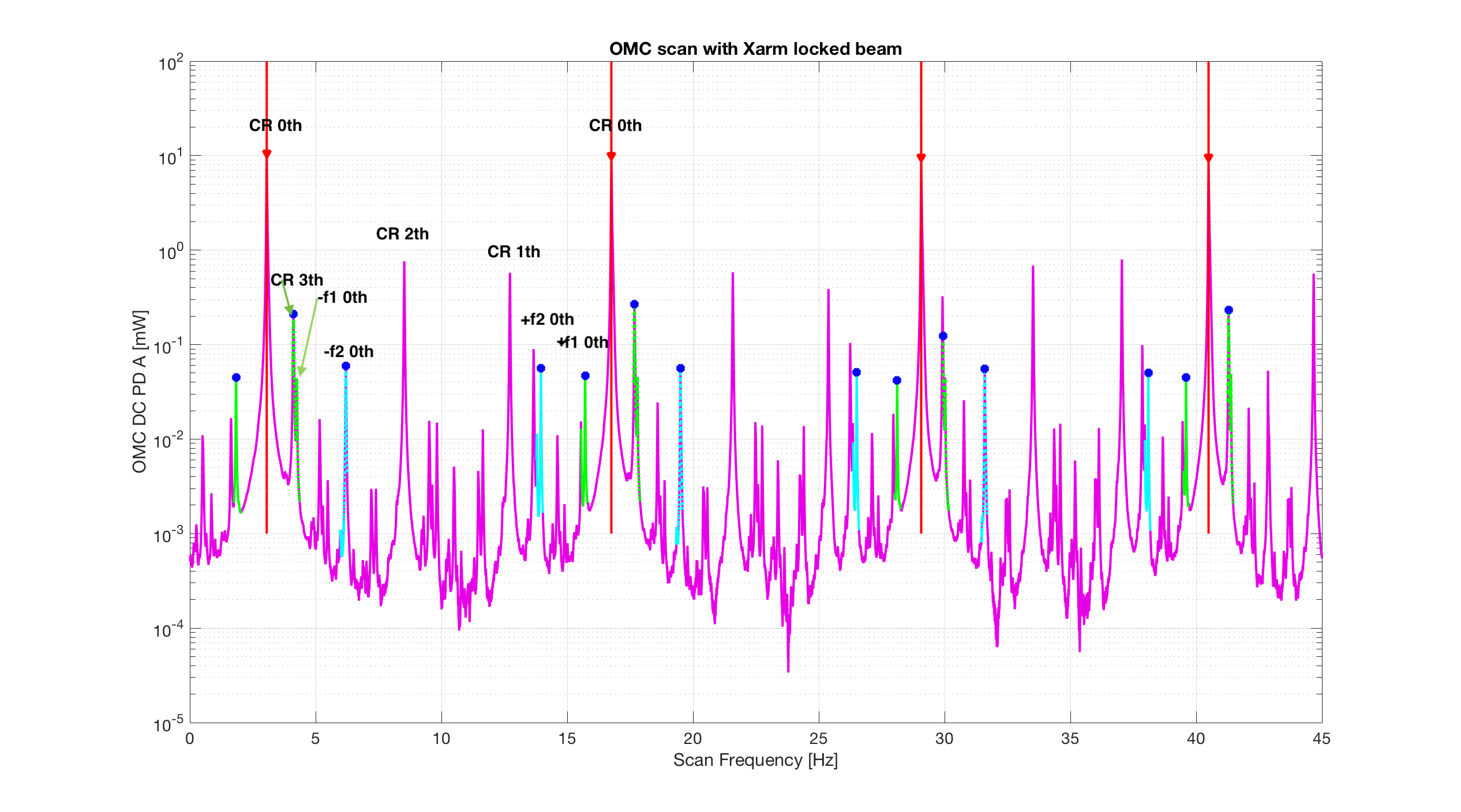
- Identified +-f1 and +-f2 sideband positions in the scan is shown in the attached first png figure.
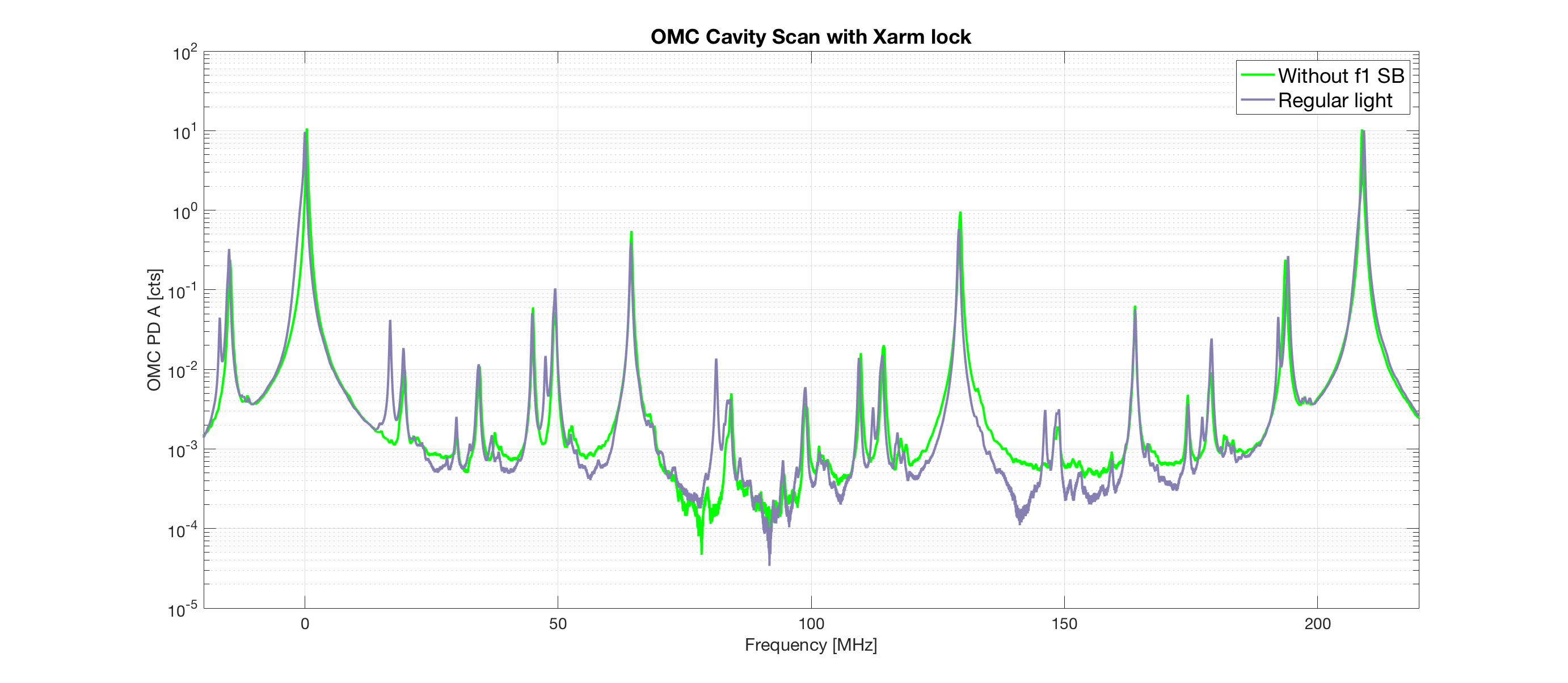
Varifying the identified Modes
- We measured the cavity scan without f1 sideband (with Nakano-kun's help in the mine). See the second png figure. Comparing with and without f1 SBs, peaks where f1 SBs should be correspond the assumed f1 SB positions shown in the first figure. Because the scan direction was opposite, the order sof the modes are flipped.
- For the carrier, see the previous post.
Fitted plot, detailed mode identification, and PZT-frequency calibration are attached as pdf.