At Mitaka.
Motivation
OSEM flags, especially on a mirror, easily falled off from the mirror, and OSEM flags on an IM sometimes broke. These accidents were the 2nd or 3rd cause why the installation of PR3 (or dummy PR3) delayed. KAGRA-VIS team wants to reduce the probability of such accidents. They estimated that the cause of the accident was the narrowness of the OSEM cavity for the flag. The cavity space is limited by both holder for LED and PD, and less than 2.5 mm each side of a flag (see the current drawing.) There could be many solutions. Here the easiest idea to widen the distance between the holders for PD and LED is tested.
Setup
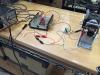
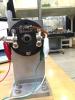
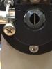
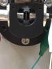
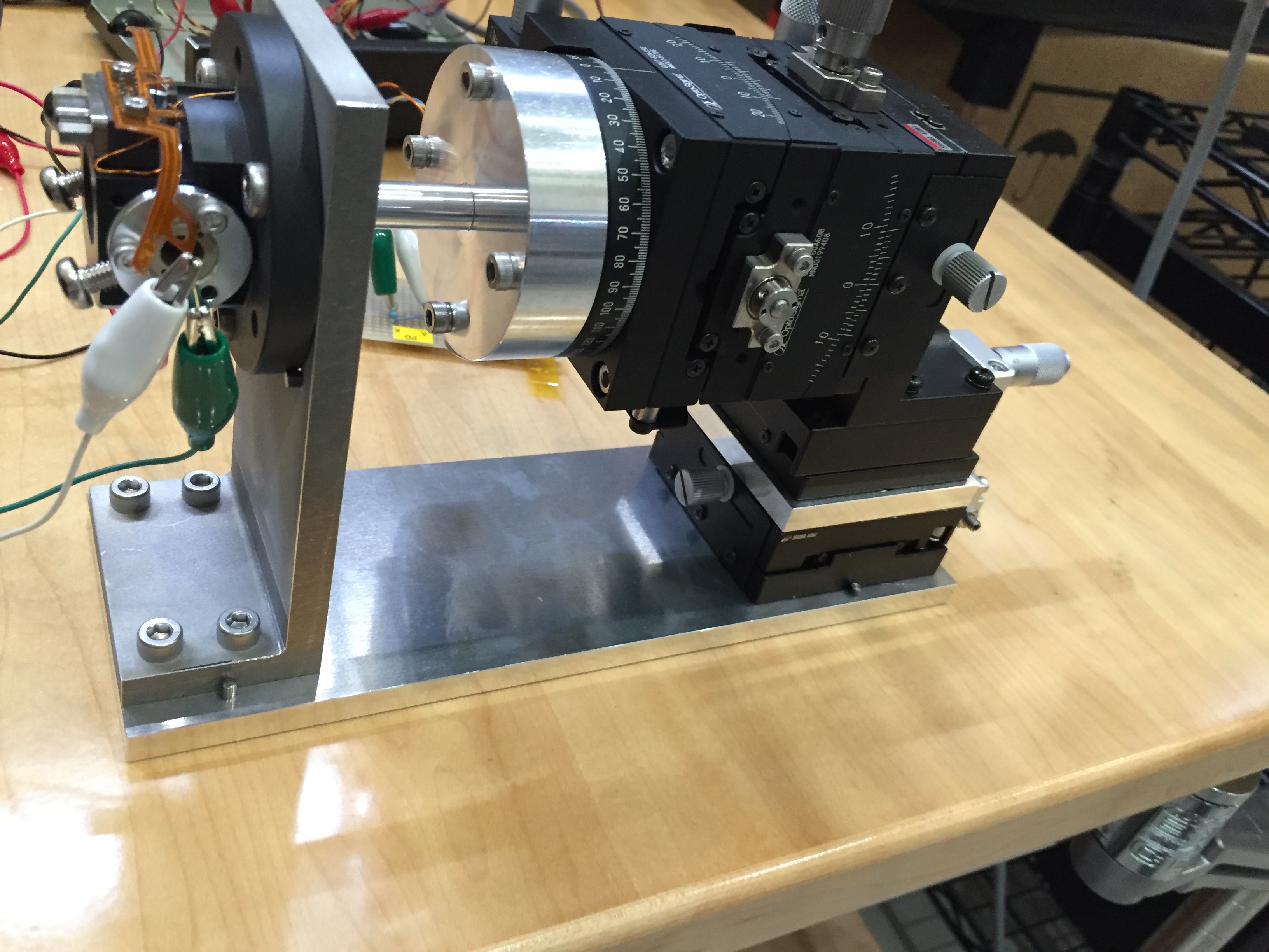
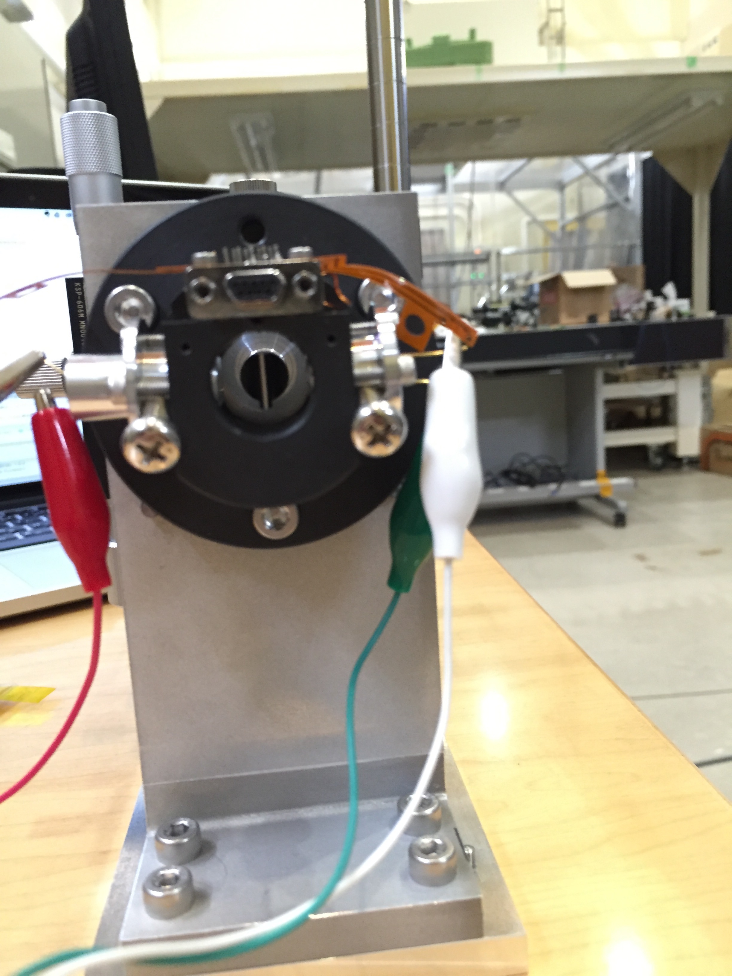
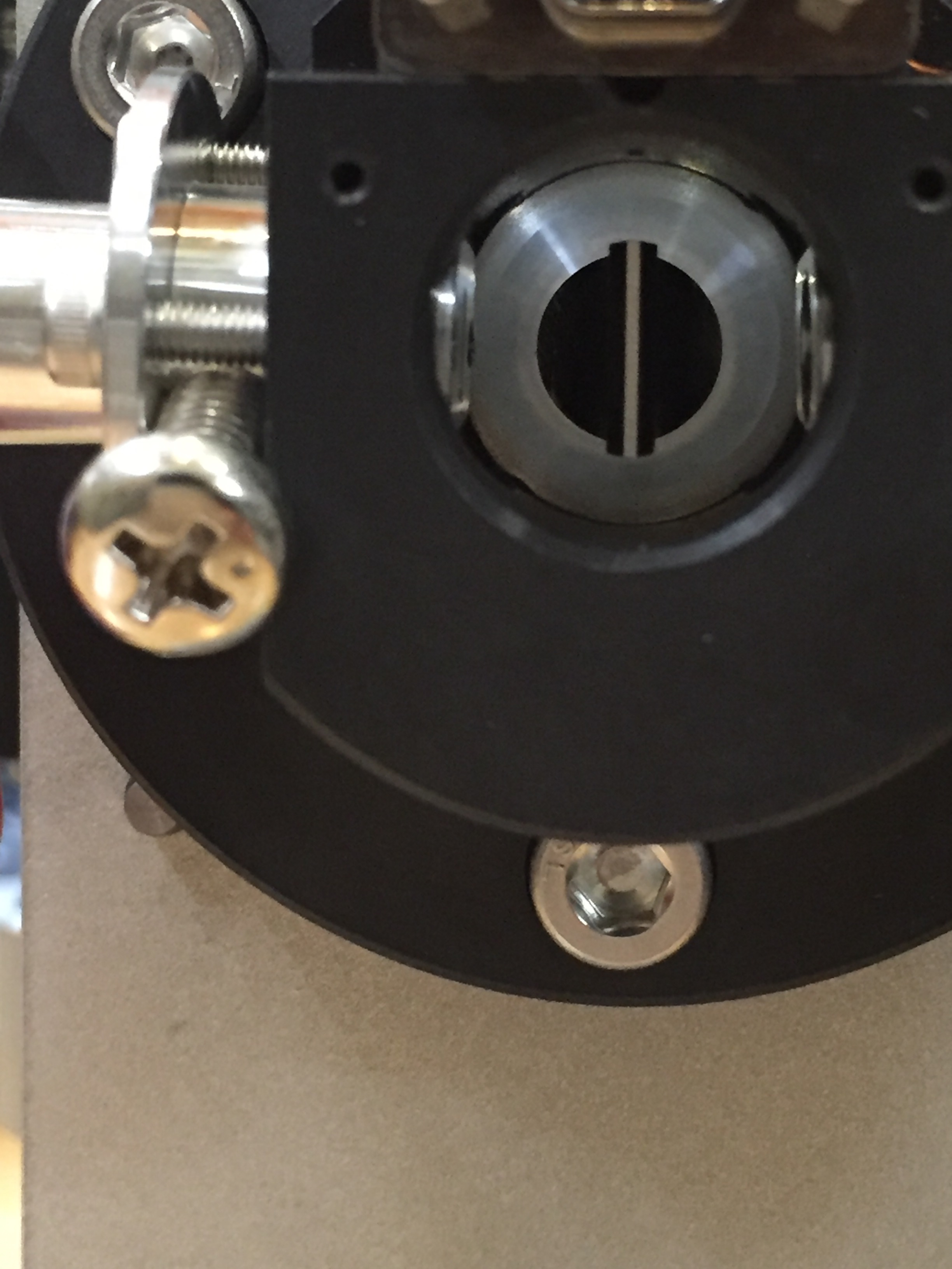
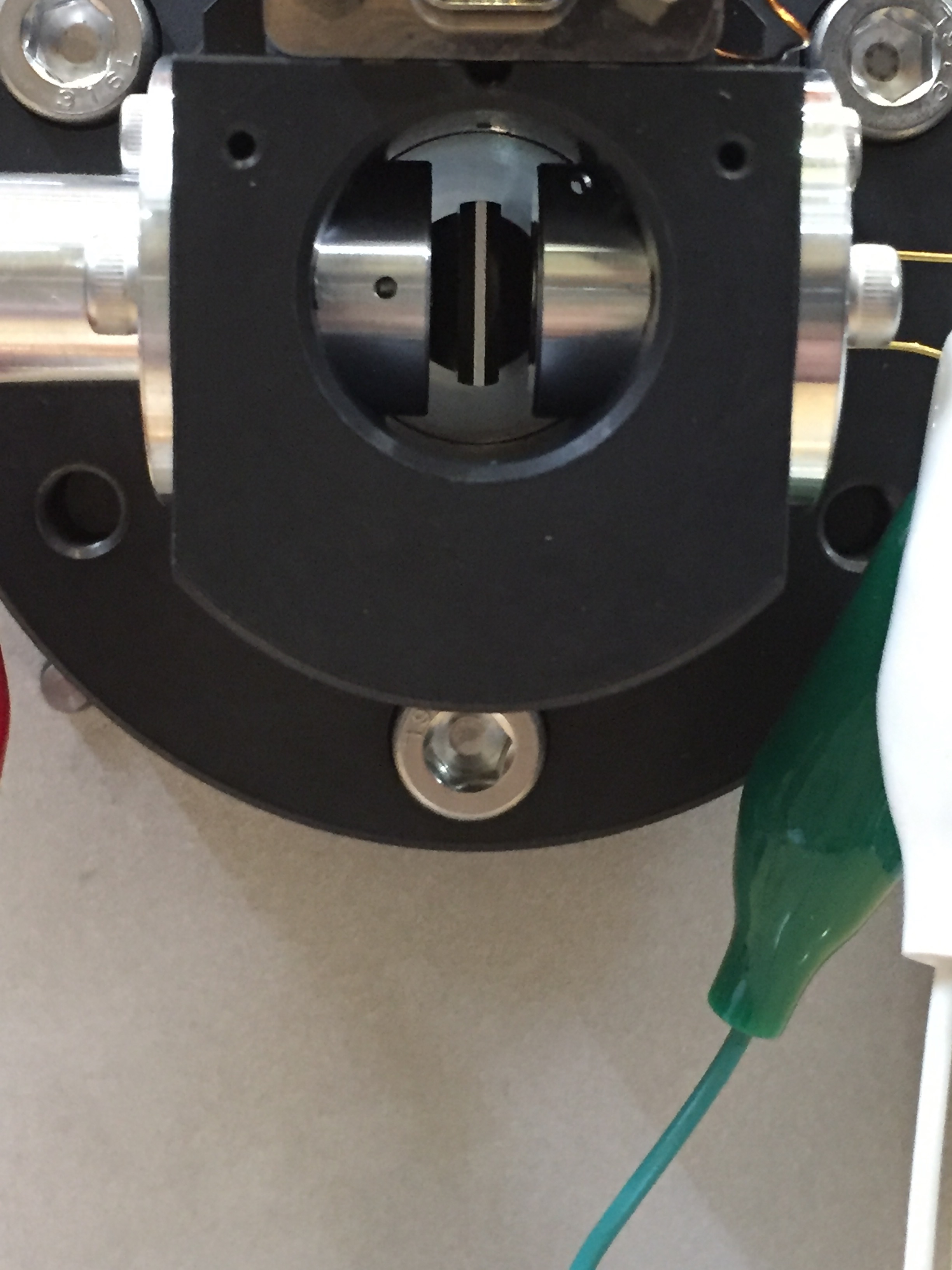
First the PD and LED holders were fixed to the OSEM body, making each holder 5-mm behind. A M5 screw was used to measure this distance for each side. Actually, the M5 screw is sandwitched with the LED/PD holder and the OSEM body. Then, as shown in the pic 4, the clearance of the OSEM cavity was maximized (compare with pic 5, the original cavity). The test bench (pic 1, 2, 3) with 6 DoFs actuators (micrometers) prepared by Ikenoue-san (and me) in NAOJ/ATC last year was used again. An OSEM driver made by Okutomi-kun and me last year was used again. Once a calibartion factor was measured with the setup, the M5 screws were removed, and then the PD/LED holders were fixed to the OSEM body in their nominal positions, and then again a calibration factor was measured for comparison.
Calibration factors
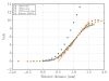
Calibration factors are shown in the Figure. Green (OSEM widen) and orange (OSEM normal reduce) circles should be compared. Because the distance between the LED and PD were different for the two conditions, the LED power read by PD was tuned to be similar when the flag was fully opened (9.4V and 10V for green and orange, respectively). As shown in the Fig, those two has the same tilts at their centers so calibration factors, as expected; accroding to the fittings, the tilts of green and orange are 8.45 V/mm and 9.08 V/mm, respectively. Probably these difference is due to the LED power read by the PD when the flag is fully opened (10/9.4 =1.06, and 9.08/8.45 = 1.07. I regret that I did not set exactly the same maximum value of the PD for the both conditions.)
Blue are the measurements without tuning the LED power; the power is the same as the one for green circles, but the LED/PD holders are fixed in their nominal positions. The PD got saturated before the measurement could be completed. It was dangerous to input too much power to a PD, I stopped the measurement as shown in the Fig. In addition, measurements of OSEM#12 performed with an actual OSEM driver circuit in the last December is shown with salmon circles in the Fig, and the calibration factor is 10.0 V/mm according to the fitting.
Conclusion and discussion
The OSEM with a wide cavity can be used replacing the current version . I guess a slit in front of the LED holder and a good beam profile LED, which had not been adopted in the original "KAGRA OSEM" but I somehow took the liberty of changing the design last year (and used in PR3 now), would somehow help the situation. I need to check noise level with an actual driver circuit. Coupling with other DoFs movements of the flag need to be also investigated.
