[Miyamoto, Hasegawa]
RF PD for IFO REFL channel has been installed.
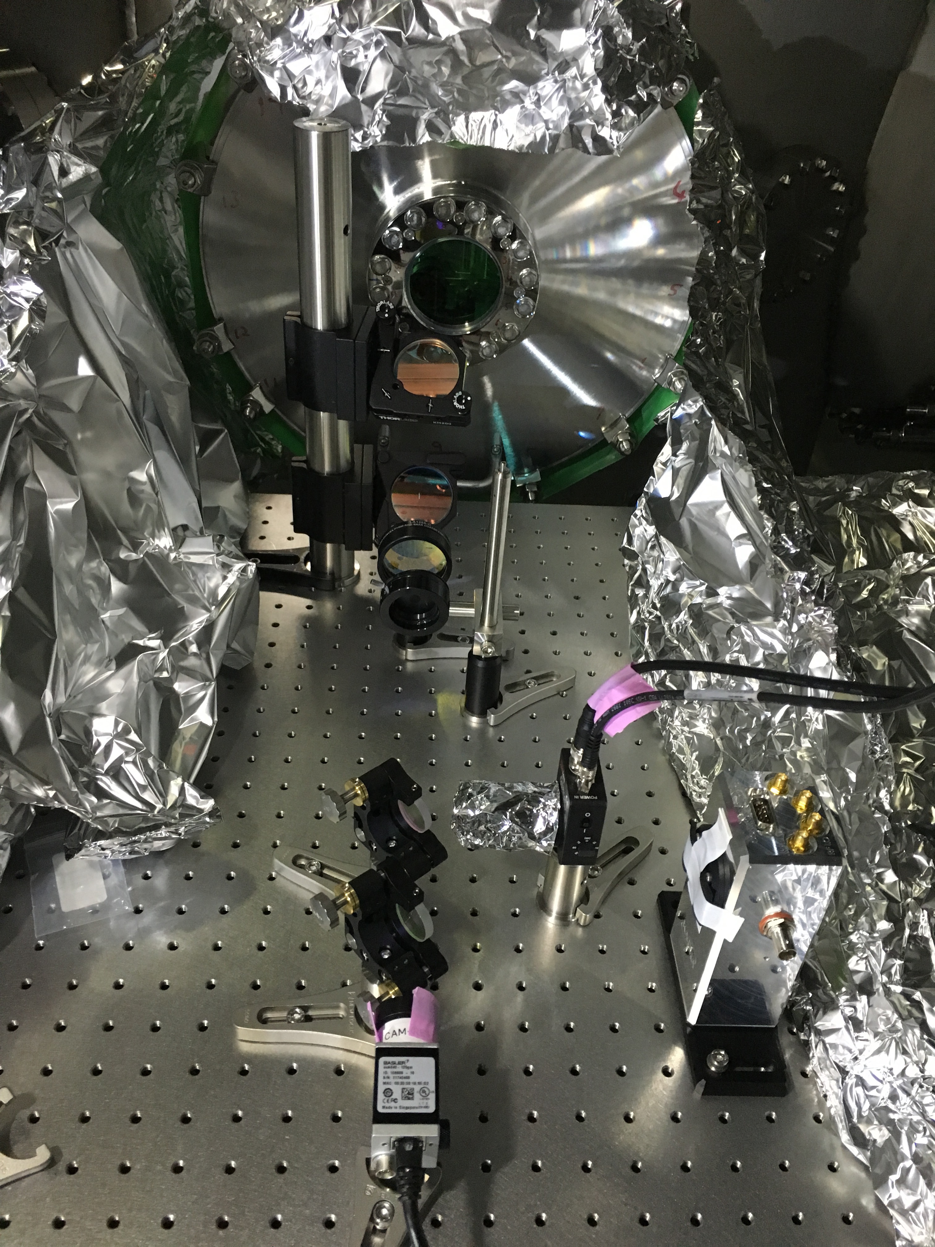
We put BS before camera and RF PD beside the thorlabs DC PD.(see attached picture ).
Because there were no space for pick off BS, we moved camera behind.
[Michimura, Nakano, Enomoto]
Today, we centered the REFL beam on the RF PD. Since the height of the beam at BS Hasegawa-kun et al. installed yesterday is too low compared to the photo-diode surface, we put a mirror just before the RF PD. In addition, since the beam is not focused, we inserted a lens (f=750 mm) between the BS and the mirror (noted above).
= Preparation for RF lock of MICH =
Then we completed the cabling around the RF PD and RF voltage source; connected a D-sub cable for power supply, and BNC cables for RF output and DC output to the RF PD, and connected BNC cables from the RF voltage source (located in IOO rack) to EOM (in PSL room) and to the demodulator (in IOO rack).
NOTE:
-- when connecting the cable for power supply to the RF PD, we once turned off RF PD interface, connected the cable, and then turned it on, to avoid half supply of voltage. Half supply will break RF PDs with high probability (for example see klog 633).
-- RF voltage from the source is splitted to EOM and LO by a power splitter just after the RF source.
-- RF signal from the RF PD is connected to the demodulator.