[Yokozawa, YamaT, Nakano]
New recode: 655 kpc

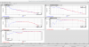
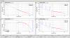
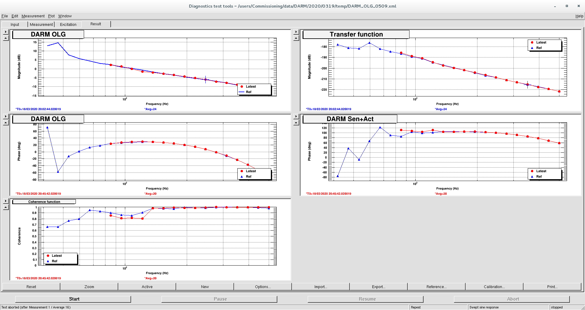
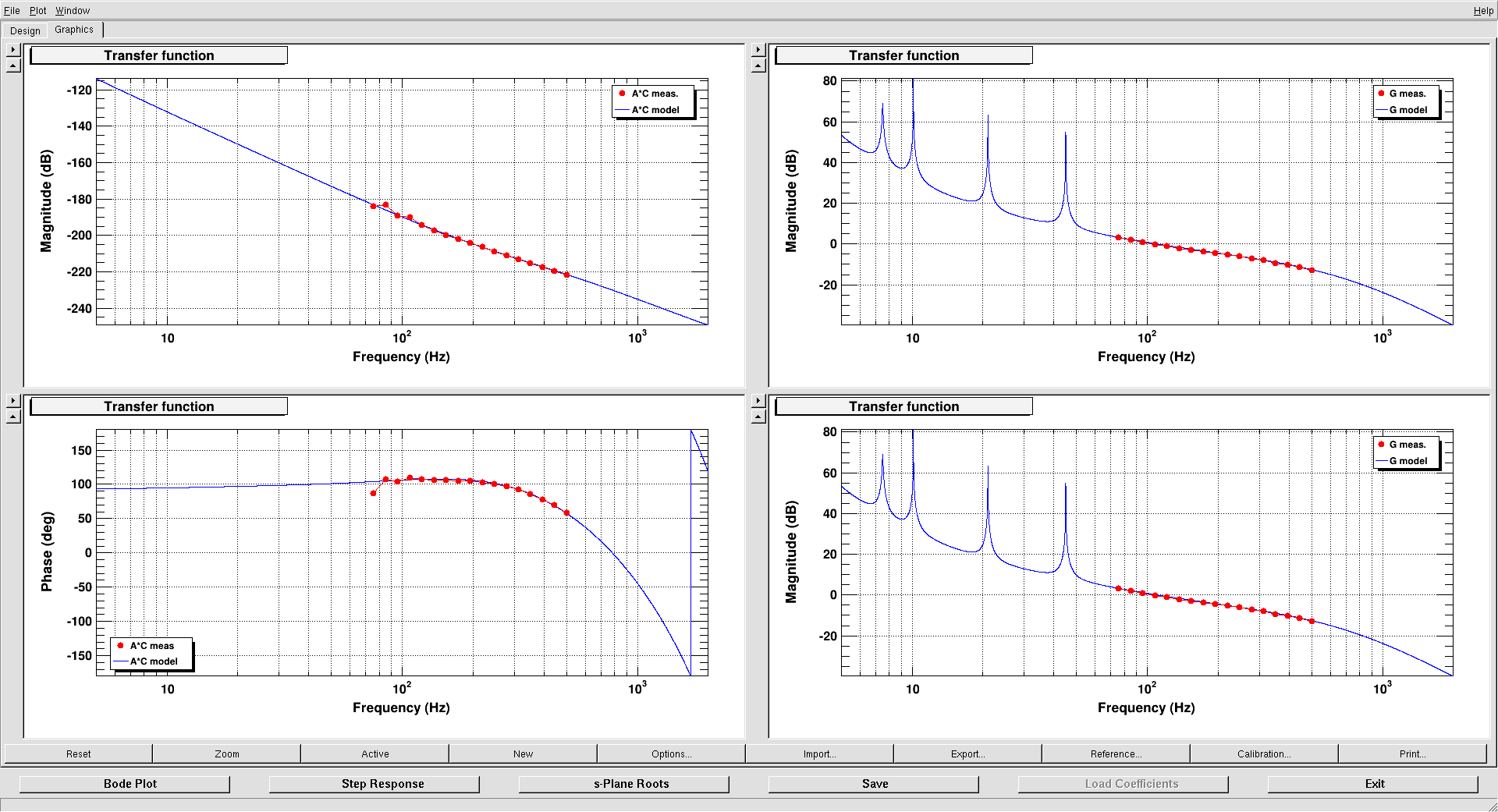
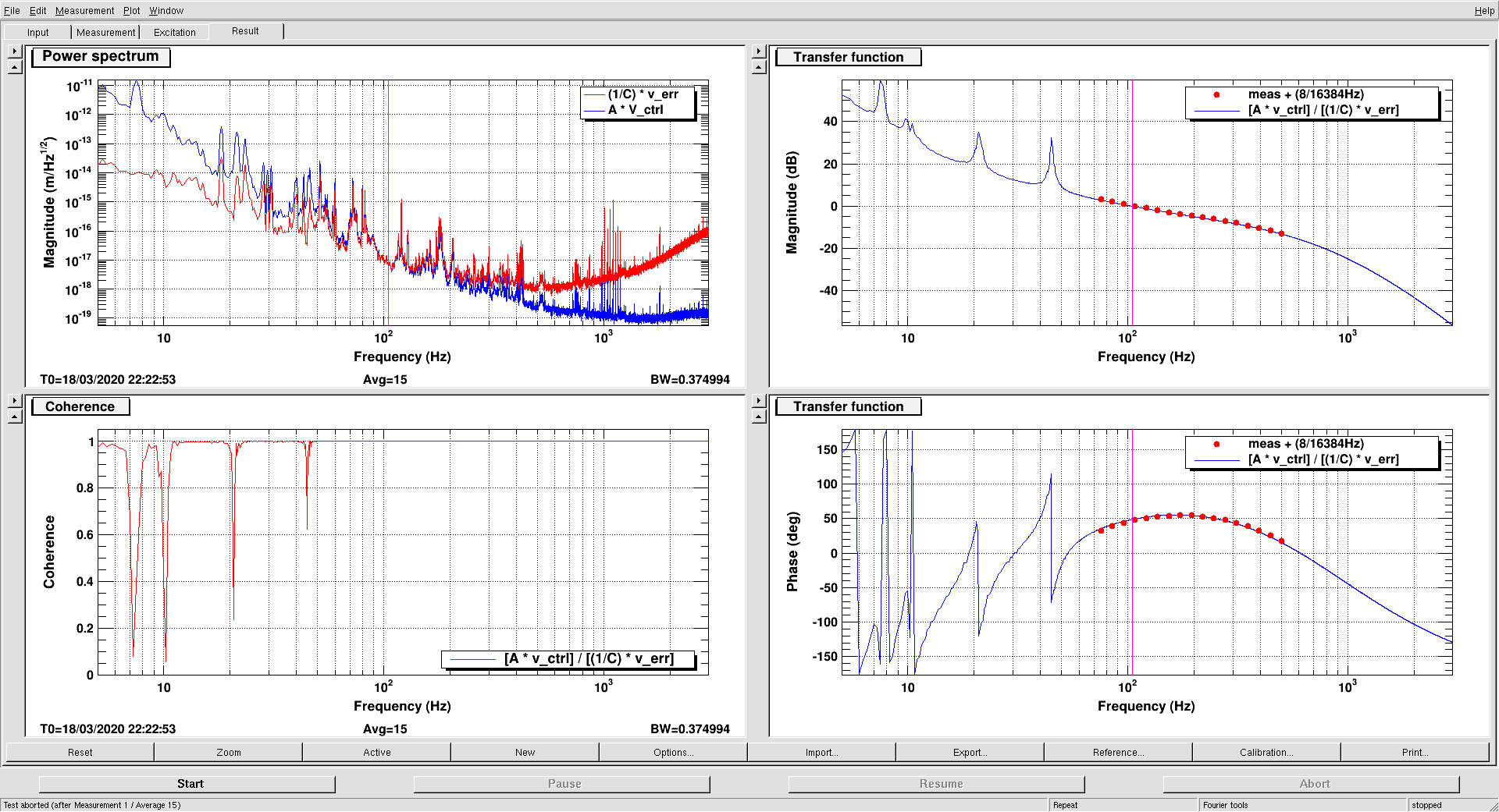
The calibration might not be correct sometime. Note that you have to measure the OLG when you want to report the sensitivity. The template can be open from the spectrum analizer symbol located in the right bottom of commissioning dock, and if the curve is fit to the blue reference, the calibration is correct.
- Dewhitening filter could be engaged without offload of the feedback on ETMs in the PRFPMI_LSC_LOCKED_RF. We guess this is thanks for the stabilization of several items, and the quiet wether. I implemented the guardian.
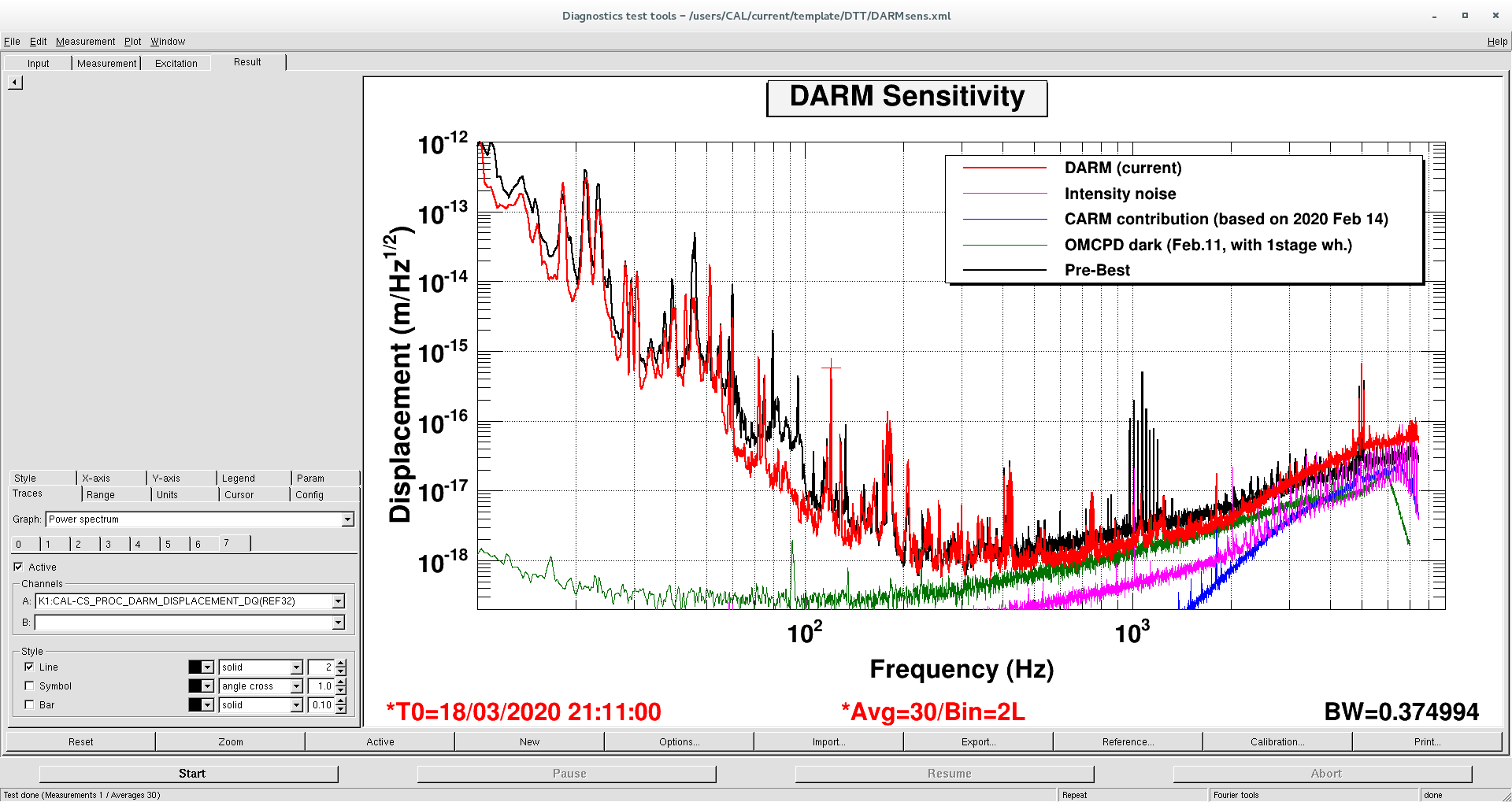
- However, the de-whitening filter did not improve the sensitivity. The second attached plot shows the DARM sensitivity with dewhitening (black) and without dewhitening (red). There is almost no difference.
- Shot noise was improved by imcreasing the laser power up to 5 W and the OMC DC offset to 20 mW.
- I found that the calibration is not really correct, due to the optical gain difference. This caused by the wrong normalization of DARM signal with the laser power. Although the dinamical normalization of the DARM with the main laser power using the sqrt of the laser power, the static normalization with the channel of K1:LSC-PSL_PWR_SCALE_OFFSET was used the liniar value of that. So, if you increase the laser power before the state of 'SET_LASER_POWER_NORM', the calibration was wrong. This is my fault, but we should realize that at some point easily by measuring the OLG and make sure the optical gain. Again, please measure the OLG often to check the calibration.
- That normalization was fixed by guardian.
- The sensitivity strongly depends on the arm alignment. As you can see the plot, below 100 Hz was improved a lot, and this reasion is strongly depended on the arm alignment.
- Also, 1Hz oscillation suffering us has gone in the good alignment. So, I concluded that 1 Hz oscillation is caused by the positive feedback loop due to the radiation pressure and the pitch motion caused by the 1 Hz length motion. If the alignment is bad, and the intracavity power is sensitive for the pitch motion of the mirror, the radiation pressure will push the mirrors at 1 Hz and enhance the pitch motion of 1 Hz. So, we should implement the ADS of the arm cavities and the beam position centering loop of ETMs.
- We should consider about the line frequency, especially the MICH line, PRCL line, BS ADS pitch line, and PCAL line at around 100 Hz. The sidelobes seem to contaminate the sensitivity.
