[Ushiba, Kokeyama, Nakano]
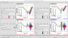
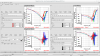
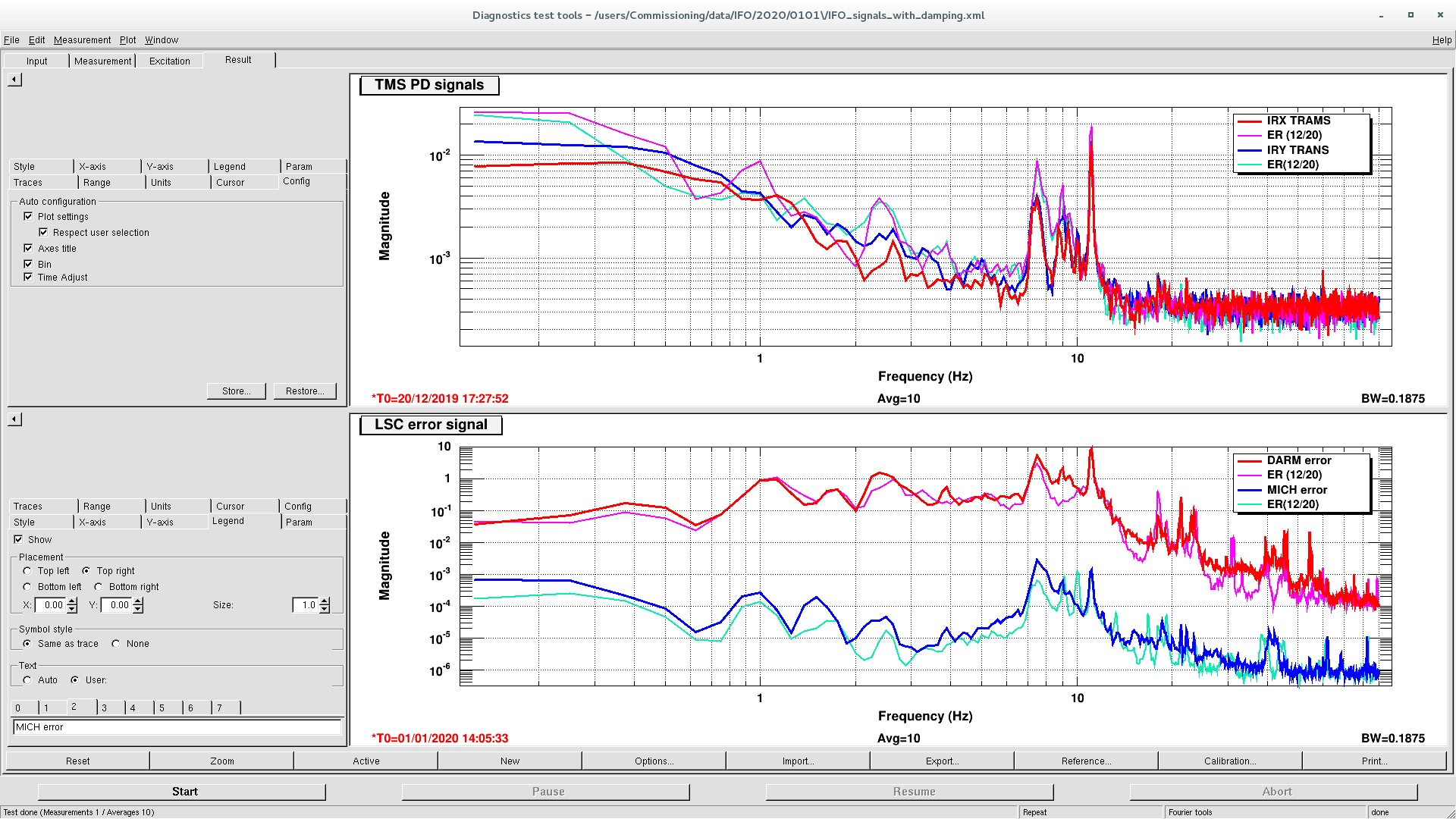
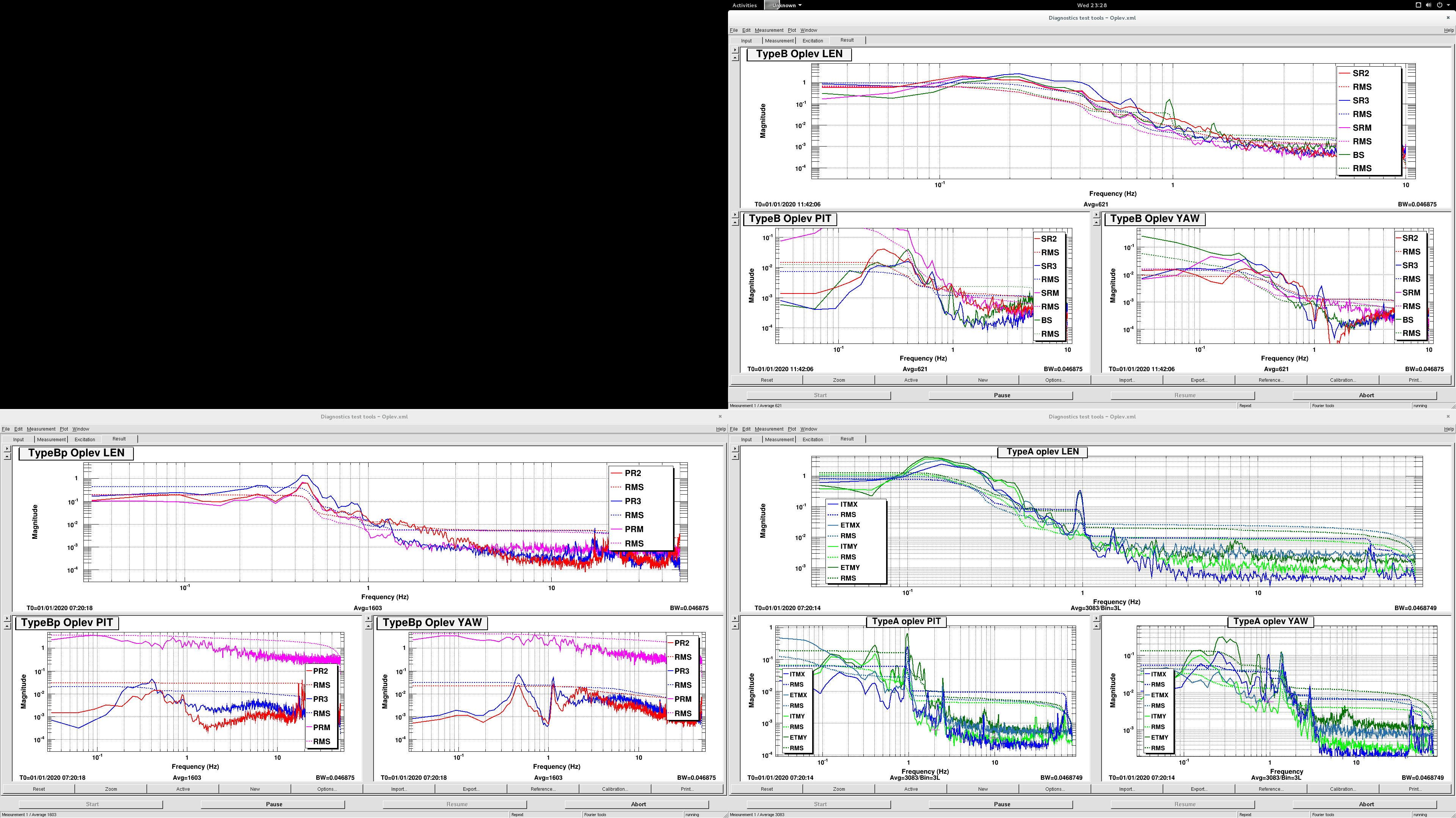
In the last couple of days, we implemented a new suspension control scheme for all suspensions as shown in JGW1911129. The suspensions are much quieter than before. All suspension angular motion is less than 100 nrad, even 50 nrad for several suspensions.
The control concept is as follows:
0. General concept.
- Oplev loop UGF: several Hz
- ASC feedback point: Error point of the oplev loop (Terrence path)
- No individual difference in each type as much as possible. [Important!!]
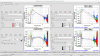
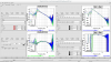
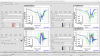
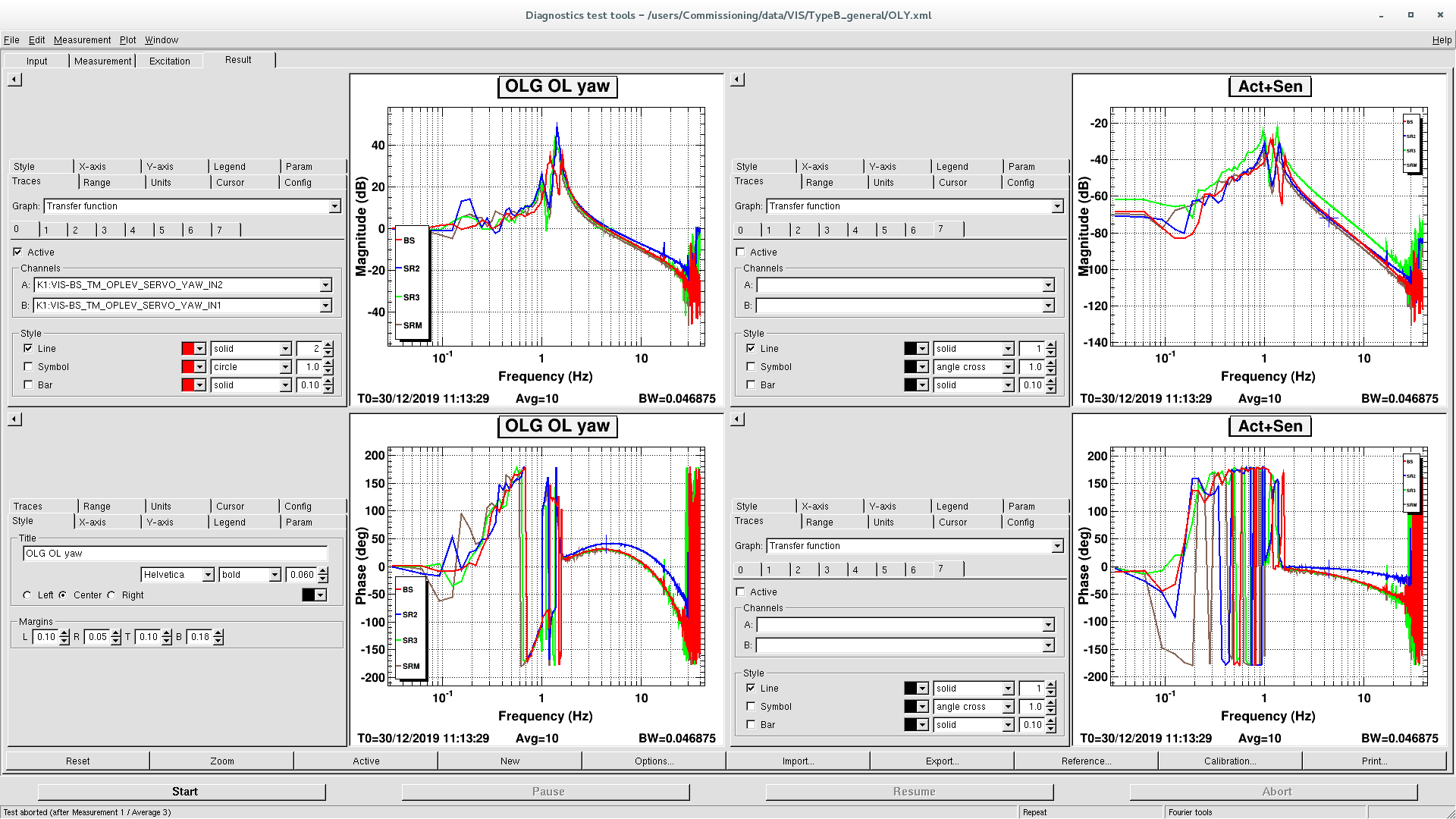
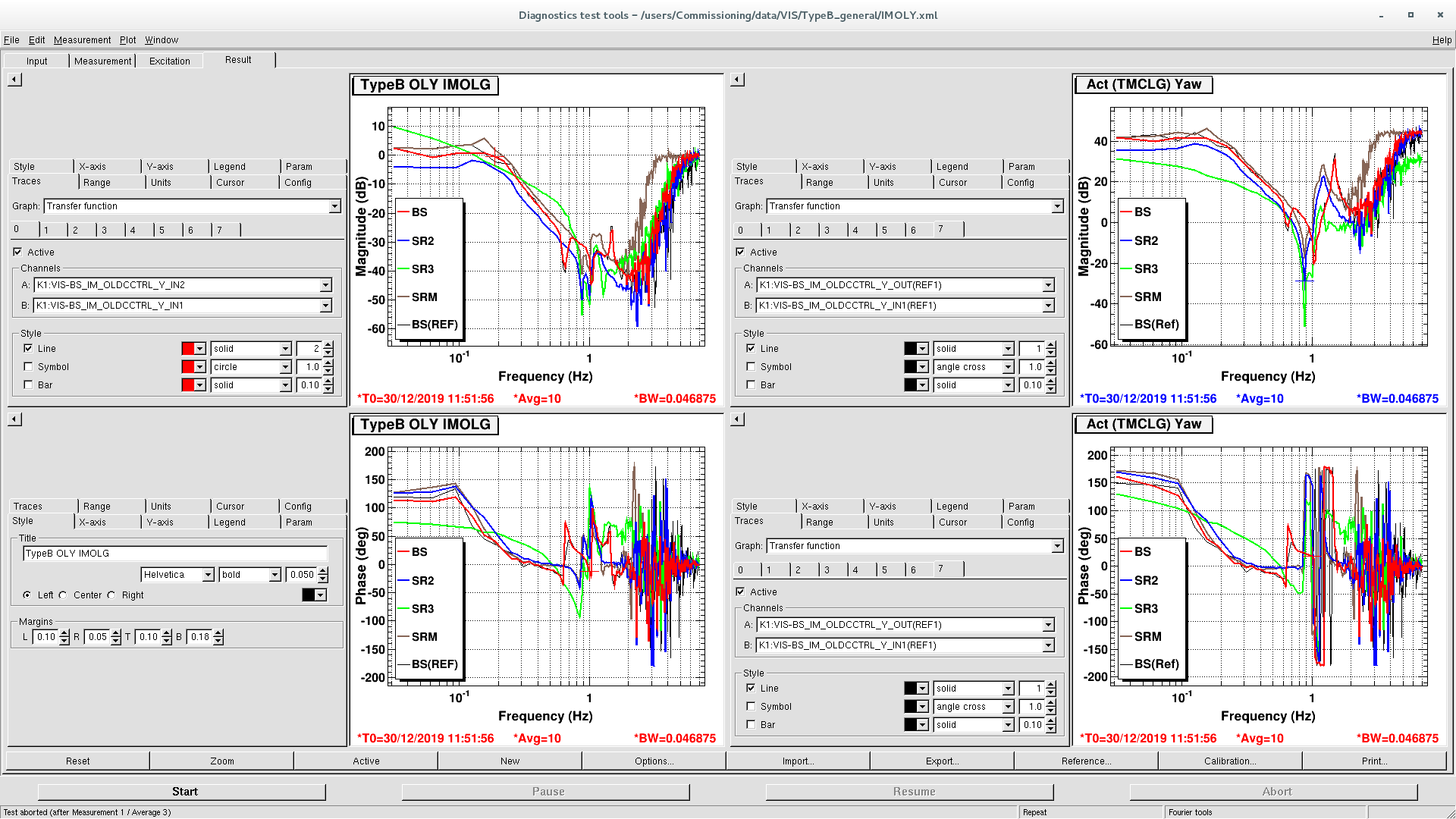
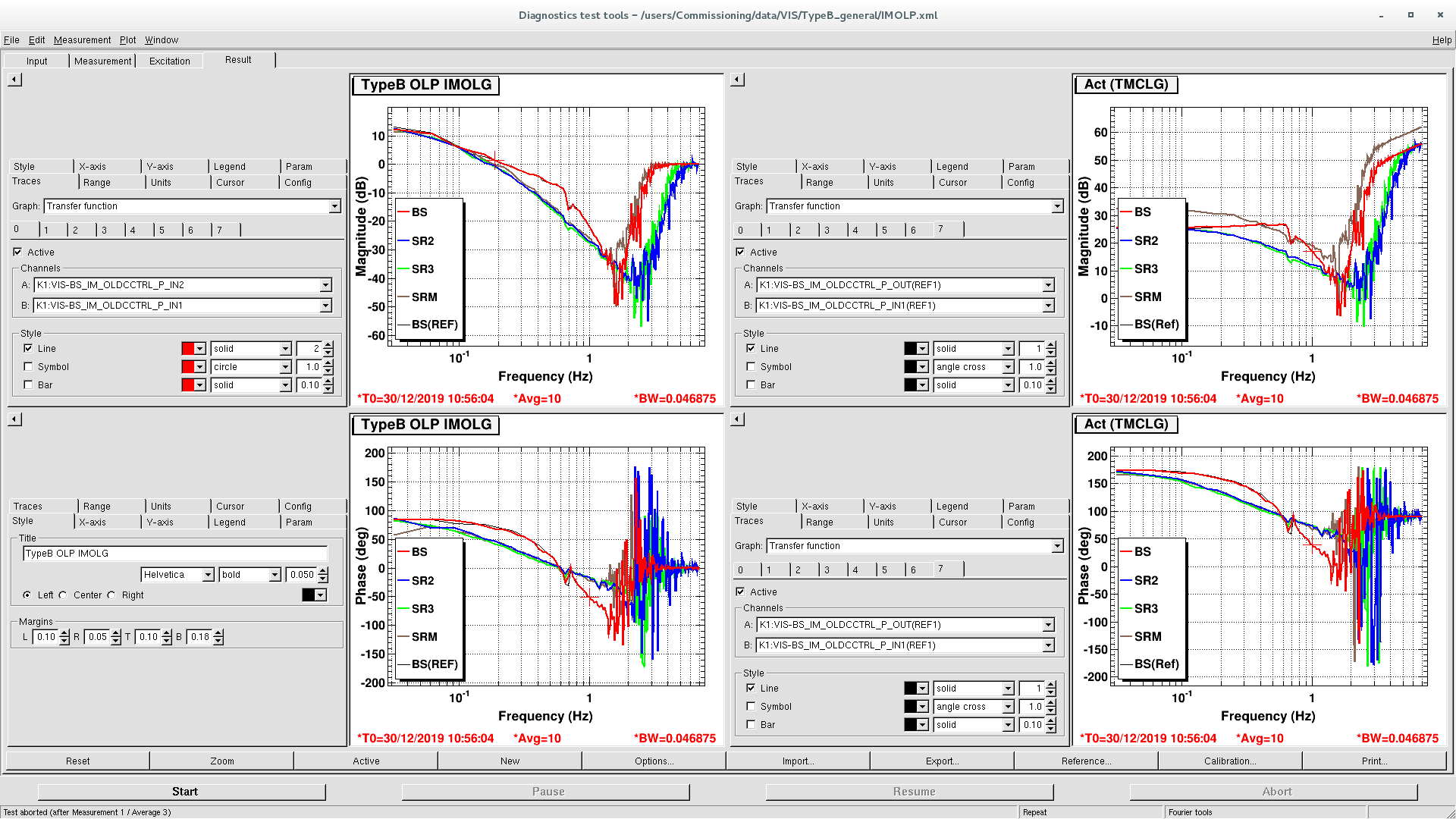
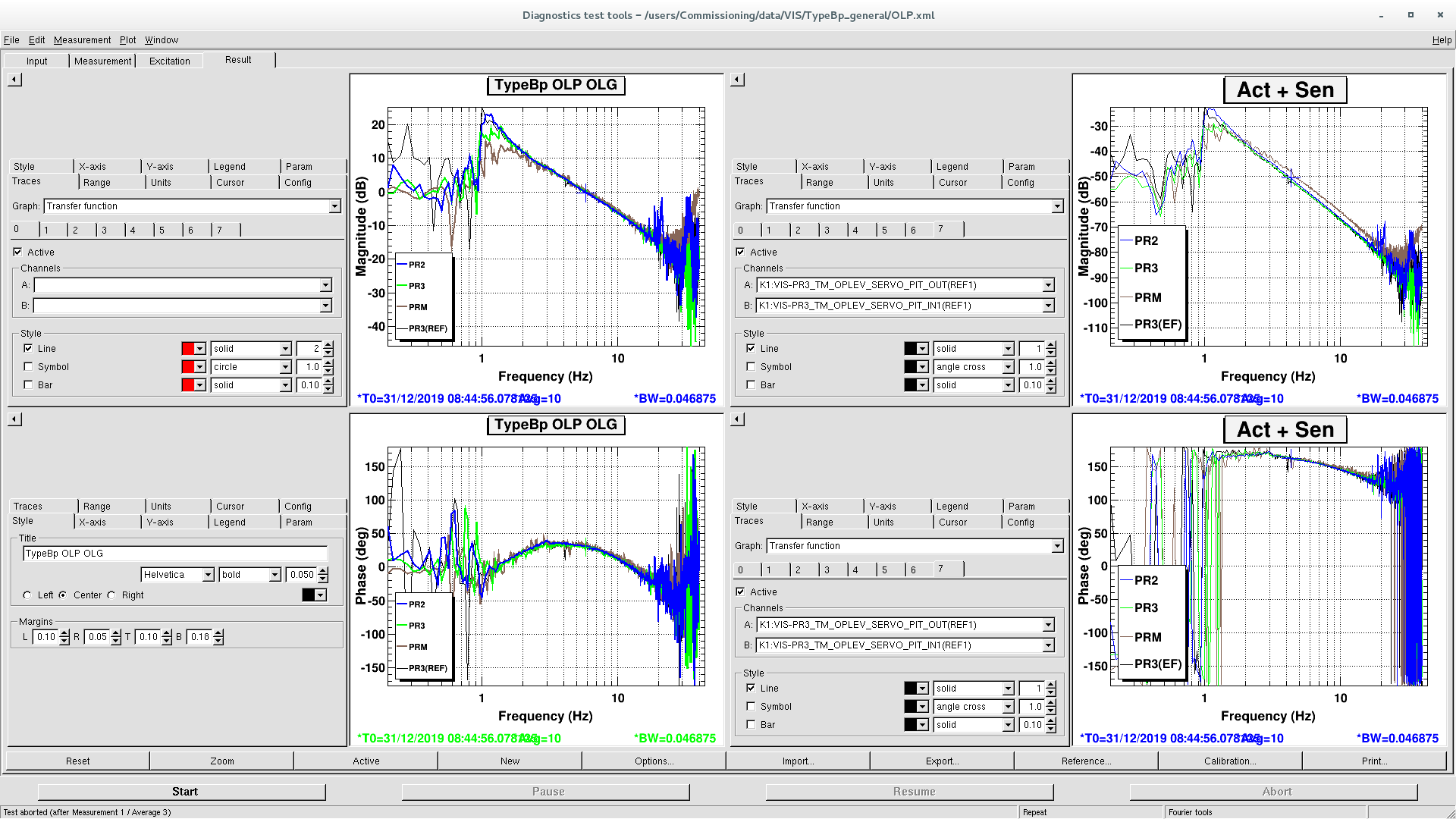
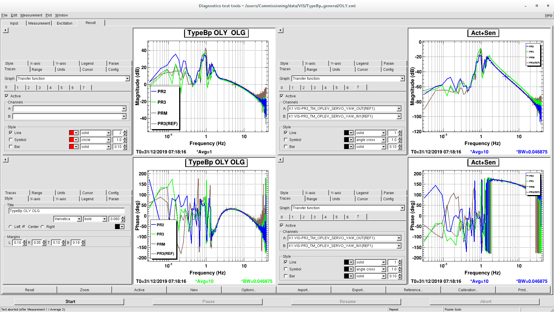
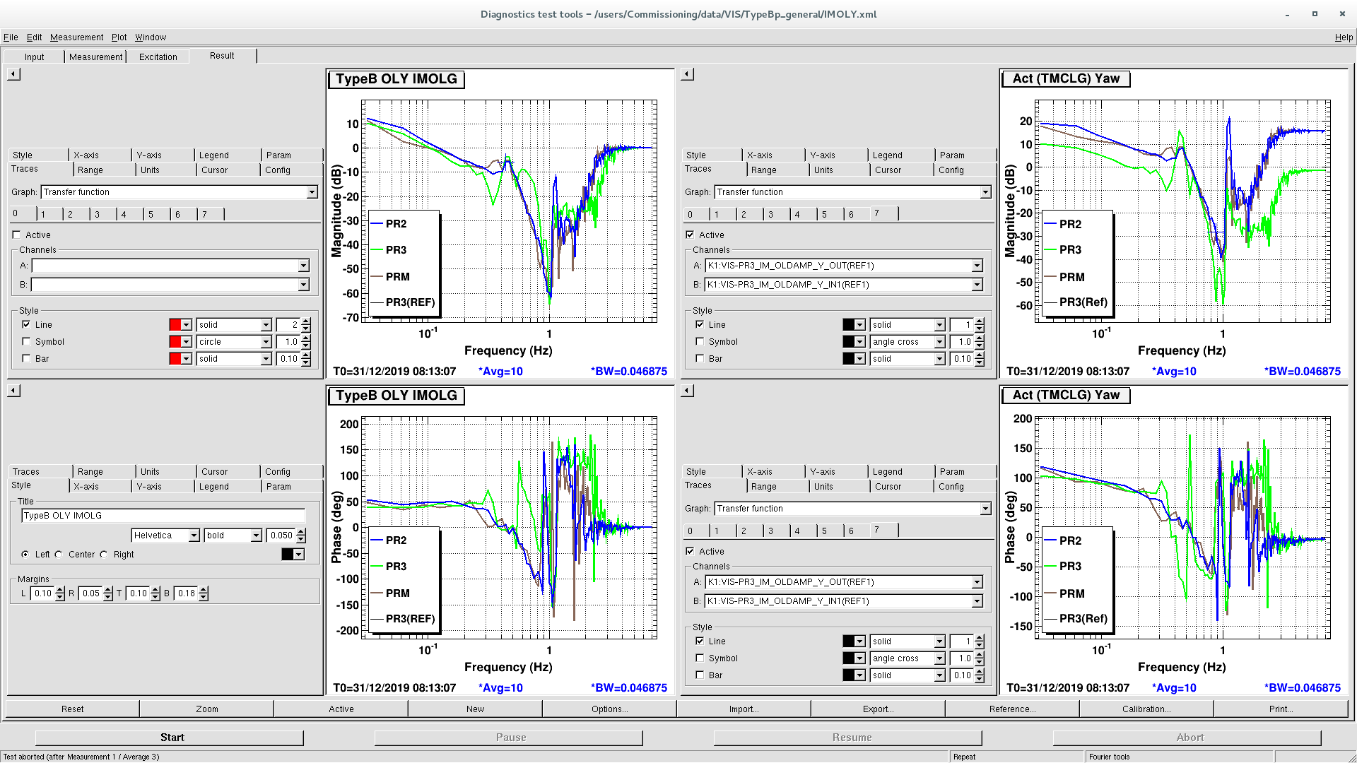
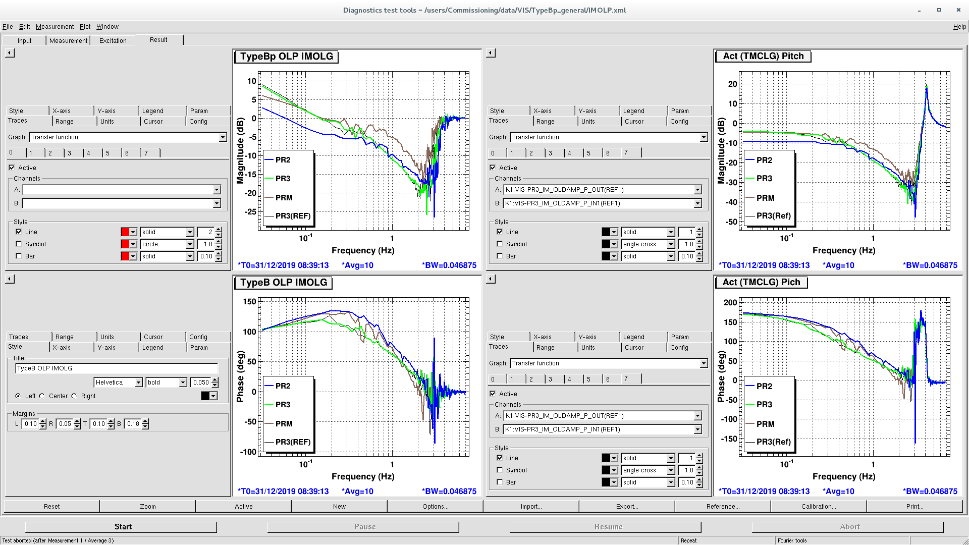
1. TypeBp, TypeB
- Control scheme
Feedback the oplev signal to the TM and load-off DC to the IM.
- UGF:
TypeB pitch: 5 Hz
TypeB yaw: 4 Hz
TypeBp pitch: 5 Hz
TypeBp yaw: 6 Hz
- Common servo filter: TM_OPLEV_SERVO. It contains as following filters
- Lead filter: single zero-pole pair lead filter.
- AC couple filter: HP at 0.1 Hz. This is enabled in the first sequence of closing the loop, then disable with a ramp time of a few seconds.
- boost: single zero-pole pair for typeB and a complex zero-pole pair for typeBp
- roll-off: elliptic filter at a few tens of Hz.
In addition to them, they also have resG or notch.
- IM load-off filter: IM_OLDCCTRL(TypeB), IM_OLDAMP(TypeBp)
Basically simple integrator. Some of the loops have lead, notch, an inverse filter of a suspension response. Cross-over frequency is around 0.2 Hz.
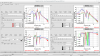
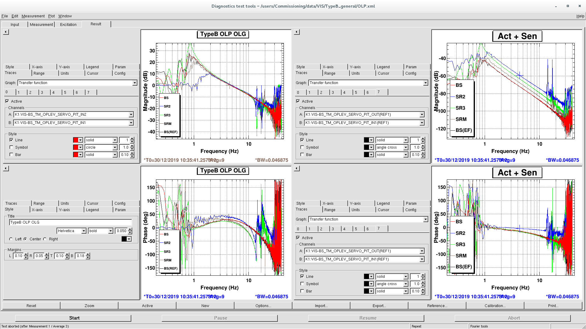
- OLG is shown as OLP(oplev loop pitch), OLY(oplev loop yaw). IM loop OLG is also shown as IMOLG
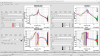
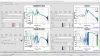
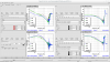
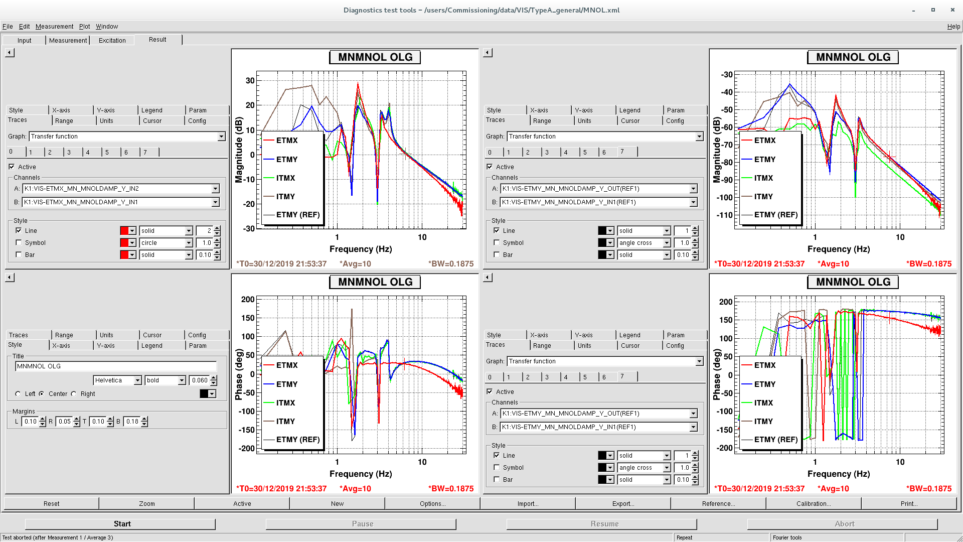
2. TypeA
- Control scheme:
(pitch): Feedback oplev signal to the IM and load-off the DC to the MN.
(yaw): Close the MNOL loop with an integrator. Feedback TM oplev signal to the error point of the MN loop.
- BPCOMB is also engaged.
- UGF:
MNOL yaw: 6.5 Hz
TMOL pitch: 2 Hz
TMOL yaw: ? Hz ( Forget. I will measure it again soon.)
- MNOL loop servo filter: MN_MNOLDAMP. It contains as following filters
- Lead filter: single zero-pole pair lead filter.
- null: gain of 0. This is enabled in the first sequence of closing the loop, then disable with a ramp time of a few seconds.
- int: integrator
- roll-off: elliptic filter at a few tens of Hz.
- Pitch common servo filter: IM_TMOLDAMP. It contains as following filters
- Lead filter: single zero-pole pair lead filter.
- AC couple filter: HP at 0.1 Hz. This is enabled in the first sequence of closing the loop, then disable with a ramp time of a few seconds.
- InvPen: Inverse of the suspension response
- boost: single zero-pole pair.
- roll-off: elliptic filter at a few tens of Hz.
In addition to them, they also have resG or notch.
- Pitch MN load-off filter: MN_OLDAMP
Basically simple integrator. Some of the loops have lead, notch, an inverse filter of a suspension response. Cross-over frequency is around 0.2 Hz.
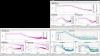
- I attached MNOL loop OLG only. We will measure them later.
Notes
- TypeA pitch loop has a room of modification. The phase margin seems not to be optimized.
- We also modified local damping filters. We need to damp each mode first with local sensor, then the oplev loop can be closed very easily.
- I feel like to look into the local damping loop of the TypeB, TypeBp.
- I'm wondering if we really cannot use the local sensor for typeAs. If we can, we can escape from BPCOMB.
- For oplev servos, we remove individual differences as much as possible. This makes it easy to maintain them. We also need to unify the local damping loops.
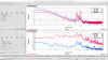
- I made a template for each loop to measure the OLTF, and oplev spectra under /users/Commissioning/data/VIS/Type*_general. I forget which is the proper folder to store them. We have to make all of the loops, and it helps the health check of the suspensions a lot, e.g. We found that the ETMX MN actuator response has additional pole or phase delay than the others.
- Guardian is also implemented for all suspensions. I modify it a lot. I will report it later again, and if you have any questions about that, please let me know.