Reports 1-1 of 1 Clear search Modify search
MIF (Noise Budget)
masayuki.nakano - 4:20 Wednesday 27 November 2019 (11775) Print this report
Frequency noise is limitting at high frequency

The frequency noise is limitting the sensitivity at high frequencies. We need to imcrease the laser power on the PD to improve the sensitivity at high frequencies.

- We rotated the HWP on the REFL table, and tried to maximized the laser power on the PD. Then we found the maximum is 2.1 mW with FPMI locked, according to the calibration (klog10917). The laser power should be 4W@IMC * 0.1^2@PRM * 1/4 (split into QPD and 3f PDs) = 10 mW without any loss. We need to check that there is no attenuator on the REFL table, but to explain the loss by arm cavity loss, it need to be 1000ppm. Of course we might have extra loss, but it seems to be large.
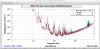
- We changed the laser power on the REFL PD by rotating HWP with FPMI locked, and measured sensitivity at several power. As shown in the attached figure, the sensitivity at high frequencies changes proportional to the laser power, so it indicates that the sensitivity would be dominated the frequency noise, and the noise source is the PD dark noise or the CARM servo noise.
- We only have a room of improvement by factor of 5 by increasing the input laser power in FPMI.crying

Images attached to this report
Comments to this report:
yutaro.enomoto - 12:48 Wednesday 27 November 2019 (11791) Print this report

Nice!

> - We only have a room of improvement by factor of 5 by increasing the input laser power in FPMI.

Probably we have more room of
- increasing the modulation index for f2 by a factor of a few, and
- modifying the RFPD circuit on REFL; let us remove R37 as Arai-san has been suggesting. This will lower the PD noise by a factor of sqrt(9), according to [kagra-isc 02129].

shinji.miyoki - 14:00 Wednesday 27 November 2019 (11795) Print this report

enomoto>- increasing the modulation index for f2 by a factor of a few, and

This modulation index improvement was drastic in CLIO. Actually, we could improve factor of 10 in sensitivity by just increasing modulation index (Too low modulation index was used in CLIO at the begining stage) . The ideal modulation depth  should creat sidebands whose power is comparable with the remained power in dark fringe state at PD, In the present KAGRA case where we have bad contrast, a huge modulation index is expected, however, anyway we might expect some improvement. We also consider about the slight or nonnegligible beam profile change by applying more RF power in EOM to obtain more modulation index because of thermal effect.


If we increase modulation index, not only the gain in DARM, and CARM, but also the gain of feedforward from CARM to IMC FF point might be adjusted ( I guess from my faint memory).

If OMC works very well in the future, situation will change a lot.

shinji.miyoki - 10:43 Saturday 07 December 2019 (11992) Print this report
  • This is just reference.

According to clio_blog (http://gw.icrr.u-tokyo.ac.jp/clio_blog/  (clio / clio2lcgt), Very very sorry in Japanese ), the applied modulation index for a critical coupled IMC and Arm FP cavities (Their cavity reflectances were around 3% for IMC, 0.9% for arm FP, when the modulation for each was minimized as long as keeping lock) are, 

http://gw.icrr.u-tokyo.ac.jp/clio_blog/2008/10/modulation-depth-measurement.html

The reason why the modulation for "IMC" was relatively large is because it had worse cavity reflectance (junc light that could not match with IMC). 


  • I hope intensity noise contribution was also suppressed belower by DARM rms reduction.
shinji.miyoki - 15:35 Wednesday 11 December 2019 (12072) Print this report

According to my very old calculation about the relation btw modulation idex and achievable shot noise level for a single FP cavity assuming 1550 finesse and 100ppm round trip loss and 0.5W for FP, is 

m=0.1, 4.18192*10^-18 [m/rHz maybe] below corner frequency

m=0.2, 2.11913*10^-18

m=0.3, 1.44451*10^-18

m=0.4, 1.11747*10^-18

m=0.5, 9.30095*10^-19

m=0.6, 8.13297*10^-19

m=0.7, 7.37689*10^-19

m=0.8, 6.88832*10^-19

m=0.9, 6.58996*10^-19

m=1.0, 6.43901*10^-19


In a simple Michelson case, the best displacement can be obtained around m=1, and twice worse disp at m=0.2, assuming contrast = 0.9.

The best displacement for contrast =0.9 assuming best modulation index is about 1.3 time worse than that for contrast=1 assumng m=0.1 (ideal case).

Search Help
×

Warning

×