With Aso-san, Lucia, Yamamoto-san, Okutomi-san, Nakano-kun
Entry 10687 reports the presence of non-linear components in the output of End Y horizontal marionette super high power coil driver. Today we aimed to identify the impact of the non-linearity by analyzing the behaiviour of a healthy coil driver, namely Input Y horizontal marionette coil driver.
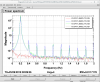
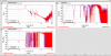
- We connected the monitor of the coil driver into the digital system and measured the amplitude spectral density (ASD) shown in the first figure when actuating MN-L with a signal at 0.2 Hz and 10,000 counts in amplitude. The harmoics are clearly visible and they are about 4 orders of magnitude smaller then the excitation at 0.2 Hz.
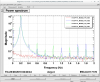
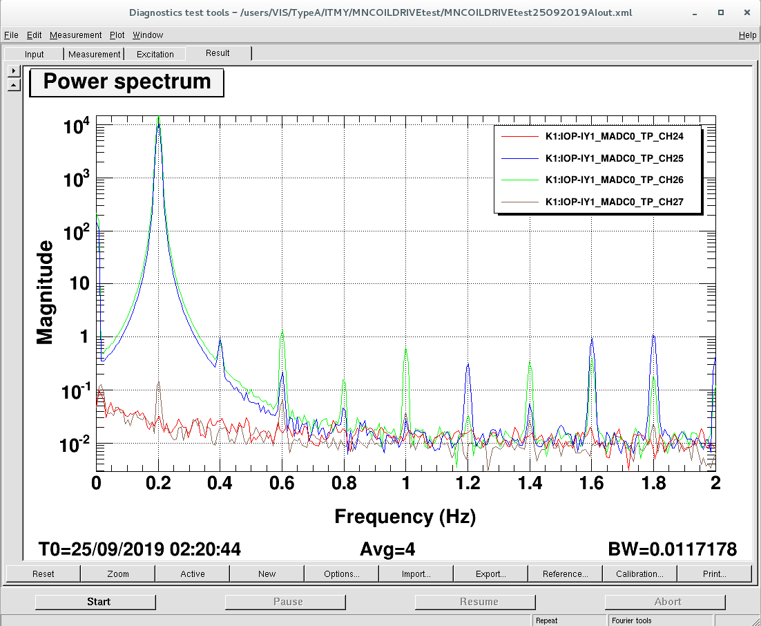
- Then we connected the output from the anti-imaging filter (before the coil driver) into the digital system and measured the ASD again. As shown in the second picture the harmonics are still there.
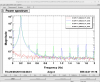
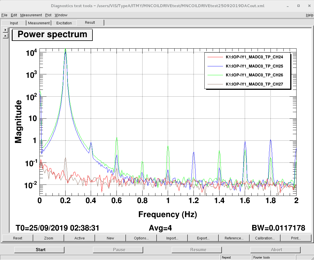
- Later we connected the output from the ADC (before the anti-imaging filter) directly into the digital system and measured the ASD again. As shown in the third picture the peaks are still there.
- We left the coil driver monitor connected in cae we want to check it again soon. See the screenshot for channel names and location of the measured data.
In a healthy systyem the amplitude of the harmonic peaks are 10,000 smaller than that of the excitation. These measurements suggest this amount of non-linearity is not the origin of the problem reported in entry 10673, which affects the End Y marionette.
Later we went to the End Y. Over there
- We connected the coil driver monitor to the digital system. (Nakano-kun changed the channels used for monitoring to DAQ channels.)
- We injected a signal in MN-L at 0.2 Hz with amplitude of 10,000 counts. We didn't see the troublesome non-linearity (so-called kick in entry 10673).
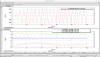
- We changed the coil driver with a normal high power coil driver and adjusted the output gain in software accordingly with a factor of 2. (Only in H1 and H2 coil channel.)
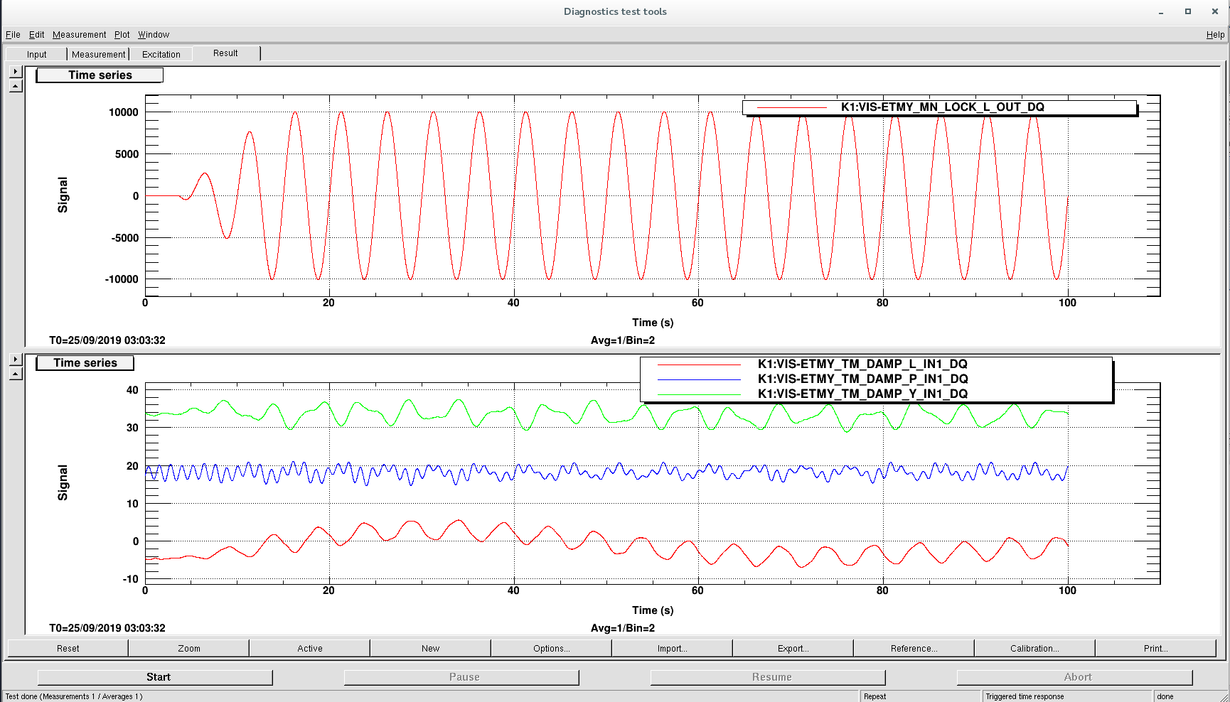
- We looked for the non-linearity again but we didn't find it. See the time series in the last picture.