Lucia, Luca
Today we investigated the noise at 238Hz visible when the coil drivers are used for the feedback control of the the vertical filters. Indeed at closed-loop this line appears in LDT-F1, LVDT-F2, LVDT-F3. We applied a lowpass at 1Hz to the digital filter of the output coil of F1, but it doesn't have any effect. We also note that its value is close to be a multiple of the powerline frequency 60Hz, so we guess that it can be due to a mass loop entering through the hardware. We suggest to check the coil driver boards when it will be possible.
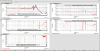
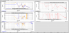
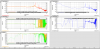
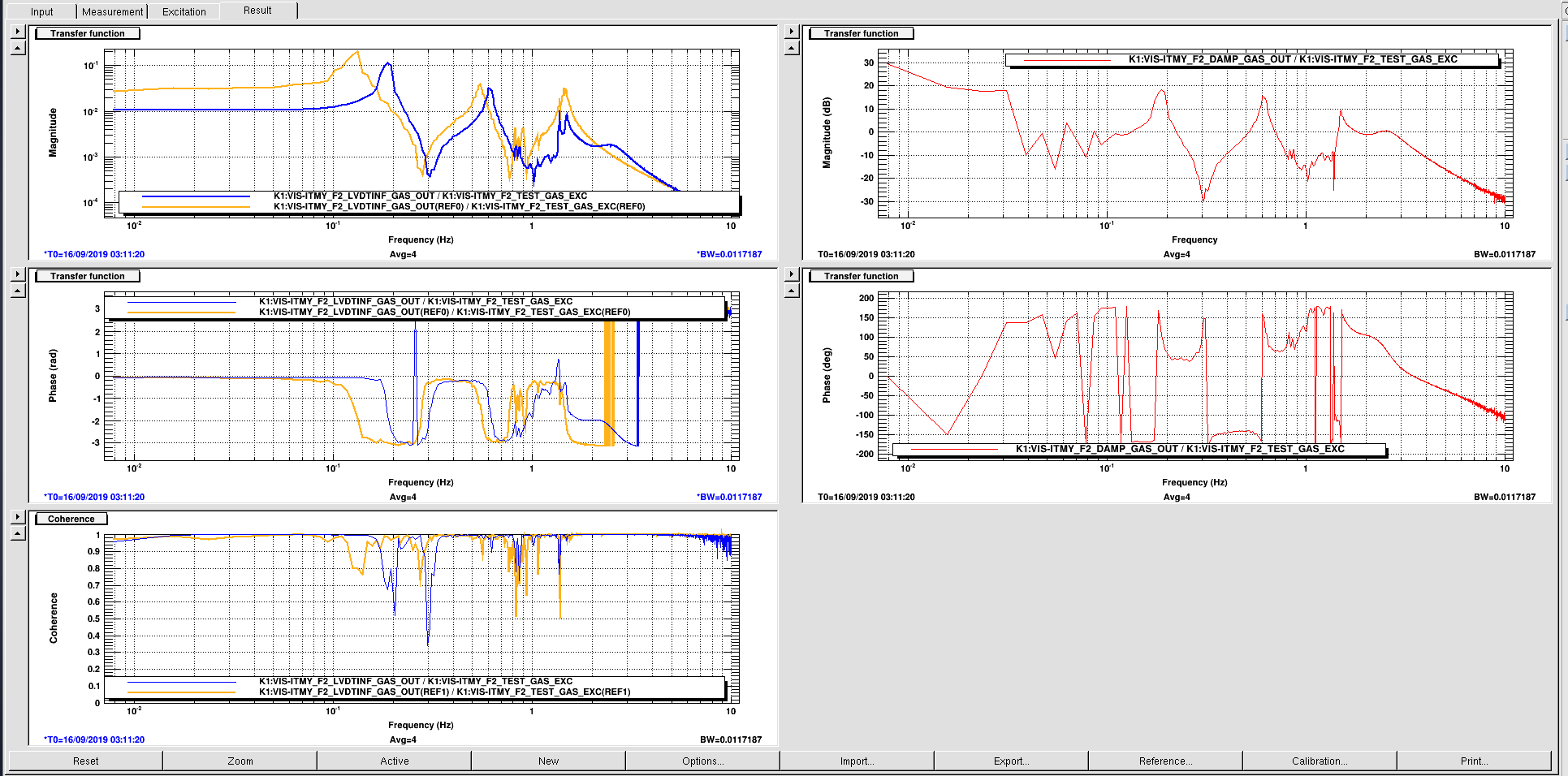
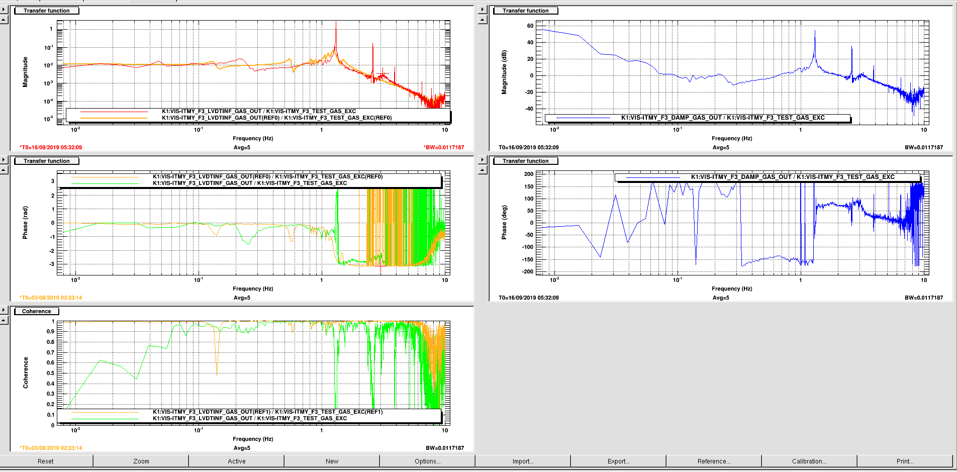
Then we measured the open loop transfer functon at each vertical filter (see attached plots):
- We observe that the phase is shifted of about 180° with respect to the measurement made in August. If we want to increase the gain of the F1 loop we should have to change the shape of the control but it would be not so easy due to the 238Hz noise line.
- we found that in F2 the gain was too low, and for this we were not able to damp the 0.2Hz peak. First we set the agin to 18dB, as shown in the attached picture. Then we increased the gain to about 26dB, keeping the loop stable without injecting too much noise. We note that also here the 238Hz noise line appears, but with a reduced amplitude (about a factor 10).
- we tried to increase also the gain for the F3 control loop, setting it to about 56dB. The filter is stable but it is not possible to increase more the gain.
- when we close the control loop of the BF it saturates due to the 238Hz noise line, then it is still open.
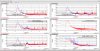
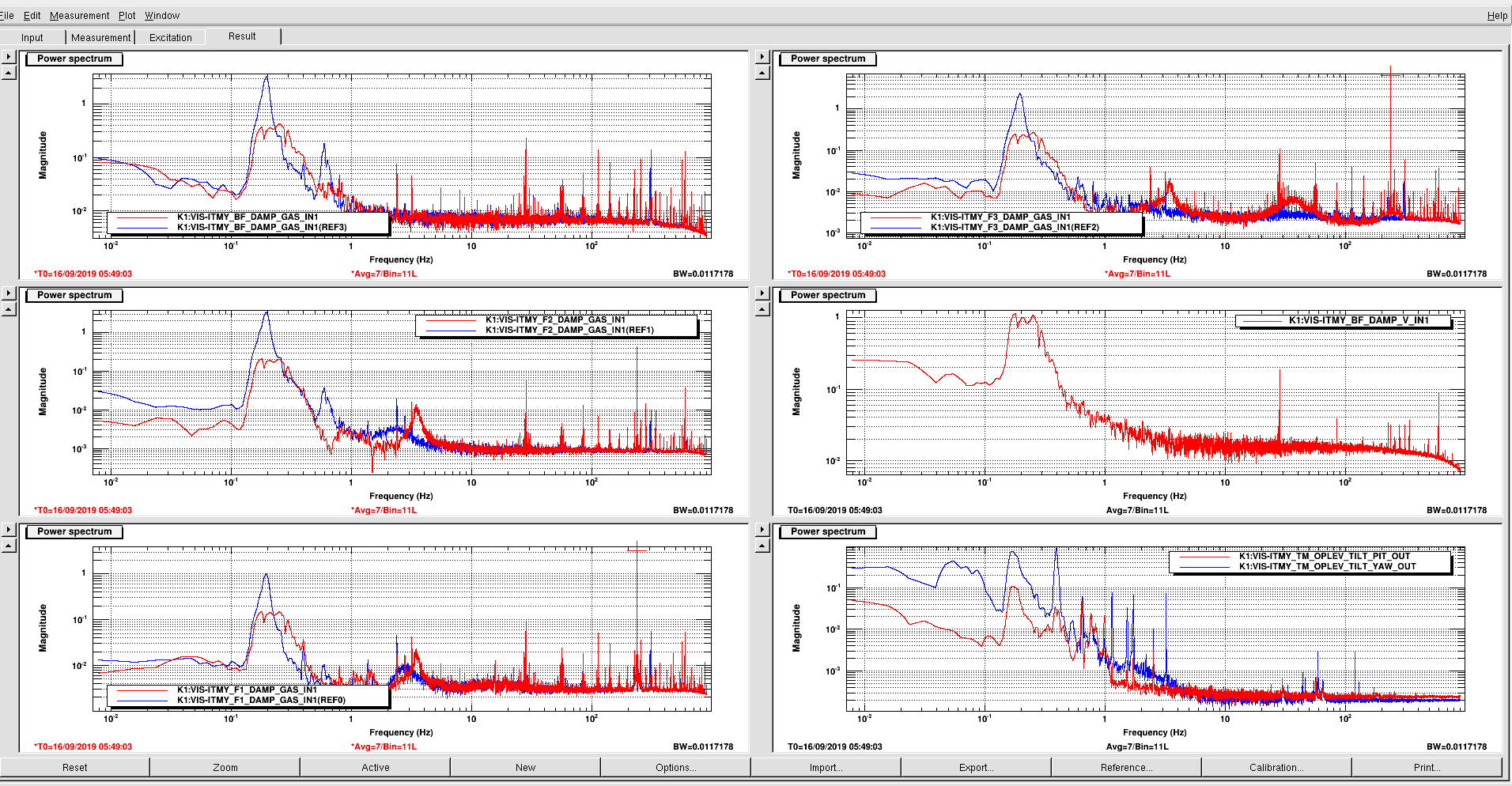
The attached spectra before (blue line) and after (red line) the tuning of the GAS filters are attached here. The 0.2Hz peak is damped.