Rana, Jenne
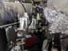
Saturday, during the AS WFS investigation and REFL beam clipping investigation, we constructed a wind shield enclosure for PRM. It has reducethe 1 Hz noise for the PRM optical lever by a factor of ~8.
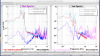
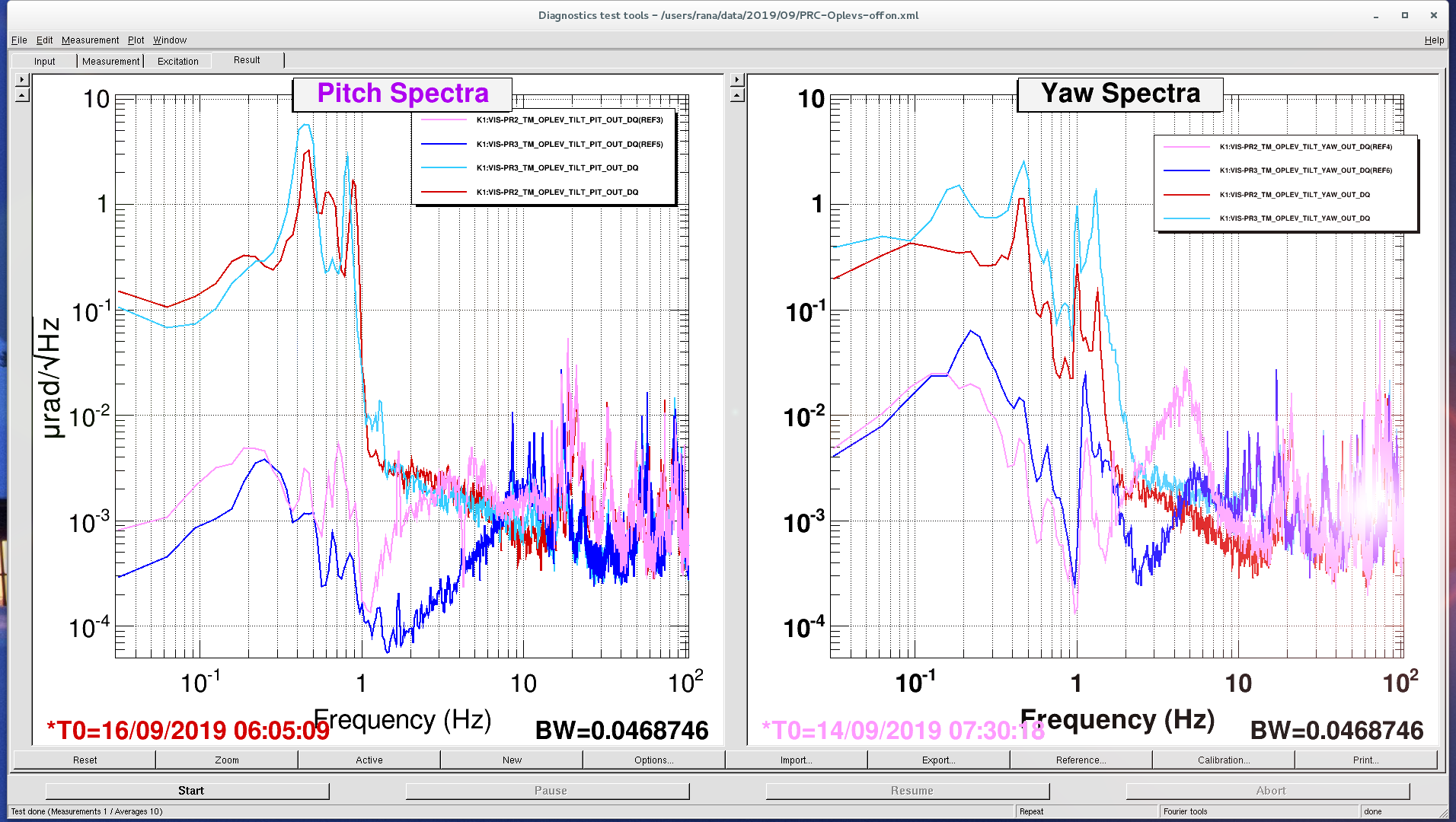
In the attached PDF, you can see the spectra of the pit/yaw spectra. Nakano-san tells me that they are all calibrated into micro-radians, so I have labeled them as such.
For PR2 and PR3, the loops are closed and so the noise below 10 Hz is suppressed. However, it seems like to me that the loops are mostly sensor noise limited (increasing the gain will not reduce the RMS motion of the mirror).
For PRM, the BLACK trace shows the open loop spectra before shield and the Blue-Gray trace shows after wind shield. For this, we're using the QPD labeled as TILT. Later, we will mix in the QPD of the other Gouy phase to cancel the large longitudinal-to-yaw coupling (otherwise, these cannot be used for feedback stabilization).
By the fact that the noise reduction was so much means that most of the wind-susceptibility comes from the laser side (not surprising). The QPD side is difficult to work on.
also, I forgot to reconnect the PRM OL beam position sensor cables , so that will have to be done next time we enter the mine.
QPD Comments:
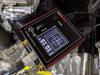
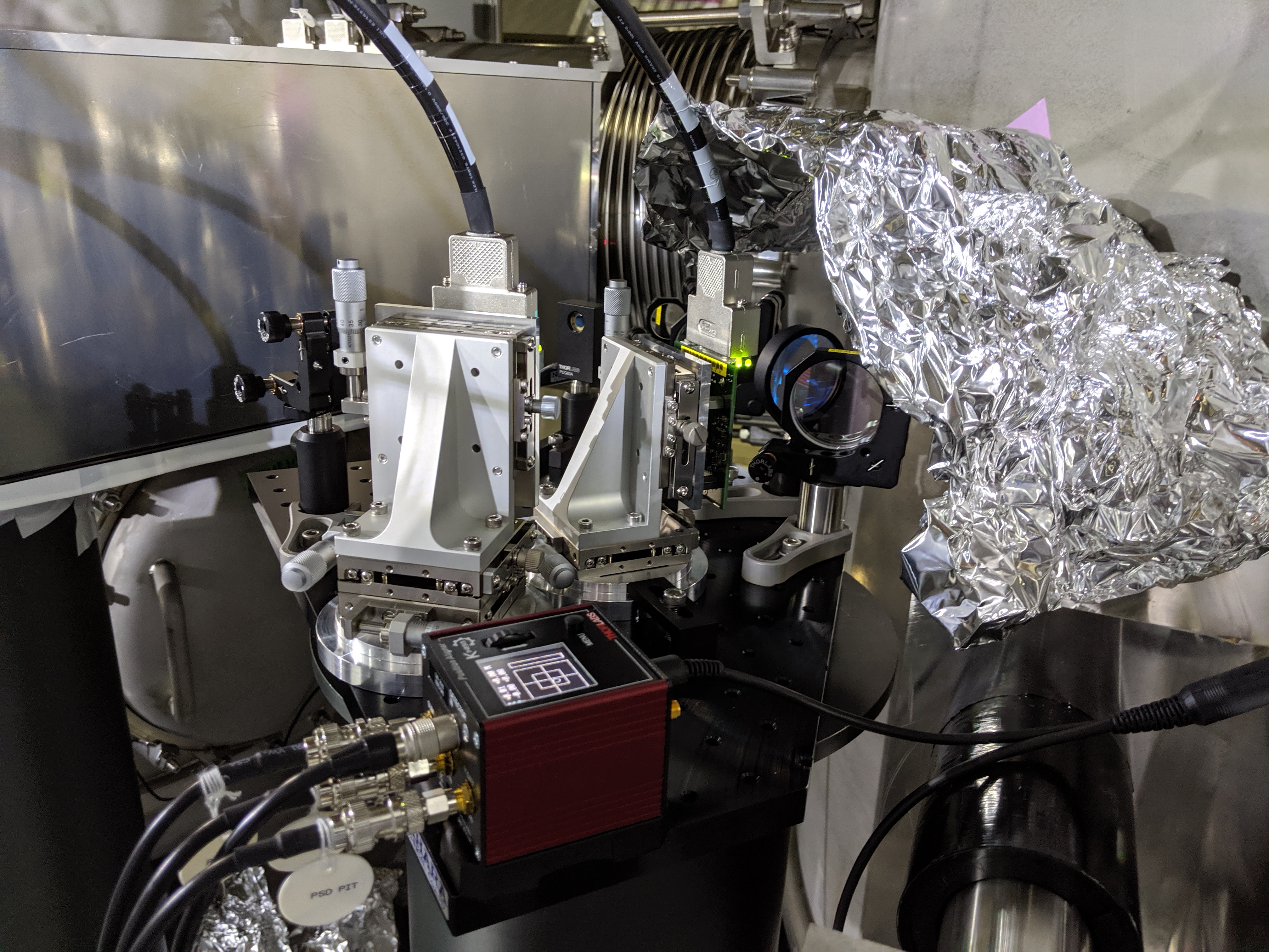
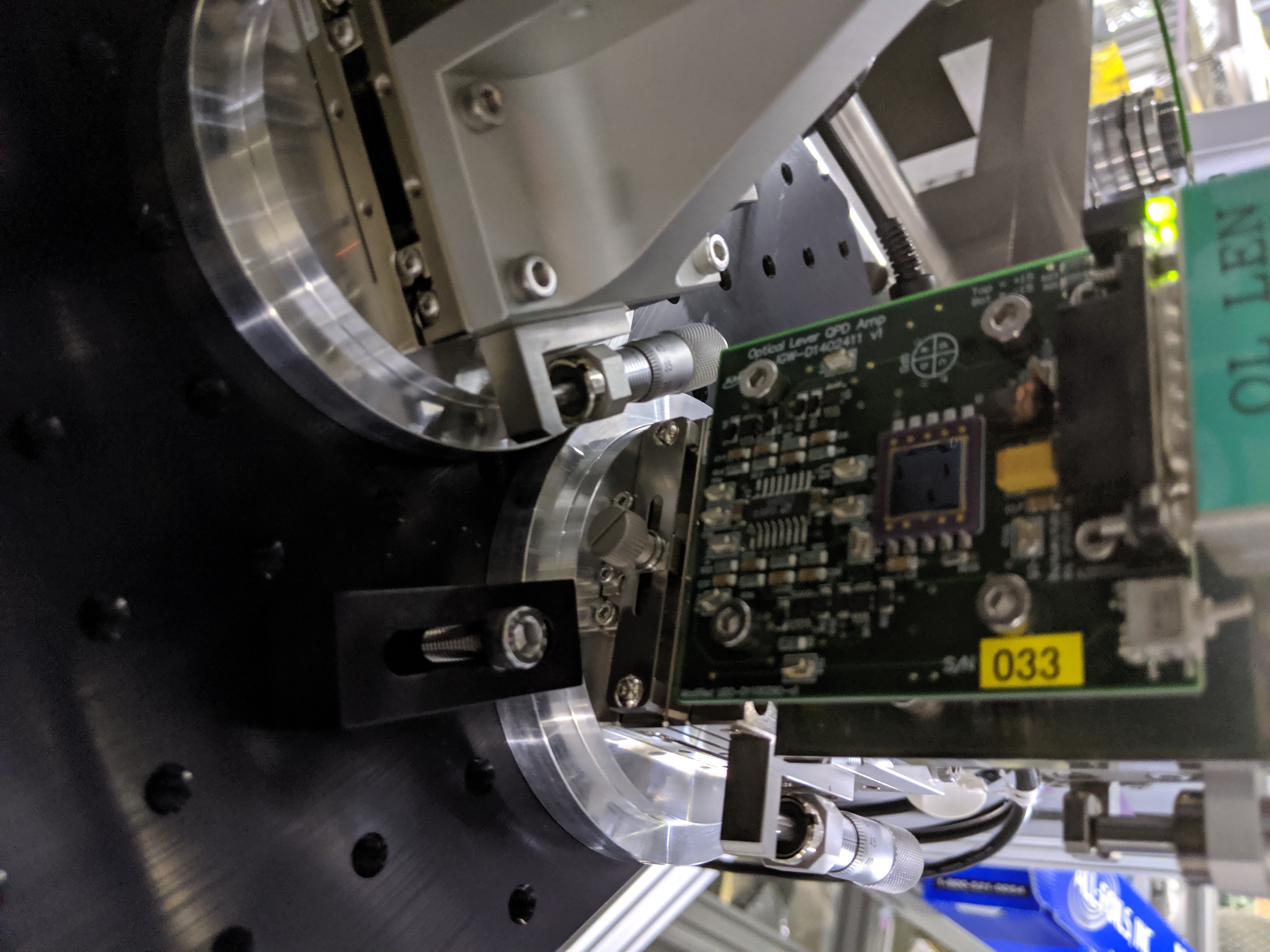
- The QPDs should be mounted in a box, not on translation stages. We want to have EMI shielding for sensitive low frequency circuits. Some opamps have a large RFI downconversion problem.
- I recommend not to use ANY translation stages on these QPDs. They are not long term stable. Instead we should use the stable mounts (e.g. Thorlabs Polaris) for steering onto the QPDs.
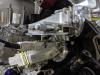
- The optics should be moved away from the edge of the breadboard so that a proper box can be attached the breadboard.
- The box used for the MMT trans is too thick. For the OL, we can just use aluminum framing (as is used on the PRM OL laser side) and some steel sheet metal. Soft rubber gaskets should be used to attach the sheet metal to the frames. The sheet metal should have a few small holes for the cables to come out and the holes should include rubber grommets so that the cable holes don't leak so much air.
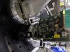
- All cables from the Optical lever laser and QPD should be strain relieved by attaching them strongly to the optical lever pier so that the vibration from the cable is minimized.
- The current 'round steel pier' approach is probably not very mechanically stable, since the pier's foot is so small relative to the moment of inertia of the pier. Ideally, the whole system should have a 'flagpole' mode resonance above 30 Hz.